NCR K430 magnetic valve - Fixed! - second row from bottom was dead

User avatar
XMIT
[ XMIT ]

15 Jul 2015, 04:17

I'm trying to get "9e7b" working.

Fixed!
Spoiler:
Turns out there was a gap in the PCB trace preventing signal from jumping the layers. Works now!
http://coronthica.com/by-uuid/9e7b7d74- ... f40501f98/

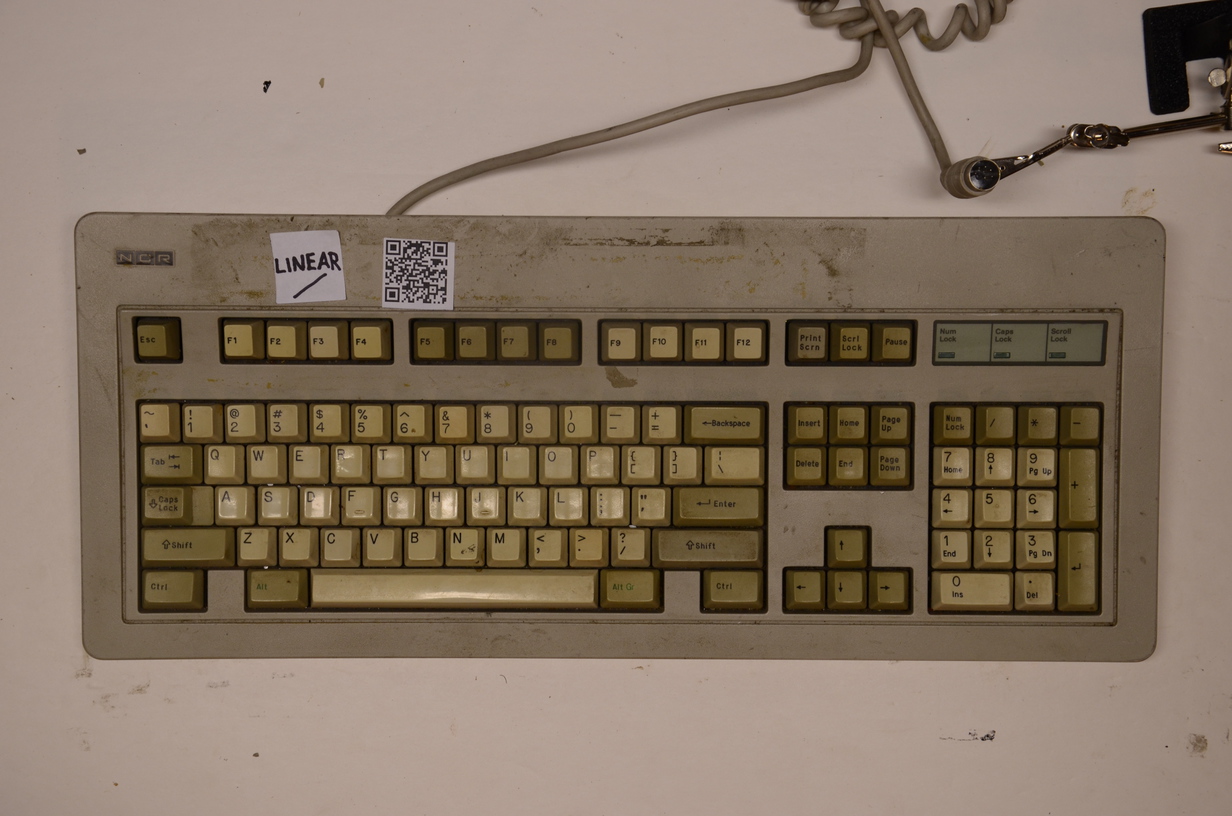
It's a full ANSI layout, looks exactly like a Cherry board, uses MX mount key switches, and is apparently magnetic valve. :o

Sadly the second row from the bottom just does not work.

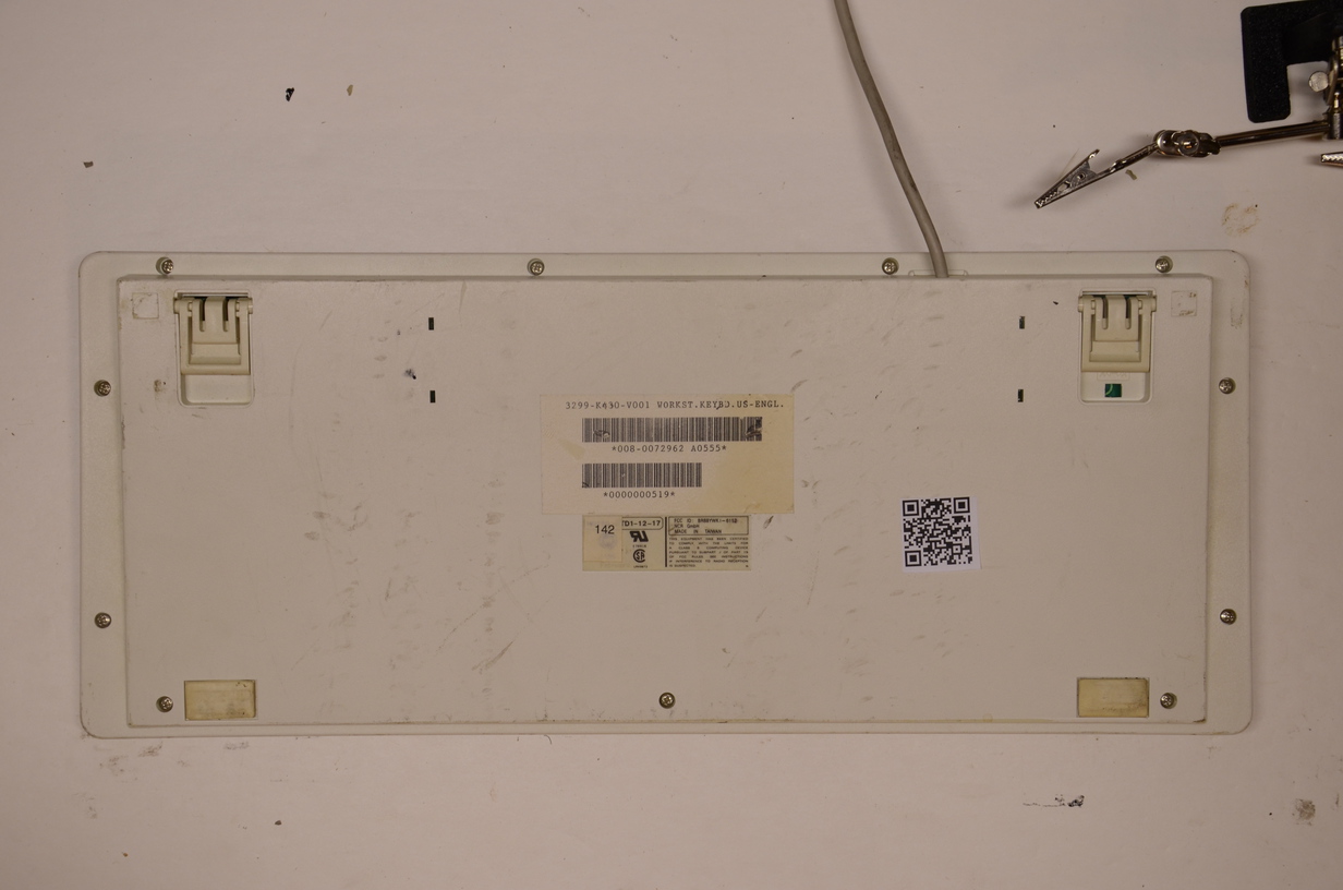
NCR GmbH
WORKST.KEYBC.US-ENGL. 3299-K430-V00
FCC ID BR88YWKI-6152

Image
Image

I'll work on posting some photos to see if anyone has any ideas. I've tried cleaning the PCB, switching around some ferrite beads, etc. I can get the keyboard to send codes from the second row by attaching a piece of wire to a particular pin (making an antenna effectively) but can't get it to work otherwise.
Last edited by XMIT on 17 Jul 2015, 05:16, edited 3 times in total.

User avatar
photekq
Cherry Picker

15 Jul 2015, 04:20

XMIT wrote: looks exactly like a Cherry board
Which one? I'm not seeing it :lol:

User avatar
XMIT
[ XMIT ]

15 Jul 2015, 04:30

Well, kind of like a Cherry board. That's unimportant.

"ZXC" row is dead.
DSC_1745.jpeg
DSC_1745.jpeg (491.47 KiB) Viewed 9155 times
Key switches are off.
DSC_1748.jpeg
DSC_1748.jpeg (423.86 KiB) Viewed 9155 times
Top side of PCB.
DSC_1755.jpeg
DSC_1755.jpeg (619.61 KiB) Viewed 9155 times
Bottom side of PCB.
DSC_1756.jpeg
DSC_1756.jpeg (531.83 KiB) Viewed 9155 times
Slider detail. The slider contains a ferrite bead that inductively couples a row (top side of PCB) and a column (bottom side of PCB).
DSC_1757.jpg
DSC_1757.jpg (308.88 KiB) Viewed 9155 times
Toroidal ferrite core 20:1 transformer (on board) detail. I swapped the bottom and next to bottom row toroidal ferrite cores and saw no change, so, the error is somewhere else.
DSC_1754.jpeg
DSC_1754.jpeg (271.91 KiB) Viewed 9155 times
Last edited by XMIT on 17 Jul 2015, 13:20, edited 1 time in total.

User avatar
Chyros

15 Jul 2015, 10:19

Woooo, pretty pictures! :) Maybe I'll get lucky at the recycling centre one day with something like this.

I agree that it doesn't look like a Cherry board :p . It looks more like a flattened-out Model M IMO.

User avatar
XMIT
[ XMIT ]

15 Jul 2015, 12:15

There will be more photos as I try to get the thing actually working again. At this point I need two tools that I don't have. The first is a schematic (I'll have to reverse engineer the board). The second is an oscilloscope (I'm looking for a nice USB connected one). Since this board does some analog sensing, amplified and passed through a Schmitt trigger, the logic analyzer won't cut it. Maybe I can get away with the ADC on the ATMEGA32U4 - I'll give Soarer's Scope a look.
Last edited by XMIT on 17 Jul 2015, 05:17, edited 1 time in total.

User avatar
XMIT
[ XMIT ]

17 Jul 2015, 04:12

FIXED!!!

Turns out there was a gap in the PCB trace on the second row from the bottom. This gap meant that current could not travel all the way around this trace. Each row has a trace that needs to be a complete loop in order to work properly and to transfer current from a column trace via a ferrite bead. With the patch to jump the dead spot in the trace the row circuit is complete and keys on this row are correctly sensed. The whole board works now!
DSC_1811.jpeg
DSC_1811.jpeg (470.38 KiB) Viewed 9067 times
DSC_1810.jpeg
DSC_1810.jpeg (404.34 KiB) Viewed 9067 times
Linear, NKRO, magnetic valve - and even with a potentiometer to set the actuation point. ANSI layout, Cherry MX mount. This is one of the most interesting, most usable keyboards I've encountered.
Last edited by XMIT on 17 Jul 2015, 13:22, edited 1 time in total.

User avatar
elecplus

17 Jul 2015, 06:13

Excellent job! The BR8 from the FCC ID belongs to ADI Corp out of Taipei, Taiwan.

User avatar
Chyros

17 Jul 2015, 10:14

Cool, awesome stuff :) .

I don't understand the workings though. Does the slider contain the ferrite ring? How can it move if it is soldered to the board? And if by induction it triggers a row and a column, how can it have NKRO?

I'm also interested in the potentiometer - is this an on-board feature to set the actuation point, then? How does that work? Never seen a keyboard in which you can set the actuation point =o .

Quite interesting board, this :) .

User avatar
XMIT
[ XMIT ]

17 Jul 2015, 13:18

Yes, this board has both ADI and OAK markings. The inside of the lower case has a decal that reports manufacturing by ADI in Taiwan. I’ll post photos at a later date.

In my earlier haste to post something - anything - about this keyboard while attempting to repair it I’m afraid that I abused some terminology which can be confusing. Here is my attempt to clarify:

- every key slider, at the bottom, has a ferrite bead. The bead, when depressed, moves into position through the PCB itself, inductively coupling traces on the bottom side (columns) and top side (rows) of the PCB.

- every row trace, located in a column between the navigation cluster and the numeric keypad, has a toroidal soft ferrite core. This toroid is used not as a coupler, but as an amplifying transformer.Specifically, this little transformer has 2 turns for the primary, and 20 turns for the secondary. It increases AC voltage by a factor of 10.

So, how does this all work?

Each row and each column has a trace on the PCB. These traces are loops. If you look at the PCB you can see that the traces themselves are shaped as if someone laid out some beads on a string and traced the outline with a pencil. Each trace both *is* a loop (forms a continuous circuit, though perhaps with one opening for connecting a power source) and *has* several loops (has several places where the traces diverge from one another, often around a hole through the PCB).

Recall that current going around a loop will induce a magnetic field through the loop and vice versa.

So, if you were to apply a pulse of current to the trace configuration I just described above, you would see a magnetic pulse (albeit a tiny one) at every position where the traces diverge.

The keyboard controller sends pulses down the columns, and listens for pulses coming back on the rows. Strictly speaking the traces for circuits on the columns are open (since they can be connected to power and ground), and the traces for the rows are closed (since the ends are connected together through a transformer creating a closed loop).

When a key is pressed:
- the keyboard controller sends an electrical pulse down a column. This is achieved by connecting the ends of the column traces on the back side of the PCB to power and ground for a short period of time;

- the user’s finger moves a ferrite bead into position between the top and bottom layers, between the column and row traces, inductively coupling them;

- the pulse from the column induces a magnetic field in the ferrite bead;

- the ferrite bead’s magnetic field induces a spike in current in the row trace;

- the spike in current is amplified by a factor of 10x and sent off to a Schmitt trigger (a digital inverter with hysteresis) for logic level conversion and interfacing with the rest of the board.

Very clever.

With my board having one row broken - and still able to sense keys on that row if I did some other tricks like grounding the output of the Schmitt trigger that was connected to the output of that row - I eventually knew that the issue must be an electrical issue with that particular row. With a multimeter I eventually found a gap in the trace and fixed it with a soldered in jumper wire. I didn’t have to break out the heavy tools like the oscilloscope and reverse engineering the entire PCB schematic. I knew it had to be something simple and it was.

Now, Chyros had two good questions:

1. Sensitivity. There is a potentiometer (variable resistor) in the upper right hand corner of the board. Empirically this sets the key sensitivity, or, the amount of travel required before a key press event is registered. My hypothesis is that this potentiometer sets the amplitude of the pulse going down the columns. More current means easier sensing and less travel, less current means more difficult sensing and more travel. I have not proven this with an oscilloscope.

2. N-key rollover. Empirically, with Soarer’s converter, I have observed NKRO with this board. I can mash as many keys as possible at once and they will register. If I ground the output of a single row’s Schmitt trigger I can see all of the keys on that row detected and released. How does this work, if the switches couple rows and columns together? My guess is that the coupling is not perfect; rather, it is somewhat lossy, and has been carefully tuned to prevent ghosting. The signal on the rows after sensing is quite weak and needs to be amplified by a factor of 10 to activate the Schmitt trigger at all (with some tolerance; the potentiometer can vary this slightly). Since ghosting requires three keys to be pressed, by the time a pulse of current has made it through three ferrite beads, it may be too small to be detected. Just a hypothesis.

To model this, imagine replacing the diodes on a switch based board with resistors, and determining that a switch is “on” if the output voltage registers above say 3V on a system where Vcc is 5V. The resistors won’t work as well as the diodes and will burn power but will still provide NKRO with tuning. Clearly diodes are the better approach here.

Anyway. I’m going to whiten the keys, wipe the PCB with isopropyl alcohol, use some hot glue to tack down the heavy toroidal ferrite transformer cores (28 year old glue has given way). lubricate all of the sliders and get some photos. It may take a while but I fully expect this keyboard to be in my regular rotation now!

User avatar
derzemel

17 Jul 2015, 15:15

Image

jbondeson

17 Jul 2015, 16:14

Very interesting stuff! Now we need to dig up a few more of these boards so I can get one :evilgeek:

And I'm also starting to wonder if you actually sleep...

User avatar
Muirium
µ

17 Jul 2015, 16:33

Baby in the house. Safe to assume not!

User avatar
XMIT
[ XMIT ]

17 Jul 2015, 16:45

Maybe this one needs a video to explain it. That was a long write up. Blame Chyros, he wanted an explanation. ;-)

It's all based on Lenz's Law:
https://en.wikipedia.org/wiki/Lenz%27s_law

HaaTa did a nice writeup of the magnetic valve principle a while ago, check here:
http://deskthority.net/keyboards-f2/raf ... t6216.html

It does take some effort to understand this if the theory is new to you. But, once you understand it, you'll see that this is a beautiful, simple, elegant, extremely reliable, and relatively cheap way to build a keyboard. Think of it as a mass market Hall effect board, kind of. (This board does not use the Hall effect at all.)

That being said I have no idea how this failed in the first place. It would take a small rock or something to scratch the traces on the board. If it was outside in a pile for a decade maybe that could do it. It looked like someone had opened the keyboard before and did a sloppy job of trying to fix it and failing.

I sleep when no one is looking. ;-)
Last edited by XMIT on 17 Jul 2015, 16:47, edited 1 time in total.

jbondeson

17 Jul 2015, 16:47

Muirium wrote: Baby in the house. Safe to assume not!
See, I discounted that cause I was assuming he wasn't an android... cause most of us mortals when inflicted with the Baby Insomnia are total zombies. Not "Diagnose and fix complex electrical systems" awake.

Anyone have a Voight-Kampff machine? :ugeek:

User avatar
Chyros

17 Jul 2015, 21:06

XMIT wrote: [lots of words]
Thanks, very well explained, that makes 100% sense actually! I'm glad I did some physics in university xD . What a great system, do other magnetic valve switches, like ITW magnetic valves, work like this too, then?

As for the NKRO, is it possible the pulses are sent sequentially through the columns? That way, each signal coming from the rows would be from a timeframe that corresponds to just one specific column, assigning it unambiguously to one coordinate.

User avatar
XMIT
[ XMIT ]

17 Jul 2015, 21:16

Chyros wrote:
XMIT wrote: [lots of words]
Yeah... 971 apparently. :shock:

Code: Select all

$ wc -w description.txt 
971 description.txt
Chyros wrote: Thanks, very well explained, that makes 100% sense actually! I'm glad I did some physics in university xD . What a great system, do other magnetic valve switches, like ITW magnetic valves, work like this too, then?
Yes, kind of.

ITW/Cortron uses the same idea. On those, there are two loops of wire with a small toroidal ferrite core coupling them. The switch stem has a small permanent magnet that moves into position and prevents the small toroidal ferrite core from performing coupling. So those are default-high with sense low; these are default-low with sense high. That high pulse gets amplified and sent through a Schmitt trigger inverter. That's why one can ground the output end of the inverter to mimic testing - a trick that I used several times in fixing this board.
Chyros wrote: As for the NKRO, is it possible the pulses are sent sequentially through the columns? That way, each signal coming from the rows would be from a timeframe that corresponds to just one specific column, assigning it unambiguously to one coordinate.
Yes, the pulses down the columns are most certainly sequential, from left to right.

This is clear if one grounds the inverted output of one of the row sensors. You can see the keys light up in sequence, not simultaneously. Knowledge of the timing of sending pulses down the columns would indeed allow the controller to implement anti-ghosting by only checking for keys in that column.

I still think this is a really neat design.

User avatar
XMIT
[ XMIT ]

19 Jul 2015, 05:52

Alright, it is finally all back together. It took quite a while to lubricate all of the sliders with Finish Line Extreme Fluoro (rumored to be a combination of DuPont Krytox 204 and 205). I was going to retr0bright (whiten) the keys but decided against it as I have too many other projects underway. The stems are in fact Cherry MX compatible.

These are heavy linears. The feel is extremely similar to Cherry MX Black, but even heavier. Actuation is about 65-70g at the highest sensitivity setting. Bottoming out is rather more than that. Yeesh! There is no scratchiness at all. Maybe a spring mod is in order but finding short enough springs would be a real challenge.

I will need 14 extra Filco style stabilizers if I want to put any other key cap set on here. Does anyone have any spares? This keyboard seems like a fitting home for a PBT key set.

terrycherry

29 Feb 2016, 05:01

I got a luck to take this rare keyboard too.
Good to see you have lots of detail talked about this.
Mine has the AT connector. Is it a really work on PC?

User avatar
XMIT
[ XMIT ]

16 Mar 2016, 03:58

terrycherry wrote: I got a luck to take this rare keyboard too.
Good to see you have lots of detail talked about this.
Mine has the AT connector. Is it a really work on PC?
Yes it does, with Soarer's converter! It even gets full NKRO. Enjoy!

User avatar
Redmaus
Gotta start somewhere

16 Mar 2016, 04:02

How did I miss this? :|

Cherry mount, NKRO, ANSI, pure badassery!

Enjoy the board XMIT!

User avatar
XMIT
[ XMIT ]

08 Jul 2016, 17:12

This board is still around.

Recently, I changed out the awful yellow thin ABS doubleshots for some authentic Cherry doubleshots (okay, maybe some of the Function keys are lasered, I had to make do with what I had available).
600_1708.jpg
600_1708.jpg (145.01 KiB) Viewed 8519 times
The Space bar is still yellow. I may whiten it at some point. Putting a better Space bar on there will require a plate mod. I'll get to it one of these days.

terrycherry

08 Jul 2016, 18:28

Nice clean work. Could it work on the modern PC without converter?

User avatar
XMIT
[ XMIT ]

08 Jul 2016, 18:30

terrycherry wrote: Nice clean work. Could it work on the modern PC without converter?
I don't recall if the protocol is XT or AT. I believe it is AT. It has an XT-style five pin connector (which you can see in the first post). So, yes, I believe it should work.

Again, it works great with Soarer's Converter on USB.

tigpha

09 Jul 2016, 12:30

Hi Xmit,

May I ask a question about the PCB layout? What might be the purpose of the extra columns without holes in the loops, in between the columns which have holes in the loops where the ferrite beads attached to the keys pass through? Do these serve as reference loops against which the sensor loops are compared? Or do they serve to magnetically, or inductively separate the columns that are closer to each other?

User avatar
XMIT
[ XMIT ]

09 Jul 2016, 14:30

tigpha wrote: May I ask a question about the PCB layout? What might be the purpose of the extra columns without holes in the loops, in between the columns which have holes in the loops where the ferrite beads attached to the keys pass through? Do these serve as reference loops against which the sensor loops are compared? Or do they serve to magnetically, or inductively separate the columns that are closer to each other?
This is pure speculation but I see two options:
1. The spare loops are used as a reference by the firmware.
2. The PCB is designed to have multiple designs used, and thus, offer multiple key positions.

Moreover, I'm not sure these goals are orthogonal. It's possible that with one design, one set of loops is used as sensing and the other for reference, and with another design the purposes of the loops are switched, if that makes sense.

The only way to really know for sure would be do dump, disassemble, and inspect the microcontroller code. I'm too lazy to do this, sorry.

listofoptions

24 Jan 2020, 18:55

XMIT wrote:
09 Jul 2016, 14:30
tigpha wrote: May I ask a question about the PCB layout? What might be the purpose of the extra columns without holes in the loops, in between the columns which have holes in the loops where the ferrite beads attached to the keys pass through? Do these serve as reference loops against which the sensor loops are compared? Or do they serve to magnetically, or inductively separate the columns that are closer to each other?
This is pure speculation but I see two options:
1. The spare loops are used as a reference by the firmware.
2. The PCB is designed to have multiple designs used, and thus, offer multiple key positions.

Moreover, I'm not sure these goals are orthogonal. It's possible that with one design, one set of loops is used as sensing and the other for reference, and with another design the purposes of the loops are switched, if that makes sense.

The only way to really know for sure would be do dump, disassemble, and inspect the microcontroller code. I'm too lazy to do this, sorry.
hey! just saw this and thought id drop in a comment (sorry to resurrect a very dead thread!)
those extra traces aren't any thing like controller reference pads (err well they are, but the controller doesn't use them), or multiple optional key positions; rather, they're actually something far more clever!

so what happens is (xmit has like 99% of this already):
controller strobes column ("voice coil") current flows down the column that has holes in it, around the last pad, back up to the top.

then the current flows into the middle column ("reference coil") between two voice coils.
when it flows down this reference coil its actually flowing in such a way that the magnetic field generated from the flowing current is in the opposite direction from the strobed voice coil.

due to this, when a key is not depressed the current induced in the row traces ("sense coil") from both the voice coil, and its nearby reference coil cancel out as they are flowing in opposite directions. therefore little to no voltage (flowing current in a wire causes voltage, as the wire has some resistance to flow) can be sensed from the key.

so when a key is depressed, there is more coupling of the sense coil with voice coil than there is between the sense coil and the reference coil, so the current induced by the voice coil in the sense coil can be detected, as there's more of it.

the layout of the board is such that (for the most part) every two voice coils share a sense coil (the columns near the sense transformers get iffy, they're pulling some shenanigans there, but the following still holds), saving some space. they're using 74145 to select one of ten voice coils to strobe (sometimes its less). the reference coils for the sets of voice coils that each decoder / selector controls all go to the same star point ground under the decoder/selector. this is mainly for signal purity shenanigans. the effect of this is the ability to have NKRO without timing shenanigans, or much any thing else really!

as for the purpose of the variable resistor; its to control the current supply for the sense coil transformers. the 74145 is an inverted output selector, meaning that the selector changes the output of the pin to low to select a voice coil column, not to high.

hopefully that makes sense!

TL;DR : differential detection of changes in inductive coupling.
aihk

11 Apr 2022, 13:56

I also have this keyboard, but I don't know how to make it work, could you tell me how do you make it work, I found the orange line out of NPN transistors to the terminal, don't know the role of the thread.

User avatar
XMIT
[ XMIT ]

13 Apr 2022, 15:48

aihk, I don't have this keyboard handy at the moment. The more photos you are able to post, and the more description of the behavior you are seeing that you are able to offer, the better I and others will be able to help you.

Post Reply

Return to “Keyboards”