So,
I have here a trackpoint module from an old thinkpad keyboard, that has also 3 mouse buttons, I was considering integrating those in a custom keyboard that operates over a teensy 2, I was wondering if there is some sort of knowledge I can gather about connecting those 2 thinkpad mouse inputs (buttons+clit) to the teensy that already handles the switches.
I also have the rubber dome sheets and maybe they can result handy for the actuation of the mouse clicks (maybe is that possible to connect some wires to the trace of those plastic sheets?
Maybe I can post some pictures but this trackpoint module has a big V9E printed on the back, and PSB8M8 and has 8 soldering traces on the back.
Connecting thinkpad trackpoint mouse+buttons to teensy 2
-
mtl
- Location: USA
- Main keyboard: Custom
- Main mouse: IBM TrackPoint IV
- Favorite switch: Cherry MX Clicky
- DT Pro Member: -
See the SSII Controller Board section of this page: http://deskthority.net/wiki/MX13_SpaceS ... ckPoint_IV
If your source keyboard was the same, that can help you. If not, then yes, just follow the traces from your rubber dome sheets. Many IBM TrackPoint modules output PS/2. There are a few teensy firmware implementations that will control the TP module and report it as a USB mouse to the host. TMK is a good one.
Edit: This one has 8 pins and may be more like yours: https://geekhack.org/index.php?topic=89 ... #msg775152
-
araif
- DT Pro Member: -
I saw that last thread mtl posted, I think it is somewhat different from mine because I managed to trace some pins from the keyboard, for example I have button 1 on pin 4, button 2 on pin 3 and button 3 on pin 5, the controller on the trackpoint is a PTPM754DR and I can't find spech of this one, also I've tried to ask directly to the person that posted that picture in the last thread but I've got no response. Is there a way to discover by tracing without connecting back the keyboard, what pins are for clock, data , rst etc? later I'll post some pictures of the trackpoint.
-
araif
- DT Pro Member: -
here it is some images of the trackpoint and what I could trace https://imgur.com/a/Dj1bG
-
araif
- DT Pro Member: -
I'm asking here https://electronics.stackexchange.com/q ... 202_155671 and this sorts out some material on the geekhack forum, probably that will end up in a solution.
-
araif
- DT Pro Member: -
I would like to do a recap and add some info about the configuration of the tmk firmware for handling both the keyboard matrix and the trackpoint with a single teensy 2.0 (I have a 60% kb with 15x5 colxrows, so I have enough pins on the controller).
Wiring
For the wiring you should see those resources, expecially the first one, as it shows various trackpoints versions and the RC filter you have to wire for the use with tmk firmware.
https://geekhack.org/index.php?topic=55 ... msg1291412
http://sprintek.com/documents/datasheet ... asheet.pdf
https://www.mikrocontroller.net/attachm ... tpm754.pdf
Flashing the firmware
First of all you should not use the polling configuration but the interrupt or usart version, that because I saw a lot of ghosting like problems in the polling version, where keys where not detected if not pressed repeatedly or hold.
You should refer to the tmk onekey example for the configuration, see the config.h and Makefile
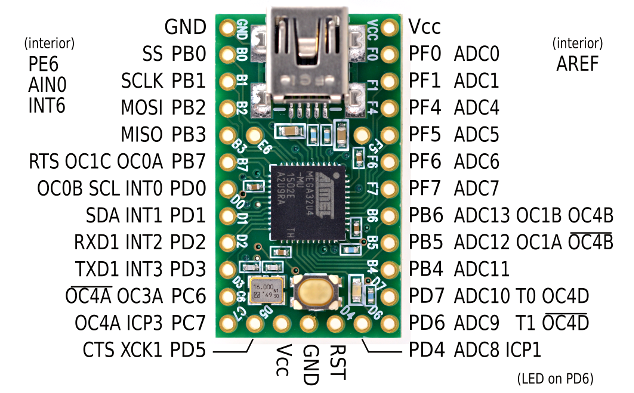
I will refer to the teensy 2 pinout http://www.pjrc.com/teensy/pinout2a.png
1) for the interrupt version you have to use any INTn or PCINTn pin for clock, and any pin for data, this should reflect the config and initialization of the interrupt array on your config, for example say that you are using INT2 pin and pd5 for data, the config you have to change is like this: (this is not really tested as I'm not really sure of the initialization code)
2) For the usart version you must use the PD5 (XCK) pin for the clock and PD2 (RXD1) for data, I'm using this config mode as presumably it should wake up less frequently the int handler.
3) the makefile should include
With this on place you should be free to go.
Wiring
For the wiring you should see those resources, expecially the first one, as it shows various trackpoints versions and the RC filter you have to wire for the use with tmk firmware.
https://geekhack.org/index.php?topic=55 ... msg1291412
http://sprintek.com/documents/datasheet ... asheet.pdf
https://www.mikrocontroller.net/attachm ... tpm754.pdf
Flashing the firmware
First of all you should not use the polling configuration but the interrupt or usart version, that because I saw a lot of ghosting like problems in the polling version, where keys where not detected if not pressed repeatedly or hold.
You should refer to the tmk onekey example for the configuration, see the config.h and Makefile
I will refer to the teensy 2 pinout http://www.pjrc.com/teensy/pinout2a.png
1) for the interrupt version you have to use any INTn or PCINTn pin for clock, and any pin for data, this should reflect the config and initialization of the interrupt array on your config, for example say that you are using INT2 pin and pd5 for data, the config you have to change is like this: (this is not really tested as I'm not really sure of the initialization code)
Code: Select all
/* PS/2 mouse interrupt version */
#ifdef PS2_USE_INT
/* uses INT2 for clock line(ATMega32U4) */
#define PS2_CLOCK_PORT  PORTD
#define PS2_CLOCK_PIN   PIND
#define PS2_CLOCK_DDR   DDRD
#define PS2_CLOCK_BIT   2
#define PS2_DATA_PORT   PORTD
#define PS2_DATA_PIN    PIND
#define PS2_DATA_DDR    DDRD
#define PS2_DATA_BIT    5

#define PS2_INT_INIT()  do {    \
    EICRA |= ((1<<ISC21) |      \
              (0<<ISC20));      \
} while (0)
#define PS2_INT_ON()  do {      \
    EIMSK |= (1<<INT2);         \
} while (0)
#define PS2_INT_OFF() do {      \
    EIMSK &= ~(1<<INT2);        \
} while (0)
#define PS2_INT_VECT   INT2_vect
#endif
Code: Select all
/* PS/2 mouse USART version */
#ifdef PS2_USE_USART
#if defined(__AVR_ATmega16U4__) || defined(__AVR_ATmega32U4__)
/* XCK for clock line and RXD for data line */
#define PS2_CLOCK_PORT  PORTD
#define PS2_CLOCK_PIN   PIND
#define PS2_CLOCK_DDR   DDRD
#define PS2_CLOCK_BIT   5
#define PS2_DATA_PORT   PORTD
#define PS2_DATA_PIN    PIND
#define PS2_DATA_DDR    DDRD
#define PS2_DATA_BIT    2

/* synchronous, odd parity, 1-bit stop, 8-bit data, sample at falling edge */
/* set DDR of CLOCK as input to be slave */
#define PS2_USART_INIT() do {   \
    PS2_CLOCK_DDR &= ~(1<<PS2_CLOCK_BIT);   \
    PS2_DATA_DDR &= ~(1<<PS2_DATA_BIT);     \
    UCSR1C = ((1 << UMSEL10) |  \
              (3 << UPM10)   |  \
              (0 << USBS1)   |  \
              (3 << UCSZ10)  |  \
              (0 << UCPOL1));   \
    UCSR1A = 0;                 \
    UBRR1H = 0;                 \
    UBRR1L = 0;                 \
} while (0)
#define PS2_USART_RX_INT_ON() do {  \
    UCSR1B = ((1 << RXCIE1) |       \
              (1 << RXEN1));        \
} while (0)
#define PS2_USART_RX_POLL_ON() do { \
    UCSR1B = (1 << RXEN1);          \
} while (0)
#define PS2_USART_OFF() do {    \
    UCSR1C = 0;                 \
    UCSR1B &= ~((1 << RXEN1) |  \
                (1 << TXEN1));  \
} while (0)
#define PS2_USART_RX_READY      (UCSR1A & (1<<RXC1))
#define PS2_USART_RX_DATA       UDR1
#define PS2_USART_ERROR         (UCSR1A & ((1<<FE1) | (1<<DOR1) | (1<<UPE1)))
#define PS2_USART_RX_VECT       USART1_RX_vect
#endif
#endif

#endif
3) the makefile should include
Code: Select all
PS2_MOUSE_ENABLE = yes  # PS/2 mouse(TrackPoint) support
#PS2_USE_BUSYWAIT = yes # uses primitive reference code
#PS2_USE_INT = yes      # uses external interrupt for falling edge of PS/2 clock pin
PS2_USE_USART = yes     # uses hardware USART engine for PS/2 signal receive(recomened)
PS2_MOUSE_DEBUG = no
With this on place you should be free to go.
-
tentator

- Location: ZH, CH
- Main keyboard: MX blue tentboard
- Main mouse: Pointing Stick
- Favorite switch: Cherry MX Blue and Model F BS
- DT Pro Member: -
Hi.. maybe a bit necro but..
I'm reversing the pinout of my trackpoints (I have two and both seem to be different to all the rest I find so far on the net).. I easily found out the VCC and the GND (and the three mouse buttons) but have some doubt about understanding which of the thre is the DATA, CLOCK and RESET:
(I read the above with my meter)
My guess would be:
pinZ is reset because the only with 0V
pinY is clock because the only with 0Hz measured??
What do you think?
And for the above post: in the section 1) is there a reason why it is slightly different to what I see on the omnikey?
also in section 3) I think there is an endif too much in the end (I mean if you have to copy paste it in an existing config.h that doesn't have it..)
I'm reversing the pinout of my trackpoints (I have two and both seem to be different to all the rest I find so far on the net).. I easily found out the VCC and the GND (and the three mouse buttons) but have some doubt about understanding which of the thre is the DATA, CLOCK and RESET:
Code: Select all
pinX pinY pinZ
5V   5V   0V
2khz 0khz 1khz
My guess would be:
pinZ is reset because the only with 0V
pinY is clock because the only with 0Hz measured??
What do you think?
And for the above post: in the section 1) is there a reason why it is slightly different to what I see on the omnikey?
Code: Select all
	#define PS2_INT_INIT()  do {    \
		EICRA |= ((1<<ISC11) |      \
				  (0<<ISC10));      \
	} while (0)
	#define PS2_INT_ON()  do {      \
		EIMSK |= (1<<INT1);         \
	} while (0)
	#define PS2_INT_OFF() do {      \
		EIMSK &= ~(1<<INT1);        \
	} while (0)
	#define PS2_INT_VECT   INT1_vect
	#endif
-
tentator
- Location: ZH, CH
- Main keyboard: MX blue tentboard
- Main mouse: Pointing Stick
- Favorite switch: Cherry MX Blue and Model F BS
- DT Pro Member: -
FYI: workshop-f7/t400-keyboard-trackpoint-pinout-t7678.html
ok the pinouts are found and confirmed.. still unclear why my firmware with PS2_USE_USART did not work while another one that uses PS2_INT is ok... will try on to see further..
tent:wq
ok the pinouts are found and confirmed.. still unclear why my firmware with PS2_USE_USART did not work while another one that uses PS2_INT is ok... will try on to see further..
tent:wq
-
tentator
- Location: ZH, CH
- Main keyboard: MX blue tentboard
- Main mouse: Pointing Stick
- Favorite switch: Cherry MX Blue and Model F BS
- DT Pro Member: -
also watch out in the above ps2 interrupt version in section 2) the int is hardcoded to 2 and limited to int pins so to avoid confusions I'd remove the
part since it's wrong and creates confusion..
also in the makefile section 3) do not forget to add in the end of the Makefile (or check the presence) of an include of:
now everything works fine.. both firmware and the reversed pins of the trackpoints I have.. puhh... 
tent:wq
Code: Select all
#define PS2_CLOCK_PORT  PORTD
#define PS2_CLOCK_PIN   PIND
#define PS2_CLOCK_DDR   DDRD
#define PS2_CLOCK_BIT   2
#define PS2_DATA_PORT   PORTD
#define PS2_DATA_PIN    PIND
#define PS2_DATA_DDR    DDRD
#define PS2_DATA_BIT 5also in the makefile section 3) do not forget to add in the end of the Makefile (or check the presence) of an include of:
Code: Select all
##### Enable PS/2 TrackPoint !!!
include $(TMK_DIR)/protocol.mk
##### Enable PS/2 TrackPoint ENDtent:wq