Page 1 of 1
Copper contractor came off pcb, need some tips.
Posted: 18 Sep 2015, 15:48
by burn1nsun
I disovered that my caps lock is messed up:
Top:
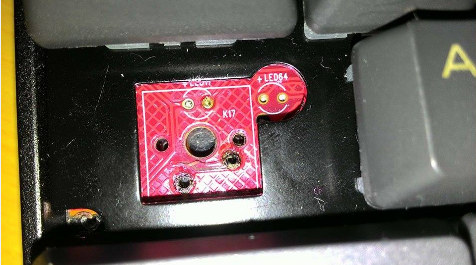
Back(It looks a lot worse than it is I think, the black and brown stuff should be like a soldering paste type of thing):
Could someone make something in paint demonstrating what should I connect to where? (I know I sound like a dumbass, but I really want very specific info for this

)
Thanks in advance!
Posted: 18 Sep 2015, 15:51
by Engicoder
Wow! Any idea how that happened?
Posted: 18 Sep 2015, 15:55
by chzel
God...
Let's see...
1) Get some larger pics so we can see better detail.
2) Is it a stock Poker 2 or what?
3) Stop using a blowtorch to desolder.
Posted: 18 Sep 2015, 18:51
by burn1nsun
ALRIGHT, I cleaned it a bit and got a bunch of pictures:
http://imgur.com/a/whGva
Posted: 18 Sep 2015, 20:05
by Ray
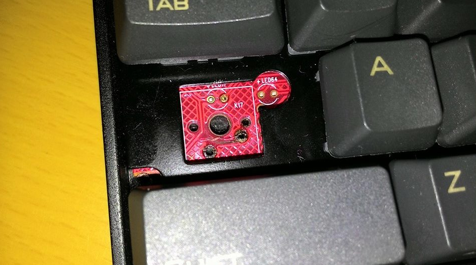
did you heat the traces on the PCB that much, it even scorched the solder on the A,Q and W keys? If yes, then that's where you can patch your CAPS switch - i guess; test it out yourself, bridge out some connections in the matrix and find where capslock gets registered on the pc.
Also check if the part left to the word "CAPS" still has good connections on the board.
PS: Stop using a blowtorch to desolder switches.
Posted: 18 Sep 2015, 20:34
by chzel
From what I gather, this is self assembled custom or a switch swap.
Any more information about the board and pics of the other side of the board will help.
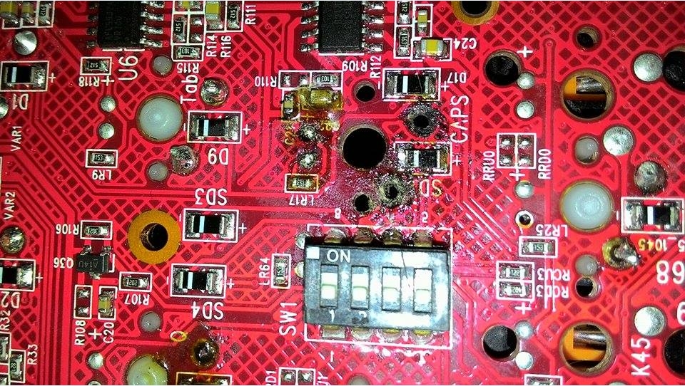
I most likely found one of the pins, check the pic below.
You will need to solder a small wire from the pin of the switch to the side of the diode (that little black rectangular thing).
DO NOT TRY THIS BEFORE YOU GET A DECENT SOLDERING IRON. You will destroy the diode.
Buy a cheap 30-50W iron with a small tip (not a gun, an iron.). Find an old useless PCB and start soldering and desoldering random wires on the components for practice. Don't let the joint heat up to much. If you see the flux (the yellow gooey stuff) turn black like it did on the pics, you are heating the joint too much.
The PCB is already quite damaged but it can be saved (probably). Don't rush it, take your time, practice your skills and we are here to help!
Posted: 19 Sep 2015, 09:56
by REVENGE
1. Clean the damaged areas (medium stiffness brush + 99.9% isopropanol)
2. Rebuild traces
Getting a picture of an undamaged PCB and/or schematic should help you figure out where the traces should go.
Posted: 19 Sep 2015, 14:18
by burn1nsun
Is anyone willing to test where the caps lock activates from on their pok3r?
Posted: 19 Sep 2015, 14:27
by andrewjoy
The traces are on the other side , i cannot see any traces running form the damaged pads , just the ground plane arround them. Ether that or they are both running to ground.
How did that happen ?
Posted: 19 Sep 2015, 14:53
by chzel
In the top pic you can see a trace lifted going from the right pad to a via on the left, and from the other side the via goes to the top of the diode.
The other pad is a mystery. Not enough views to determine where it goes. That's why I'm asking which PCB it is, so hopefully someone can trace the pad on an intact PCB.
My guess is that he used too hot an iron, or possibly a gun (the trigger type) and overheated the PCB. The charred flux is pointing to that direction.
Posted: 19 Sep 2015, 15:42
by burn1nsun
Its a pok3r pcb. It happened while soldering (I didn't solder it).
Also heres a post from geekhack for some info:
I've looked and looked at these pics but got nowhere, I also found this closeup of the area on keychatter and it suggests that neverused was incorrect - the end of the diode suggested appears to be connected to dipswitch 4 rather than the switch pin (I was trying to work out the other pin as I agreed with him!) and neither pin is connected to anything on this side of the PCB.

Reading the manual it seems that the caps lock key needs to be connected to switches 3 and 4 in the block so unlike a standard matrix I don't think it's going to be as simple as connecting the switch to the keys near it, at least if you want to keep those switches working.
I think you need the help of someone with a working pok3r and a multimeter to work this out and I would change the thread title to try and lure someone willing and able in.
Posted: 19 Sep 2015, 19:00
by chzel
So the other pin has a trace on the top side too.
Any chance of a photo from the top? Shot from the Tab side of the top (I don't know if that makes sense, I want to see under the plate between Caps Lock and Shift)