A few more words to describe what I did to revive the Bigfoot. The Arduino software is Soarer_Controller_v1.20_beta4, and I use Ubuntu Trusty 14.04 to compile the tools and to upload the software.
The inspiration came from Laser, and
IBM Model F Bigfoot with arduino micro, win7 64bit. Thanks Laser.
Installation of software tools in Ubuntu:
Code: Select all
sudo apt-get update && sudo apt-get install arduino arduino-core libusb-dev
I use the
Arduino Micro, simply because I happen to have one to hand. Soarer's Controller is written for the Teensy, but it seems that it might operate on any ATMEL based hardware.
Take a snapshot of the TTY devices and the USB devices before plugging in the Arduino:
Code: Select all
ls -1 /dev/tty* > Before-tty
lsusb > Before-USB
Plug in the Arduino and take another snapshot:
Code: Select all
ls -1 /dev/tty* > After-tty
lsusb > After-USB
Show the differences:
Code: Select all
diff Before-USB After-USB
6a7
> Bus 002 Device 017: ID 2341:8037 Arduino SA
diff Before-tty After-tty
65a66
> /dev/ttyACM0
Unpack
Soarer's Keyboard Controller firmware
Code: Select all
mkdir "Soarer's Converter"
cd "Soarer's Converter"
unzip ../Soarer_Controller_v1.20_beta4.zip
tar -zxf Soarer_sctools_v1.20_beta4_linux.tar.gz
This is what the 'tree' command reveals:
Code: Select all
tree
.
├── configs
│   ├── 6112884.sc
│   ├── bigfoot.sc
│   ├── kevex-blank.sc
│   ├── kevex-retrete.sc
│   └── mini_matrix.sc
├── docs
│   ├── controller.html
│   ├── images
│   │   └── bullet.png
│   └── style1.css
├── firmware
│   ├── Soarer_Controller_v1.20_beta4_at90usb1286.hex
│   ├── Soarer_Controller_v1.20_beta4_at90usb646.hex
│   └── Soarer_Controller_v1.20_beta4_atmega32u4.hex
└── tools
    ├── scas
    ├── scboot
    ├── scdis
    ├── scinfo
    ├── scrd
    ├── scwr
    ├── Soarer_sctools_v1.20_beta4_linux.tar.gz
    ├── Soarer_sctools_v1.20_beta4_macosx.tar.gz
    ├── Soarer_sctools_v1.20_beta4_source.zip
    └── Soarer_sctools_v1.20_beta4_win32.zip

5 directories, 21 files
Program the Arduino with the precompiled firmware, specifying the correct device for the -P option, in this example /dev/ttyACM0:
Code: Select all
cd firmware
sudo avrdude \
-p atmega32u4 \
-P /dev/ttyACM0 \
-c avr109 \
-U flash:w:Soarer_Controller_v1.20_beta4_atmega32u4.hex
The 'sudo' part is necessary, otherwise the following error is the result:
Code: Select all
avrdude: ser_open(): can't open device "/dev/ttyACM0": Permission denied
It also may be necessary to add 'dialout' group to the login account, and to log-out and log-in again to make the change take effect:
An example of the output of 'avrdude':
Code: Select all
$> avrdude -p atmega32u4 -P /dev/ttyACM0 -c avr109 -U flash:w:Soarer_Controller_v1.20_beta4_atmega32u4.hex

Connecting to programmer: .
Found programmer: Id = "CATERIN"; type = S
    Software Version = 1.0; No Hardware Version given.
Programmer supports auto addr increment.
Programmer supports buffered memory access with buffersize=128 bytes.

Programmer supports the following devices:
    Device code: 0x44

avrdude: AVR device initialized and ready to accept instructions

Reading | ################################################## | 100% 0.00s

avrdude: Device signature = 0x1e9587
avrdude: NOTE: "flash" memory has been specified, an erase cycle will be performed
         To disable this feature, specify the -D option.
avrdude: erasing chip
avrdude: reading input file "Soarer_Controller_v1.20_beta4_atmega32u4.hex"
avrdude: input file Soarer_Controller_v1.20_beta4_atmega32u4.hex auto detected as Intel Hex
avrdude: writing flash (17726 bytes):

Writing | ################################################## | 100% 1.32s

avrdude: 17726 bytes of flash written
avrdude: verifying flash memory against Soarer_Controller_v1.20_beta4_atmega32u4.hex:
avrdude: load data flash data from input file Soarer_Controller_v1.20_beta4_atmega32u4.hex:
avrdude: input file Soarer_Controller_v1.20_beta4_atmega32u4.hex auto detected as Intel Hex
avrdude: input file Soarer_Controller_v1.20_beta4_atmega32u4.hex contains 17726 bytes
avrdude: reading on-chip flash data:

Reading | ################################################## | 100% 0.14s

avrdude: verifying ...
avrdude: 17726 bytes of flash verified

avrdude: safemode: Fuses OK (H:CB, E:D8, L:FF)

avrdude done.  Thank you.
Soarer's tools, 'scinfo', 'scas' etc are offered with source code. The precompiled tools are 32-bit versions, which don't work on 64-bit Ubuntu unless a pile of 32-bit libraries are installed. I decided to recompile these tools for my 64-bit Ubuntu installation instead:
Code: Select all
cd Soarer_Controller_v1.20_beta4/tools
mkdir SOURCE
cd SOURCE
unzip ../Soarer_sctools_v1.20_beta4_source.zip
cd build/linux
make
Check the result with Soarer's tools:
An example of what to expect:
Code: Select all
cd Soarer_Controller_v1.20_beta4/tools
$> sudo ./scinfo
[sudo] password:
scinfo v1.10
scinfo: looking for Soarer's Converter: found
scinfo: sending info request: ok
device: ok

Protocol Version: v1.00
Code Version: v1.20
Max Settings Version: v1.03
Current Settings Version: v0.00
SRAM Size: 2560 bytes
SRAM Free: 1793 bytes
EEPROM Size: 1024 bytes
EEPROM Free: 1020 bytes
Now to upload the configuration file. The `scaswr.bat` file in the Win32 archive shows what to do. First compile the configuration file to binary using 'scas':
Code: Select all
cd Soarer_Controller_v1.20_beta4/tools/SOURCE/bin
./scas ../../../configs/bigfoot.sc ../../../configs/bigfoot.scb
Example output:
Code: Select all
scas v1.20
No errors. Wrote: ../../../configs/bigfoot.scb
Next, write the compiled configuration to the Arduino with the 'scwr' tool:
Code: Select all
sudo ./scwr ../../../configs/bigfoot.scb
Output:
Code: Select all
scwr v1.10
scwr: looking for Soarer's Converter: ../common/hid_LINUX.c:175, vid=16c0 pid=47d
rawhid_open, max=1
device: vid=16C0, pic=047D, with 4 iface
  type 3, 1, 1
  type 3, 0, 0
    IN endpoint 3
  hid interface (generic)
  descriptor, len=21
  tag: 4, val FF31
  tag: 8, val 74
  type 3, 0, 0
    IN endpoint 2
  hid interface (generic)
  descriptor, len=220
  tag: 4, val 1
  tag: 8, val 6
  type 3, 0, 0
    IN endpoint 4
    OUT endpoint 5
  hid interface (generic)
  descriptor, len=28
  tag: 4, val FF99
  tag: 8, val 2468
found
scwr: reading file: 118 bytes: ok
scwr: sending info request: ok
device: ok
protocol version check: converter=1.00, scwr=1.00: ok
settings version check: converter=1.03, file=1.03: ok
settings length check: max=1018, file=116 bytes: ok
scwr: sending write request for 116 bytes: ok
device: ok
device: ready
scwr: sending 60 bytes: ok
device: ok
device: ready
scwr: sending 56 bytes: ok
device: ok
device: complete
Note that the debugging output is enabled in the example above. In the file tools/SOURCE/common/hid_LINUX.c:
Code: Select all
#define printf(...) // comment this out for lots of info
Connect the Arduino to the
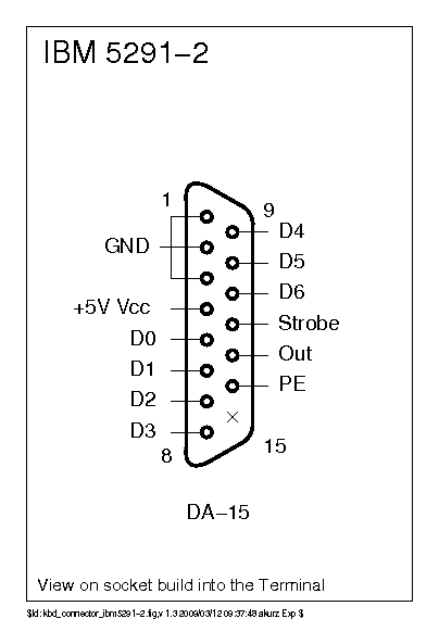
IBM Bigfoot DB15 cable. The second column "Pin" is the IBM pin numbering on the Logic Board. The 5291 Maintenance Library manual shows that the IBM numbering convention is different to IDC convention, so be aware!
Code: Select all
| DB15 Pin | Pin | Duty           | Atmel |
|----------|-----|----------------|-------|
|        1 |  20 | GND            |       |
|        2 |  18 | GND            |       |
|        3 |  12 | GND            |       |
|        4 |  13 | +5V            |       |
|        5 |  17 | Count  1       |   PB0 |
|        6 |   1 | Count  2       |   PB1 |
|        7 |   3 | Count  4       |   PB2 |
|        8 |   4 | Count  8       |   PB3 |
|        9 |   8 | Count 16       |   PB4 |
|       10 |   9 | Count 32       |   PB5 |
|       11 |  10 | Count 64       |   PB6 |
|       12 |  19 | Matrix Strobe  |   PD1 |
|       13 |  11 | +Key Depressed |   PD0 |
|       14 |  14 | Frame Ground   |       |
|          |   2 | Not Used       |       |
|          |   5 | Not Used       |       |
|          |   6 | Not Used       |       |
|          |   7 | Not Used       |       |
|          |  15 | Not Used       |       |
|          |  16 | Not Used       |       |
I used a DB15 socket salvaged from an ancient PC ISA sound card, which had a DB15 joystick port. The pin numbers on that are also rearranged, so I needed to expand the table above:
Code: Select all
| Ribbon | DB15 Pin | Duty           | Atmel pin | Arduino micro pin |
|--------|----------|----------------|-----------|-------------------|
|      1 |        1 | GND            |           |                   |
|      2 |        9 | Count 16       |  28 PB4   | J5-13 IO8         |
|      3 |        2 | GND            |           |                   |
|      4 |       10 | Count 32       |  29 PB5   | J5-14 IO9         |
|      5 |        3 | GND            | PAD GND   | J6-04 GND         |
|      6 |       11 | Count 64       |  30 PB6   | J5-15 IO10        |
|      7 |        4 | +5V            |  34 +5V   | J6-06 +5V         |
|      8 |       12 | Matrix Strobe  |  19 PD1   | J5-07 D2/SDA      |
|      9 |        5 | Count  1       |   8 PB0   | J5-02 RXLED/SS    |
|     10 |       13 | +Key Depressed |  18 PD0   | J5-08 D3/SCL      |
|     11 |        6 | Count  2       |   9 PB1   | J6-01 SCK         |
|     12 |       14 | Frame Ground   |           |                   |
|     13 |        7 | Count  4       |  10 PB2   | J5-01 MOSI        |
|     14 |       15 | Not Used       |           |                   |
|     15 |        8 | Count  8       |  11 PB3   | J6-02 MISO        |
The complete picture of connections to the Arduino:
Code: Select all
Ribbon           Duty   Atmel    Arduino           Arduino   Atmel  Duty       Ribbon
                                         +-------+
    13       Count  4     PB2       MOSI |#      | SCK       PB1    Count  2   11
     9       Count  1     PB0   RXLED/SS |       | MISO      PB3    Count  8   15
                          PD3      D1/TX |       | VIN
                          PD2      D0/RX |       | GND              Frame+GND  5+12
                                   RESET |       | RESET
   1+3         Ground                GND |       | 5V               +5V         7
     8  Matrix Strobe     PD1         D2 |       |
    10  Key Depressed     PD0         D3 |       |
                          PD4         D4 |       | A5        PF0
                          PC6         D5 |       | A4        PF4
                          PD7         D6 |       | A3        PF4
                          PE6         D7 |       | A2        PF5
     2       Count 16     PB4        IO8 |       | A1        PF6
     4       Count 32     PB5        IO9 |       | A0        PF7
     6       Count 64     PB6       IO10 |       | AREF
                          PB7       IO11 |       | 3V3
                          PD6       IO12 |       | IO13      PC7
                                         +-------+
The result:
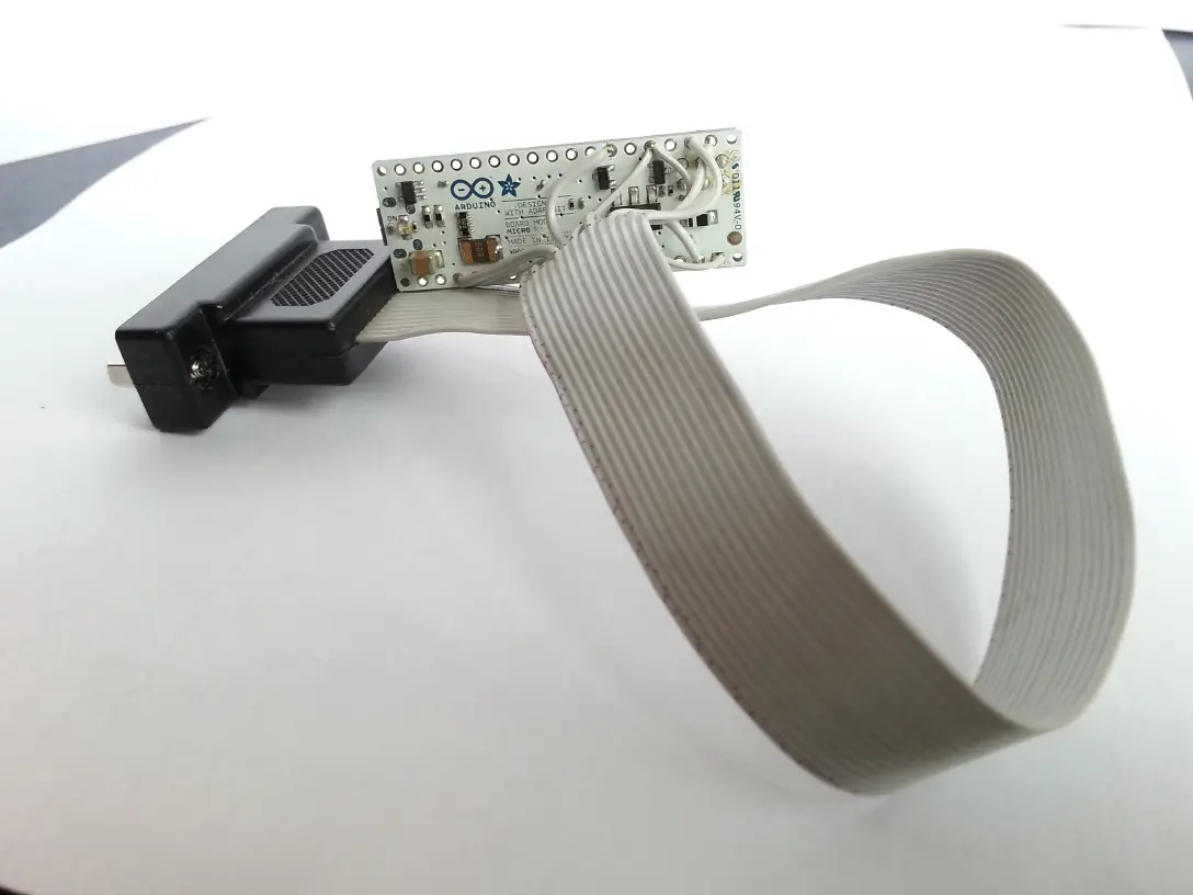
- DB15-ribbon-arduino.jpg (178.49 KiB) Viewed 4510 times
I have a collection of photos showing the internals of the Bigfoot. These were taken while cleaning, and reassembly photos show how I reinserted the space bar with the help of dental floss and a spanner. Photos will follow soon that will reveal how that odd combination worked.
Soarer explains that the IBM Bigfoot contains only a demultiplexer and a cap-sense chip, and no microcontroller. There's no need to rip any of the original electronics out to be replaced by the Arduino/Teensey, just connect to the original DB15 and cable, or plug directly into the 20-pin IDC connector on the Keyboard Logic Card (as it is called in the
5291 Maintenance Library manual for the IBM terminal).
I found another discussion about adapting the
Xwhatsit Grand Unified IBM Capsense USB Controller to be
used on the IBM Bigfoot. It seems that the lack of microcontroller was not noticed there. In effect, the Xwhatsit controller hardware also has a demultiplexer, and uses the ATMEL analogue comparator inputs to detect keypresses. The IBM Bigfoot provides this, and potentially the Xwhatsit ATMEL controller software code could be used after minor edits. I may try that to replace Soarer's Controller software.


