HID Liberation Device - DIY Instructions
Jump to navigation
Jump to search
This design has been superseded by newer developments. Please see the Costar replacement controllers page instead.
Very important: The footprint for the electrolyte is backwards. Make sure you mount it the correct way around (that is opposite to the silk screen printing), or leave it out altogether! The black band should be located like in the image to the right
Contents
Notice
This will be the instruction guide for the HID Liberation Device DIY kit.
Hardware
These are the exact components included in the original kit.
| Amount | Description | Manufacturer part number |
|---|---|---|
| 1 | HID Liberation Device circuit board | |
| 1 | ATmega32u4 micro controller | ATMEGA32U4-AU |
| 1 | 3-8 Decoder Logic IC | CD74HC238M96 |
| 1 | 16MHz crystal oscillator 3.2 x 2.5 mm | ABM8G-16.000MHZ-4Y-T3 |
| 2 | 18pF 0603 ceramic capacitors | C1608C0G1H180J |
| 5 | 100nF 0603 ceramic capacitors | C1608X7R1E104K |
| 3 | 1µF 0603 ceramic capacitors | C1608X7R1C105K |
| 1 | 10µF 4.3 x 5.5 mm electrolytic capacitor | EEE-1CA100SR |
| 2 | 22Ω 0603 resistors | ERJ-3GEYJ220V |
| 21 | 10kΩ 0603 resistors | ERJ-3GEYJ103V |
| 1 | Magnetic "Reed" switch | KSK-1A87-1015 |
| 2 | 8-pin headers, 2mm pitch |
Tools needed
- Soldering iron
- Solder
- Wire cutter to cut off component pins
Step-by-step instruction:
- Clean the PCB with rubbing alcohol. Even if you didn't put your sticky fingers onto it, bpiphany probably did.
- Start with the side saying "HID Liberation Device".
- Release the 10kΩ resistors from their tape, and make sure not to lose them.. There should be four spare ones included so it is a good idea to start with these to get up to speed.
- (See video below for 0603 resistor soldering)
- Tin the pads along the edges (the inner ones are connected to the ground plane and take more heat).
- Tack down all 10kΩ resistors to the tinned pad. (The LED series resistors are 10kΩ as well.)
- Also find the 22Ω resistors and tack them to their pads.
- Make sure all resistors are straight and centered on the footprints.
- Solder the inner pads of all resistors.
- Apply flux to the outer pads, and solder them properly.
- Flip the board over.
- (See video below for soldering the crystal)
- Start out with the crystal, it can be tricky to get at with other components in the way. The long and short edges need to be oriented correctly, but it is 180° rotationally symmetric.
- (See video below for soldering the ATmega)
- Tin one pad of both the ATmega controller and the 3to8 decoder. Same as with the resistors, pick a pad that does not look like it is connected to the ground plane.
- Solder the decoder first. It has less pins, with wider pitch, and makes for good practice.
- Tack the decoder down and make sure it sits straight and centered. Apply flux to all joints and solder them properly.
- Repeat the same procedure for the controller. Pin 1 and 8 are left unsoldered.
- Tin one pad for each of the 0603 components.
- Start with the remaining 10kΩ resistor.
- Proceed with the 100nF capacitors. There should be 1 extra included to allow for a single screw up.
- Finish off the 0603 components by soldering the three 1µF capacitors.
- Very important: Observe that the silk screen printing for the electrolytic capacitor is backwards. Be sure to solder it the correct way around.
- Put some tin onto the anode of the 10µF capacitor.
- Apply flux to the footprint and capacitor leads.
- Heat the solder up and slide the capacitor in place. This takes a fair amount of heat.
- Heat the opposite pad and component lead, and apply solder. It is possible to feed a good amount of solder on to the joint. Some of it will flow into the through hole.
- Flip the board over again.
- Fill up the through hole pads of the 10µF capacitor and the crystal to make sure their connections are good.
- Put the pin headers in place one at a time. Insert their short end from the controller side. Doing this wrong is a real pain to try to fix.
- Solder one of the pins, making sure the row of pins is seated properly.
- Solder the rest of the pins, making sure they are seated all the way.
- Bend the leads of the Reed switch to fit between the reset pad on the ISP connector and the GND hole next to pin 8 of the decoder.
- Insert the Reed switch from the controller side. It is recommended to not have it mounted flush to the PCB. Bend the leads on the other side of the PCB with some distance between the PCB and the switch housing.
- Flip the board over and solder the Reed switch. The bends in the leads should keep the switch hanging a small distance below the PCB. Trim the leads.
- Clean up the flux residues.
- You are done =D
Videos
Soldering the TQFP44 ATmega32u4
Firmware
- Official firmware source code: https://github.com/BathroomEpiphanies/HID-Liberation-Device
- Hasu's tmk_keyboard firmware source code: https://github.com/tmk/tmk_keyboard
- Easy AVR Firmware
Flashing the controller
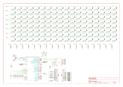
Schematic

