Beamspring USB controller

User avatar
Muirium
µ

31 Mar 2014, 12:28

quantalume wrote:
Muirium wrote:Ah, Honeywells. I have a few of those, too, but they're all in this keyboard:

http://deskthority.net/photos-videos-f8 ... t6296.html
Ah, very nice. I once had a similar Honeywell keyboard, but somewhat smaller and without any encoding circuitry. Sadly, it's long gone. :cry:
How do you use them, electrically speaking?
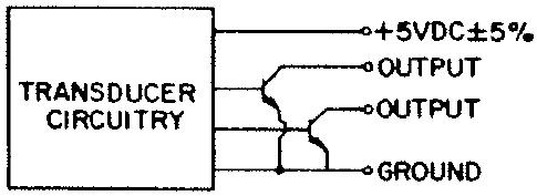
Two of the four pins go to the power supply, and the other two pins are open collector outputs, like this:
Image
The pair of open collector outputs were essentially an open circuit when the key wasn't pressed. so you could wire them together in standard matrix fashion.
And do you fancy sharing a few spares with the community? I know plenty of people who'd love to try one of this legendary smooth linear switch.
I doubt I have enough to supply all interested parties, but what would you think about creating a roving package of unusual and/or out-of-production switches? I could contribute one assembled and one disassembled Honeywell switch, like this one:
Image
One neat feature of this design was the self-adhesive, double-sided tape on the bottom plate. This allowed one to stick the switch in place while the PCB was turned over and soldered.
Great info, Quantalume. Thanks. I suspected these guys needed AC of some sort, like a transformer, but they're smarter than that fortunately! Know if they still need diodes for an NKRO matrix? I hear my Honeywell has poor rollover, but I don't know if this is the matrix or controller's fault.

I've been adding weird old switches of my own to the sample box I bought from Mr. Interface last year. Perhaps I should get into the touring racket with you!

xwhatsit

31 Mar 2014, 22:25

Muirium wrote:Know if they still need diodes for an NKRO matrix? I hear my Honeywell has poor rollover, but I don't know if this is the matrix or controller's fault.
Being open-collector outputs, no you won't need diodes—you only need that on standard `ohmic switching' (IBM patent language :lol: ) matrices, as you end up with a conductive loop which can short-circuit some keys and make them appear live.

Those Honeywell switches (gosh they must have been high-end at the time!) therefore support proper NKRO, the same as a capacitive matrix, so if your controller supported it you could hold down all the keys and have them all register individually, just the same as the USB beamsprings.

Very cool! Must have cost a fortune at the time.

quantalume

04 Apr 2014, 22:57

I sent a controller to Revenge today and still have the parts for another. I was thinking of keeping it in case I come across another keyboard, but if someone really wants it, just let me know. I also have an additional 7 connectors left over.

Since we're such a small and elite group, I think us beamspringers should start a secret society, complete with secret hand signs, funny hats and a coat of arms. :lol:

xwhatsit

06 Apr 2014, 06:59

Awesome!

Yes we will need a secret society. I just bought 4 Selectrics (one I, three IIs, and also a very strange Swiss knockoff—the Hermes 808), it looks like I'll have to join some kind of strange society for that too (probably a psychiatric ward).

The Selectrics and their marvellous banging inspired me to finish off the solenoid driver:

Schematics:
solenoid-driver.pdf
(30.98 KiB) Downloaded 183 times
Top:
Image

Bottom:
Image

This was slightly more difficult than I intended. Once I started doing the sums I realised that it's really pushing the USB power spec to the limits. I was initially going to use the horrible old (cheap and available!) MC34063 switch-mode controller chip to get the 8–9V necessary, but it requires rather a lot of bypass capacitance on the input, and that is a big problem!

Because USB is hot-pluggable, they specify a max of 10uF bypass capacitance across Vbus and GND to stop the 5V sagging down too low on the other ports when you plug something in and all the caps charge up. With the controller board itself, we already have a nice juicy 4.7uF cap on there, plus one or two dozen 100nF local bypass caps scattered around like candy. The MC34063 usually wants a good 100uF or so (!); more modern switchers still typically want at least 10uF.

Making life even more difficult, one is only allowed to suck up to 100mA until you negotiate higher during enumeration. Ignoring the bypass caps, charging up the caps on the other side of the switcher is going to suck some juice for a little while too.

However there's a chip for that. Actually there's quite a few, but I used Micrel's MIC2009A. They are current-limited power switches; you set the current limit (about 400mA in this case) with a resistor. At first it's turned off, so the boost power supply is not running at all and we should be well below the 100mA limit. After the beamspring controller has negotiated over USB that it wants the full 500mA, we turn on the power switch with the enable pin. The current-limited soft start phase begins, the boost converter starts doing its thing and charging up the big output cap, and we're ready to go.

The MIC2250 switcher is a nice one; it runs faster than the old MC34063, so we don't need such a huge inductor, and it has a cool feature where it `dithers' the frequency to spread the noise out a bit over the spectrum, cutting down on EMI. I'm still a bit worried about interference with the capsense stuff. We will see.

I've used a big old ULN2003 relay driver with all of the darlingtons wired up in parallel, which is major overkill. It's old-school (a lot of voltage drop across two BJTs), but is cheap and effective. It even has flyback diodes built in which is handy.

I'm a bit unsure about the sums: the MIC2009A isn't very precise with its current limiting, could be anywhere between 320mA and 560mA despite me setting it to 430mA, and the amount of current RMS required to flail the solenoid at a higher duty cycle with somebody mashing the keys really quickly is obviously a bit of a guess. I think holding the solenoid in at 100% duty cycle could be beyond the limits of the 500mA interface; I think it wlil be about 240mA at 8V, and the MIC2250 switcher, although pretty efficient, isn't *that* good. However we don't want to turn on the solenoid constantly, I think a nice `clickick' smack/release like a Selectric would be quite pleasant.

REVENGE

06 Apr 2014, 09:14

quantalume wrote:I sent a controller to Revenge today and still have the parts for another. I was thinking of keeping it in case I come across another keyboard, but if someone really wants it, just let me know. I also have an additional 7 connectors left over.

Since we're such a small and elite group, I think us beamspringers should start a secret society, complete with secret hand signs, funny hats and a coat of arms. :lol:
:D Thank you kind sir, quantalume is a gentleman and a scholar!

User avatar
Game Theory
Mr. Despair

06 Apr 2014, 15:55

xwhatsit wrote: I think a nice `clickick' smack/release like a Selectric would be quite pleasant.
Agreed!

mr_a500

07 Apr 2014, 01:48

xwhatsit wrote:The Selectrics and their marvellous banging inspired me to finish off the solenoid driver:

Top:
Image

Bottom:
Image

Excellent.png

woody
Count Troller

07 Apr 2014, 10:14

xwhatsit wrote:... solenoid driver ...
Why not play it safe and provide a separate connector for the solenoid power, then use cheap wall wart adapter?

xwhatsit

07 Apr 2014, 10:37

Yeah I thought about that but that would be my last choice. Wallwarts are a pain at the best of times, let alone being a second cord coming out the back of your keyboard, having to route over my desk down to a multiadaptor. If this doesn't work out, I'll go down that route; it would be a significantly simpler board and pretty quick to knock out.

REVENGE

07 Apr 2014, 12:03

xwhatsit wrote:Yeah I thought about that but that would be my last choice. Wallwarts are a pain at the best of times, let alone being a second cord coming out the back of your keyboard, having to route over my desk down to a multiadaptor. If this doesn't work out, I'll go down that route; it would be a significantly simpler board and pretty quick to knock out.
If you use a secondary power source, you could include a second USB connector to pull power from a second port or USB chargers.

xwhatsit

07 Apr 2014, 12:14

You see that on a lot of optimistic 2.5" HDD->USB converters. Unfortunately it's not as effective as you might think; remember, to get 500mA, you need to negotiate for it, otherwise the USB host is usually quite happy to limit you to 100mA.

Secondly, especially on little SBCs (what I use at work) and with laptops etc. (very similar tech), you'll find that the Vbus and Gnd are simply bridged together across upwards of two ports. Taking power from two ports doesn't necessarily give you double the current of a single port.

To be honest I could probably skip the current limited switch (the MIC2009A) and you'd find that it would work fine on 9/10 desktops. However I'd hate to build something that falls over the moment you plug it into a laptop, or one of those dinky wee Intel NUCs. Hence wanting to stick to the spec.

I think it should work, in the worst case it might be duty-cycle limited (i.e. how many times per second the solenoid fires). Could always provide a connector for a wee li-ion RC model battery :)

User avatar
bhtooefr

07 Apr 2014, 12:52

The other thing is, what about designing the world's first USB 3 keyboard that doesn't have a hub?

Then you get 150 mA while negotiating for power (which is the native USB 3 power unit), and 900 mA after negotiation.

REVENGE

08 Apr 2014, 04:43

IT'S ALIVE!!!

Although there is something quirky going on with the key map and Tab is not sending key up, I'm typing the body of this post using my 3727! This board is so clean, I won't even bother with replacing the contamination shield for the time being.

Thanks again quantalume and xwhatsit! 8-)

xwhatsit

08 Apr 2014, 05:14

Awesome!

If the tab you have it mapped to is genuinely the tab which that node in the matrix is hooked up to on the 3727, then it sounds like you might need to strip your board down and clean it.

I too have a 3727 and thought that the contamination shield was good—eventually I was getting crazy keys firing unexpectedly. I stripped the keyboard down and found that there were bits of contamination shield flaked off between the key modules and the sense board pads.

Thinking that I have a 3727—I shall attach my current matrix file here, you can try importing it and see what happens.

...well I was going to attach it but the forum says `The extension l is not allowed'. It also says that for txt. :|

Download here: http://downloads.cornall.co/3727_layout.l

REVENGE

08 Apr 2014, 07:28

Thanks for the tips! I would like to replace the contamination shield with new material, but I must order a decent key cap puller.

Also, I see exactly what you meant regarding the spacers under the blank keys. Once I removed it, the key functioned normally.

By the way, my 3727 has a similar heritage to yours. It was manufactured at a similar time and was also property of IBM in Armonk, NY. So in case they come looking for their property... :?

REVENGE

08 Apr 2014, 11:29

xwhatsit wrote:I stripped the keyboard down and found that there were bits of contamination shield flaked off between the key modules and the sense board pads.
I think that is what happened. The exact bug was such that Tab didn't fire at all, while Ctrl fired key down, but Tab key up was fired on release.

Although I only found a piece of debris the size of a grain of sand, removing it cleared up the problem.

EDIT: Has anyone tried to remove the return spring from the dummy module under the space bar?
Last edited by REVENGE on 08 Apr 2014, 13:55, edited 1 time in total.

User avatar
bhtooefr

08 Apr 2014, 12:11

These things are INCREDIBLY sensitive to debris on the PCB. Best bet is to remove the PCB and clean it off with high-percentage isopropyl alcohol, on both sides, I'd say, then allow it to dry before reinstalling it.

REVENGE

08 Apr 2014, 13:56

bhtooefr wrote:These things are INCREDIBLY sensitive to debris on the PCB. Best bet is to remove the PCB and clean it off with high-percentage isopropyl alcohol, on both sides, I'd say, then allow it to dry before reinstalling it.
Yes, that was exactly what I did and it seems to have done the trick nicely.

Now for this heavy space bar...

xwhatsit

08 Apr 2014, 22:44

I've heard about heavy spacebars on some beamsprings but I can't say I have that on either my 3727 or my (admittedly worn-out) 5251.

I have a PC-AT Model F with its infamous heavy spacebar and that is undeniably noticeable. My 3727 requires a slight extra amount of force compared to a normal key, but that would be the case even on those Cherry keyboards the proletariat are satisfied with. Even on my cow-orker's Topre the good feeling of oneness with cup rubber isn't uniform—one requires a little bit more good feeling to depress the spacebar.

As far as I can see there's just a wire stabiliser and a `dead' key (or was it two?) with just a spring in it. As long as the wire stabiliser is adequately lubricated on its journals, and there's no interference from the case (you have to be careful when reassembling the top cover) there's no reason why it shouldn't be very comfortable.

User avatar
wheybags

08 Apr 2014, 22:59

This is never gonna happen, but I don't suppose anyone has a beamspring they're looking to sell?
I dearly desire to acquire one :(

REVENGE

09 Apr 2014, 04:37

xwhatsit wrote:As far as I can see there's just a wire stabiliser and a `dead' key (or was it two?) with just a spring in it. As long as the wire stabiliser is adequately lubricated on its journals, and there's no interference from the case (you have to be careful when reassembling the top cover) there's no reason why it shouldn't be very comfortable.
I really prefer light spacebars, so being able to remove the return spring from the 'dead' key would be a huge bonus for me. As far as I've searched, I've seen no further disassembly of the beamspring module than removing the fly plate.

User avatar
E TwentyNine

10 Apr 2014, 00:38

REVENGE wrote:
xwhatsit wrote:As far as I can see there's just a wire stabiliser and a `dead' key (or was it two?) with just a spring in it. As long as the wire stabiliser is adequately lubricated on its journals, and there's no interference from the case (you have to be careful when reassembling the top cover) there's no reason why it shouldn't be very comfortable.
I really prefer light spacebars, so being able to remove the return spring from the 'dead' key would be a huge bonus for me. As far as I've searched, I've seen no further disassembly of the beamspring module than removing the fly plate.
I think if you pulled the o-ring off first you may be able to maneuver the spring so it can be removed.

User avatar
Compgeke

10 Apr 2014, 06:35

One problem I see with removing that spring is you basically remove the switch stabilizer as far as I can tell. Possibly replacing the springs with lighter springs would work.

xwhatsit

10 Apr 2014, 10:57

First Rev4 all assembled and humming along nicely (I had to thieve a ATmega32U2 from another piece of equipment—swapped it for an 8U2—my damned eBay 32U2s still haven't arrived, lazy Americans and their postal system!):
photo 1.JPG
photo 1.JPG (127.96 KiB) Viewed 7635 times
photo 2.JPG
photo 2.JPG (138.77 KiB) Viewed 7635 times
The AHC-series shift registers seem to have given a little bit more headroom, which is what the aim was by moving to them; autocalibrate is coming out with some bigger numbers than the Rev3 boards, which means there's more space between pressed keys and unpressed keys. I might be able to get things even nicer, as I have hooked up both the output-enable and storage register strobe lines for the 595 shift registers, so might be able to get a slightly snappier pull-down on the other channels instead of leaving things floating for periods with the 4094s. Bodes well for a Model F when I get around to that. Also means I can crack ahead with the Displaywriter board when I get a moment!

I don't have the parts or the boards for the solenoid driver yet, but you can see the header P2 for the external interfacing to it. I made a balls-up with the solenoid driver board, and swapped the pins for power enable and solenoid drive; this means I'll have to handle the solenoid timing in software instead of using the timer compare output to do it for me. Either that or I don't use a ribbon cable and just hook up individual wires, in which case I can swap the pins.

Oh yeah and much nicer assembly with this board being single-sided. Only one trip through the oven!

mr_a500

10 Apr 2014, 11:56

xwhatsit wrote:First Rev4 all assembled and humming along nicely (I had to thieve a ATmega32U2 from another piece of equipment—swapped it for an 8U2—my damned eBay 32U2s still haven't arrived, lazy Americans and their postal system!)
I thought you said you ordered the 32U2s from Canada. Never call a Canadian an American. It's like calling a New Zealander an Australian. (..but far worse)

Our postal system does suck though - badly.

xwhatsit

10 Apr 2014, 12:01

I know the difference, fellow Commonwealth member!

The 32U2s left Canada very quickly and are now sitting in a sorting office somewhere in New York :(

mr_a500

10 Apr 2014, 12:10

Whew. You scared me there for a second. :P

Yeah, damn those lazy Americans. (...though there are some damn lazy Canadians too :D)

One thing I don't understand - if it's going from Canada to New Zealand, what the hell is it doing in a New York sorting office? It should be sorted in Canada, then put on a plane to New Zealand.

xwhatsit

14 Apr 2014, 04:38

OK so have done a board for the beamspring Displaywriters.

Following in the footsteps of the Rev3..4 standard beamspring boards, I have used the same flat-mounting edge connector design. I've done that simply for consistency, the ability to use both solder-lug and pin versions of the connector, and ease of soldering.

Top:
Image

Bottom:
Image

The only thing is, the Displaywriter actually mounts with the controller at 90° (images stolen from Webwit's website—here comes the ban hammer):
Image

It looks like there is enough room in the case:
Image

...but that's just a guess.

I think in total the board will be about 40mm max high, including the connector depth. If anybody has a Displaywriter and is able to tell me, please let me know. Otherwise I will modify it to use the 90° system.

Cheers.

quantalume

14 Apr 2014, 06:38

So what do you plan to drive the speaker with? :lol: Did the original unit click or beep?

xwhatsit

14 Apr 2014, 06:42

I don't know!

I've put the same P2 3x2 header with the same pinout on the board that the standard beamspring controller has. It would be pretty straightforward to build a small amplifier board, in the same vein as the solenoid driver board; would be much simpler, as you wouldn't need anything more than 5V for starters. Not quite sure what it would do :)

Post Reply

Return to “Workshop”