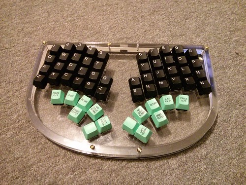
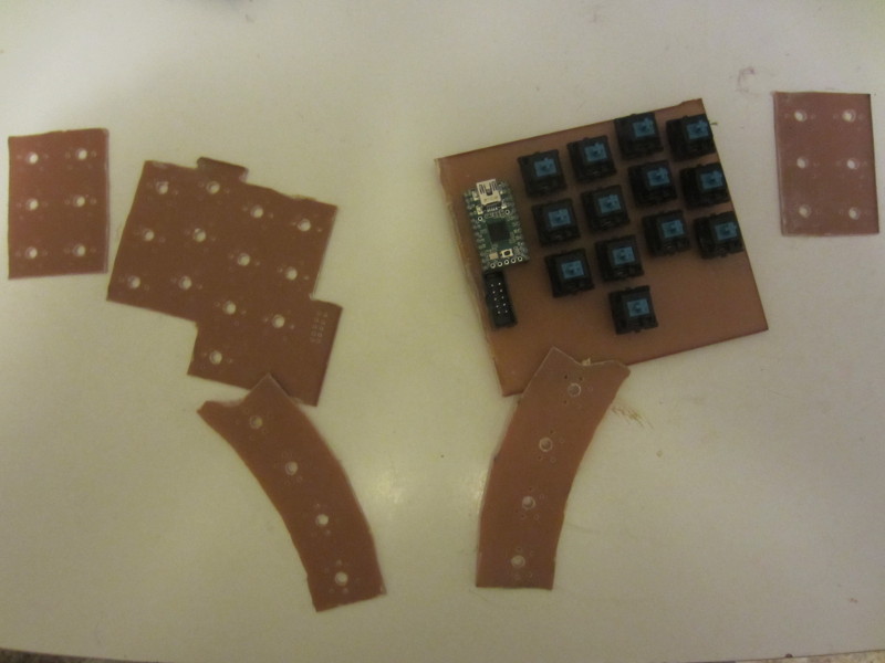
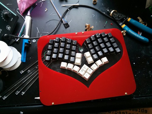
philpirj wrote:jesse: Go my acrylic plate being cut. Switches with caps fit nicely, material is really nice (besides being too electrostatic and collecting all the dust and hairs in the room). Need to desolder my textolite version and solder switches to this plate and bend it. Hopefully will be done by this weekend.
Presumably, you'll bend it before soldering

philpirj wrote:
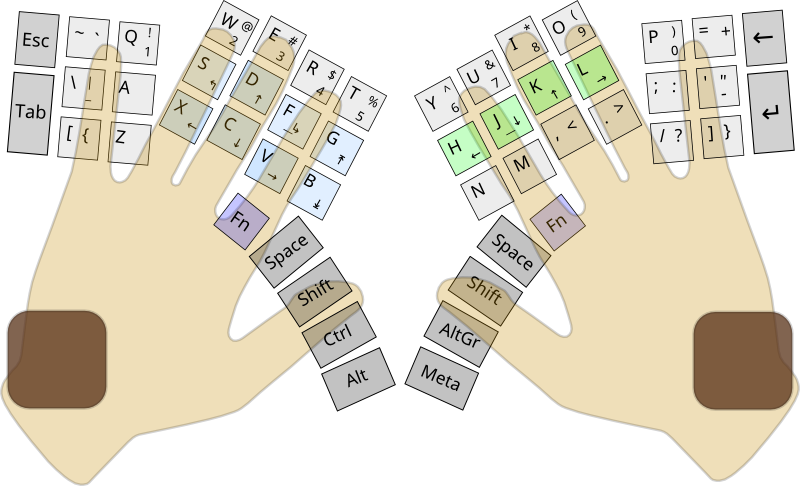
By the way. I disregarded all the advises on putting a 5mm+ spaces between holes and did a 4mm (-0.2mm additional space reduction when laser cutting) space between switches. Caps sit nicely and don't even try to touch each other.
Yeah, I've been using a 4mm spacing and have been quite happy with it. It's at the lower end of the OSHA guidelines, but is still compliant
philpirj wrote:
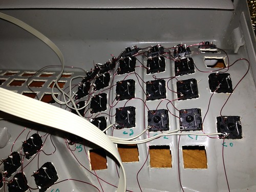
Any advice on soldering the switches inserted in acrylic plate? Should i put a paper so the solder doesn't drop and melt acryl?
That hasn't been a problem for me. I do end up with some drops of solder on the the acrylic, but it's merely ugly. Getting paper into and out of those 4mm channels is going to be a pain, especially after you have a nest of wire on top of em.
What I've been doing lately is clipping the side of the diode that should touch the switch to the length of the lead coming out of the switch and soldering vertically. It eats more vertical space but seems relatively easy to solder, especially with good tweezers.
I switched from soldering the leads on the diodes directly to each other to create the matrix. That turned out to be relatively brittle. Instead, I've been using 30 gauge wire with relatively thin insulation and using a drop of solder to melt away the insulation and solder to the leads. Piers pointed me at using self-fluxing magnet wire as a potentially better option.
http://www.bofh.org.uk/2013/03/13/fun-with-solder writes up his experience on that.
Be sure to leave a decent amount of slack in the wire between keys. Otherwise even a little bit of flexing will snap your solder joints.
I've then been soldering one of these:
https://www.sparkfun.com/products/9194 to each row and each column and connecting those to the Teensy.
The acrylic plate won't hold switches in place very well by itself. Pulling a keycap, even with the best technique, _will_ rip out a switch occasionally. Initially, I tried using superglue to bond switches in place. That mostly works, but enough sneaks into the switches that they develop an uncomfortable scratchy feel. Lately, I've switched to laying down a hotglue matrix once I get the switches in. So far, it's "good, not double-plus amazing" Once I get the 3D printer, I think I'm going to try to make a second plate that goes _over_ the switches to keep them well anchored.
I really need to write this stuff up.


