Let's create the FSSK/FEXT = DONE !!!!

User avatar
idollar
i$

24 Aug 2015, 21:59

I placed the plastic separation between the membranes on top and painted with pencil the contours.
DSC_3290.jpg
DSC_3290.jpg (500.26 KiB) Viewed 5275 times
I also placed the plastic foam on top and painted in red the holes
DSC_3292.jpg
DSC_3292.jpg (392.54 KiB) Viewed 5275 times
The details follow:
DSC_3291_01.jpg
DSC_3291_01.jpg (334.42 KiB) Viewed 5275 times
DSC_3291_02.jpg
DSC_3291_02.jpg (163.58 KiB) Viewed 5275 times
DSC_3291_03.jpg
DSC_3291_03.jpg (136.97 KiB) Viewed 5275 times
DSC_3291_04.jpg
DSC_3291_04.jpg (122.58 KiB) Viewed 5275 times

User avatar
idollar
i$

24 Aug 2015, 22:01

My conclusions are:

1.- Some missing holes
2.- Some error in the printing. Small
3.- Some errors in the position of the holes. The error is bigger than the printing error.

I guess that I need to learn how to create the PCB file, if not, the process will take ages.
My problem again is that I am very busy at present.

User avatar
idollar
i$

24 Aug 2015, 22:03

Regarding the errors comparison:

in this picture, if the border of the plastic is compared with the position of the hole, one can see that the displacement errors do not match

Image

On the other hand, the hole error (red) is matching the printing error ... I cannot conclude if it is correct or not.

User avatar
idollar
i$

24 Aug 2015, 22:11

I also conclude that for the prototypes, it is not recommendable to order the PCBs with the holes done.
One can always drill them with enough precision.

This will remove a potential failure mode. I many PCBs are required after the initial prototypes (I do not think that this will be the case) they could be added later.

User avatar
Muirium
µ

24 Aug 2015, 22:38

Sterling work, i$. I'm in no rush anyway as my barrel frame is in America while my SSKs are all in Scotland! I'm many months away from getting things together even if I wanted.

User avatar
wcass

24 Aug 2015, 23:06

idollar wrote: I also conclude that for the prototypes, it is not recommendable to order the PCBs with the holes done.One can always drill them with enough precision.
Sure, we can silkscreen where we think they should go.

Would you please try the paper template on the back plate to check for that hole above F1? I know that is not correct. I need to get closer as I want to use it for grounding.

Thanks

User avatar
XMIT
[ XMIT ]

24 Aug 2015, 23:11

Sorry, it looks like idollar beat me to the punch here, as I was looking to print these out in the office. Ah well. Maybe I can be of help some other way.

User avatar
Techno Trousers
100,000,000 actuations

24 Aug 2015, 23:21

XMIT wrote:Sorry, it looks like idollar beat me to the punch here, as I was looking to print these out in the office. Ah well. Maybe I can be of help some other way.
If you're still willing, it might be worthwhile to make a second set of measurements just to double-check. Measure twice and drill once, you know...

User avatar
idollar
i$

24 Aug 2015, 23:24

XMIT wrote: Sorry, it looks like idollar beat me to the punch here, as I was looking to print these out in the office. Ah well. Maybe I can be of help some other way.
:mrgreen:

User avatar
idollar
i$

24 Aug 2015, 23:47

wcass wrote:
idollar wrote: I also conclude that for the prototypes, it is not recommendable to order the PCBs with the holes done.One can always drill them with enough precision.
Sure, we can silkscreen where we think they should go.

Would you please try the paper template on the back plate to check for that hole above F1? I know that is not correct. I need to get closer as I want to use it for grounding.

Thanks
Alright: The following pictures are bad quality. The tripod is stored back. I was on my way to bed :-(

I have placed the paper on the back of the metal plate. Looking down. Using the "pencil" technique that we all used when kids to copy coins I marked where the screws are. I then made holes with the top of the pencil to see where they were.
The results follow:

There is some lateral displacement:
Photo 24-08-15 23 27 47.jpg
Photo 24-08-15 23 27 47.jpg (833.4 KiB) Viewed 5229 times
Photo 24-08-15 23 28 04.jpg
Photo 24-08-15 23 28 04.jpg (886.84 KiB) Viewed 5229 times
Photo 24-08-15 23 28 16.jpg
Photo 24-08-15 23 28 16.jpg (710.04 KiB) Viewed 5229 times
More details follow:
Photo 24-08-15 23 36 10.jpg
Photo 24-08-15 23 36 10.jpg (1007.44 KiB) Viewed 5229 times
Notice the lateral displacement again. I have folded the paper and marked the fold with a dashed line
Photo 24-08-15 23 36 10-small.jpg
Photo 24-08-15 23 36 10-small.jpg (658.54 KiB) Viewed 5229 times
Photo 24-08-15 23 36 17-small.jpg
Photo 24-08-15 23 36 17-small.jpg (972.64 KiB) Viewed 5229 times
Photo 24-08-15 23 36 22-small.jpg
Photo 24-08-15 23 36 22-small.jpg (832.68 KiB) Viewed 5229 times

User avatar
idollar
i$

24 Aug 2015, 23:58

My updated conclussions:

1_ We need to ensure that the printout has no error
2_ It will be simpler if I work the file locally. I will PM you wcass

cinnamonrollz

26 Aug 2015, 04:44

I only have fullsized model m's but I would be interested in one of the prototype pcb's. If they work, this would be an awesome design.

User avatar
idollar
i$

26 Aug 2015, 12:06

cinnamonrollz wrote: I only have fullsized model m's but I would be interested in one of the prototype pcb's. If they work, this would be an awesome design.
If the FSSK works, doing the FEMK (F Extended model M Keyboard) should be trivial.
The only issue, once more, are the F flippers that one need to source someone. But we will deal with this latter. One problem at a time is enough.

User avatar
Muirium
µ

26 Aug 2015, 12:42

Too many acronyms!

Apparently, Unicomp still has spare SSK barrel frames in stock, after all these years. Those should all be the last revision of IBM's design, and a known starting point. Could be a good idea to prototype this mechanism with one of them.

User avatar
chzel

26 Aug 2015, 13:11

Shhh...not even Unicomp know they have them!

User avatar
Muirium
µ

26 Aug 2015, 13:14

True, and yet we got two! Perhaps the lack of self awareness is why they still have any.

Vizir

26 Aug 2015, 16:24

idollar wrote:
cinnamonrollz wrote: I only have fullsized model m's but I would be interested in one of the prototype pcb's. If they work, this would be an awesome design.
If the FSSK works, doing the FEMK (F Extended model M Keyboard) should be trivial.
The only issue, once more, are the F flippers that one need to source someone. But we will deal with this latter. One problem at a time is enough.
You could source them from Ellipse's new F62/77 project.

User avatar
idollar
i$

26 Aug 2015, 16:25

Vizir wrote: You could source them from Ellipse's new F62/77 project.
I know. This was my message between the lines.

Vizir

26 Aug 2015, 16:26

idollar wrote:
Vizir wrote: You could source them from Ellipse's new F62/77 project.
I know. This was my message between the lines.
Ah, got it. :)

User avatar
hammelgammler
Vintage

09 Sep 2015, 23:05

Any news with the project?
Oh yeah, do you plan a PCB with windows keys between CTRL and ALT? Or exactly the normal SSK layout? :)

User avatar
idollar
i$

09 Sep 2015, 23:12

hammelgammler wrote: Any news with the project?
Oh yeah, do you plan a PCB with windows keys between CTRL and ALT? Or exactly the normal SSK layout? :)
You have to be patience. I am busy at present.
The layout will be as the SSK layout. No changes

User avatar
idollar
i$

11 Sep 2015, 21:07

Hello,

I spend some time today to model the holes in the FSSK.
The next step is to paint the pads.

I decided to make my own version so we can compare the two independently made pcbs at the end as a kind of quality control.

There is no logic with these holes. One has just to measure, print and correct. A nightmare.

I need to find some time to continue with this.
Attachments
FSSK-v2.1.jpg
FSSK-v2.1.jpg (202.33 KiB) Viewed 5039 times

User avatar
idollar
i$

12 Sep 2015, 12:46

In general the file works fine.
The extended model M has he holes in the same order. So I am thinking of creating a CAD file with one extra set of layers to cover the normal model M also:
Photo 12-09-15 12 36 00.jpg
Photo 12-09-15 12 36 00.jpg (413.47 KiB) Viewed 5008 times
Photo 12-09-15 12 34 52.jpg
Photo 12-09-15 12 34 52.jpg (399.37 KiB) Viewed 5008 times
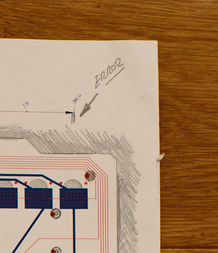
I need to correct some errors. The holes are only there to avoid routing copper through this area. The plan is to order the PCB without the holes. But we better do things right from the beginning. This needs to be corrected:
Photo 12-09-15 12 34 58.jpg
Photo 12-09-15 12 34 58.jpg (786.61 KiB) Viewed 5008 times
I hope to progress this during the weekend. Lets see if we have a full PCB by then.

User avatar
vivalarevolución
formerly prdlm2009

13 Sep 2015, 00:23

Great to see some progress. Not sure what you are thinking for the PCB fabricator, but I used PCBway for the XTant and I was happy with their pricing and quality.

User avatar
idollar
i$

13 Sep 2015, 13:40

vivalarevolución wrote: Great to see some progress. Not sure what you are thinking for the PCB fabricator, but I used PCBway for the XTant and I was happy with their pricing and quality.
Thanks for the tip. I will check it, for sure.

User avatar
shreebles
Finally 60%

21 Sep 2015, 10:54

Nice! This is the single most promising keyboard project that I know of. Having tried your F, I can only imagine how awesome this could be...

User avatar
Techno Trousers
100,000,000 actuations

18 Nov 2015, 23:26

We may get some more traffic in this thread, idollar, since I linked it in Ellipse's 4704 revival thread (which is nearing completion). Do you have any updates on this project for us?

User avatar
idollar
i$

23 Nov 2015, 15:06

jajaja

I have seen your post :-)

I am taking Friday off. I will try to finalise the prototype of the PCB. It will then be a matter of ordering it. I have all the parts at home.

User avatar
shreebles
Finally 60%

23 Nov 2015, 16:45

Wow! So you will build a complete, hopefully working prototype? Exciting!

User avatar
vsev

05 Dec 2015, 13:02

Nice to see this going further, I'm very interested in this project too !

Post Reply

Return to “Workshop”