Key Communications Keyboard Coating On Traces Coming Off Help
-
Fkazim
- Location: United Kingdom
- Main keyboard: Modded IBM Model F AT
- Main mouse: Mionix Naos 8200
- Favorite switch: Capacitive Buckling Springs
- DT Pro Member: -
- Contact:
Well before getting into any of that what pins do I solder to on the teensey++ for the rows and columns?
-
Anakey
- Location: UK
- Main keyboard: Planck
- Main mouse: Cyborg Rat 7
- Favorite switch: Alps skcm white
- DT Pro Member: -
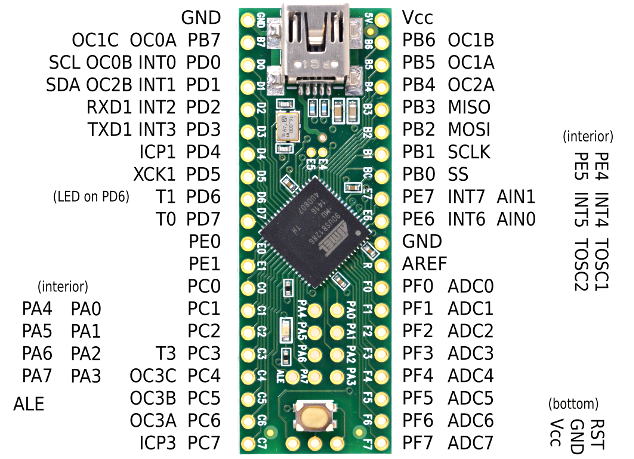
here is the pinout of the teensy2++
https://www.pjrc.com/teensy/pinout4a.png
you will want to keep pins D0 and D1 free if you are going to be using a screen as it will need those pins
As has been mentioned D6 does have an on board LED which can cause errors so best to avoid that pin other then that it is up to yu to decide where you are going to bve putting the rows/columns.
-
Fkazim
- Location: United Kingdom
- Main keyboard: Modded IBM Model F AT
- Main mouse: Mionix Naos 8200
- Favorite switch: Capacitive Buckling Springs
- DT Pro Member: -
- Contact:
OK Thanks for all the help last thing what pin on the teensey would I solder the keyboards caps lock LED to?
-
Fkazim
- Location: United Kingdom
- Main keyboard: Modded IBM Model F AT
- Main mouse: Mionix Naos 8200
- Favorite switch: Capacitive Buckling Springs
- DT Pro Member: -
- Contact:
OK when I setup the teensey do I just past in the code I got from the website for the basic layout and off I go? Will private message you tonight about the teensey is the teensey you are going to send me going to be setup already? or will I need to do that?
-
Anakey
- Location: UK
- Main keyboard: Planck
- Main mouse: Cyborg Rat 7
- Favorite switch: Alps skcm white
- DT Pro Member: -
the code you get from keyboardlayouteditor.com would need to be pasted into kbfirmware.com, you will need to set up your matrix, teensy pins, cps lock pin, keymap etc then further edit those files for your ctrl 1= F1 before compiling into a .hex file. Then you would need to flash that file to the teensy. It is not a simple process that is why its best to take the steps slowly rather then rush into it, make mistakes and then get frustrated when it does not work.
-
Fkazim
- Location: United Kingdom
- Main keyboard: Modded IBM Model F AT
- Main mouse: Mionix Naos 8200
- Favorite switch: Capacitive Buckling Springs
- DT Pro Member: -
- Contact:
When I made my layout in kbfirmware.com I checked the matrix It said my keyboard had. I noticed its slightly different from what I drew up which one is correct just wondering as it could be possible my matrix i drew is slightly inaccurate? But I'm not really sure Thanks for all the help it is so appreciated.
Below is the matrix it said I have let me know your thoughts.
Below is the matrix it said I have let me know your thoughts.
- Keyboard firmware.com matrix.PNG (26.23 KiB) Viewed 5019 times
-
Anakey
- Location: UK
- Main keyboard: Planck
- Main mouse: Cyborg Rat 7
- Favorite switch: Alps skcm white
- DT Pro Member: -
it will generate a matrix based on the layout, you would need to manually edit each switch to make sure it matched the matrix that you drew out. otherwise you would get errors like a f when should be a g etc
-
Fkazim
- Location: United Kingdom
- Main keyboard: Modded IBM Model F AT
- Main mouse: Mionix Naos 8200
- Favorite switch: Capacitive Buckling Springs
- DT Pro Member: -
- Contact:
OK will double check tonight just to be sure.
-
Fkazim
- Location: United Kingdom
- Main keyboard: Modded IBM Model F AT
- Main mouse: Mionix Naos 8200
- Favorite switch: Capacitive Buckling Springs
- DT Pro Member: -
- Contact:
Ok just confirmed the matrix for sure and neatened up some of the pin labels.
- 15696807160297773715817827558983.jpg (2.14 MiB) Viewed 4901 times
- 1569680908740565073324883877069.jpg (2.45 MiB) Viewed 4901 times
- 15696809988307815097786259397834.jpg (2.72 MiB) Viewed 4901 times
- 15696810261806200526286542731226.jpg (2.39 MiB) Viewed 4901 times
Last edited by Fkazim on 28 Sep 2019, 16:30, edited 1 time in total.
-
Muirium

- µ
- Location: Edinburgh, Scotland
- Main keyboard: HHKB Type-S with Bluetooth by Hasu
- Main mouse: Apple Magic Mouse
- Favorite switch: Gotta Try 'Em All
- DT Pro Member: µ
Here’s a good trick: use letters for the rows. So you don’t mix them up. Then you’ll know for sure where C4 is, etc. instead of potentially messing up 3x2 for 2x3.
-
Fkazim
- Location: United Kingdom
- Main keyboard: Modded IBM Model F AT
- Main mouse: Mionix Naos 8200
- Favorite switch: Capacitive Buckling Springs
- DT Pro Member: -
- Contact:
OK I appreciate the advice I will do that.
Thanks.
Thanks.
-
Fkazim
- Location: United Kingdom
- Main keyboard: Modded IBM Model F AT
- Main mouse: Mionix Naos 8200
- Favorite switch: Capacitive Buckling Springs
- DT Pro Member: -
- Contact:
Thought I would throw on the Tai-Hao keys as I am so close to converting this keyboard let me know what you think picture posted below also any ideas where I could source a big space bar in black to match the other keys?
Very high quality doubleshot ABS keycaps below is some close ups of the moulding.
- 15696778871804402551780644644254.jpg (2.44 MiB) Viewed 4928 times
- 15696792232122267264118738997297.jpg (2.33 MiB) Viewed 4903 times
-
Fkazim
- Location: United Kingdom
- Main keyboard: Modded IBM Model F AT
- Main mouse: Mionix Naos 8200
- Favorite switch: Capacitive Buckling Springs
- DT Pro Member: -
- Contact:
OK so update I tried to desolder those 2 chips for the columns and the coating over the traces started to come off. Not the actual traces the coating over them in fact after looking closer into it I can actually scratch the coating off with just my finger nail. So what do you guys recommend now Please help.
Thanks.
Also I got the Teensey Thanks a lot Anakey
Thanks.
Also I got the Teensey Thanks a lot Anakey
-
Fkazim
- Location: United Kingdom
- Main keyboard: Modded IBM Model F AT
- Main mouse: Mionix Naos 8200
- Favorite switch: Capacitive Buckling Springs
- DT Pro Member: -
- Contact:
Ok that's good news below is a picture of what I am taking about.
- Attachments
-
- 15702764086859205396257973252317.jpg (1.74 MiB) Viewed 4731 times
-
Fkazim
- Location: United Kingdom
- Main keyboard: Modded IBM Model F AT
- Main mouse: Mionix Naos 8200
- Favorite switch: Capacitive Buckling Springs
- DT Pro Member: -
- Contact:
I will try not to. As this coating came off whilst trying to desolder the chip. How should I go about removing the chips now. Or should I just solder directly to the chip and cut the power pins?
-
Anakey
- Location: UK
- Main keyboard: Planck
- Main mouse: Cyborg Rat 7
- Favorite switch: Alps skcm white
- DT Pro Member: -
you can still desolder the chips just do not take the coating off beyond that. Actually looking at it again all the traces going to the keyboard are on the opposite side so the traces you have shown will not be connected to the teensy anyway
-
Fkazim
- Location: United Kingdom
- Main keyboard: Modded IBM Model F AT
- Main mouse: Mionix Naos 8200
- Favorite switch: Capacitive Buckling Springs
- DT Pro Member: -
- Contact:
Well I tried desoldering again yesterday with my desoldering gun and same thing the thin coating on the traces just keeps scratching off. I have never seen this before with a keyboard PCB. I have only ever seen these thinly coated PCB's on one router that I repaired few years back. I really don't want to ruin the PCB. As you say though the traces for the matrix are on top of the PCB so should i just ruin those obsolete traces whilst trying to desolder the chip as I think that would be the only way anyways let me know your opinions.
Thanks.
Thanks.
-
Fkazim
- Location: United Kingdom
- Main keyboard: Modded IBM Model F AT
- Main mouse: Mionix Naos 8200
- Favorite switch: Capacitive Buckling Springs
- DT Pro Member: -
- Contact:
OK will do that.