Page 5 of 6
Posted: 03 Apr 2018, 23:49
by BlindAssassin111
scottc wrote: ↑I figured as much, thank you for investigating though!
If you are interested and you think there might be 9 others interested, I could design a PCB to work with the AT101, AT101W, SGI Granite, or any bigfoot. I could easily do this, just need to know if the cases are different between them and if there is anything like locating posts, or something else that may need to be accounted for.
Pricing would be similar to the omnikey ones, as the board wouldn't be as long, but needs to be taller to fit the controller.
Posted: 04 Apr 2018, 00:00
by BlindAssassin111
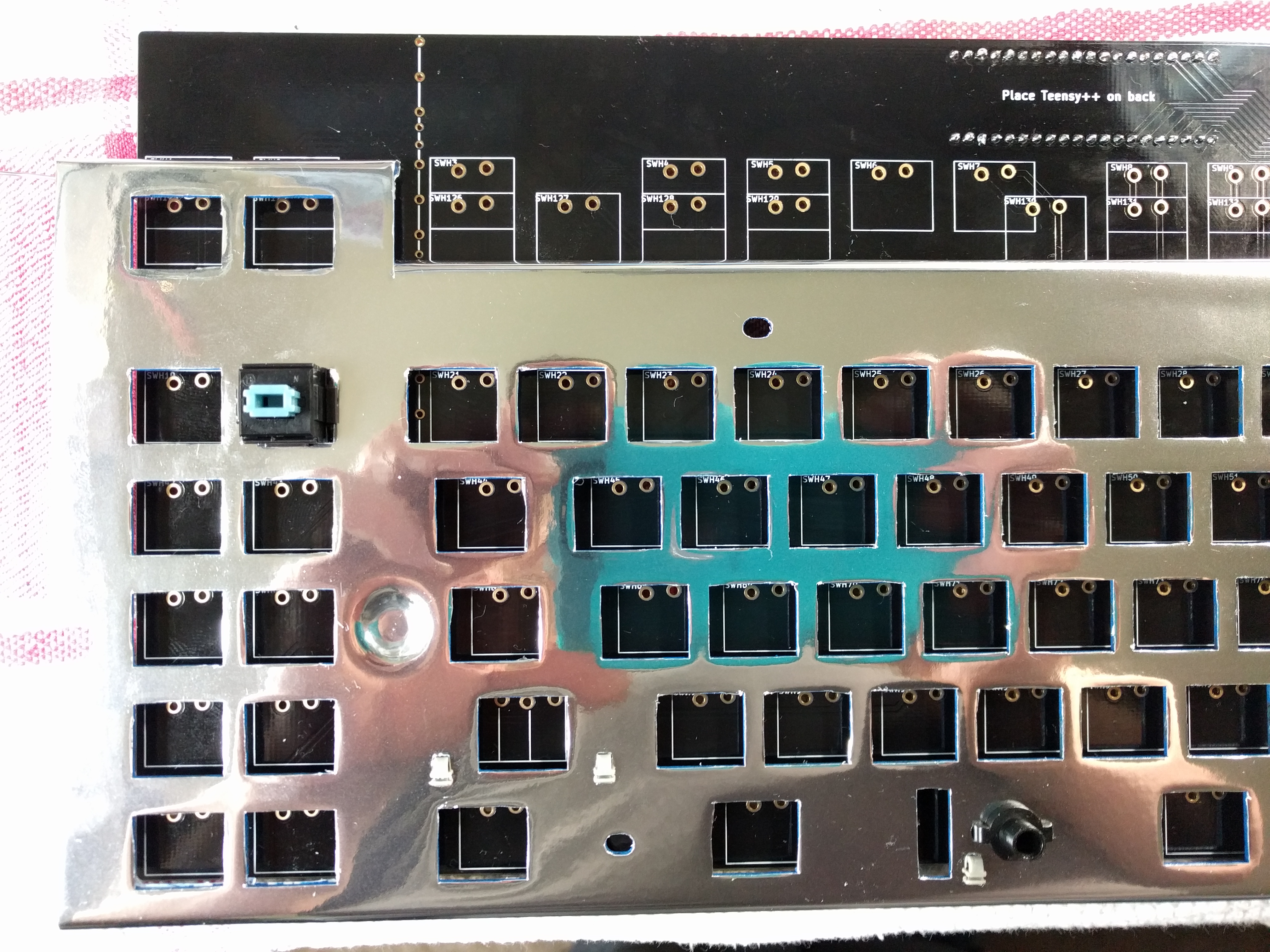
Here is the video of the PCB working.
https://youtu.be/7isvHLAJiGw
Posted: 04 Apr 2018, 03:36
by //gainsborough
That PCB looks awesome, dude! Thanks again for all the work you put into this!
What did you "plug" your teensy into? I've never seen it so raised off the PCB like that - it looks awesome. Although, I have to admit that I've also never owned a teensy before...
Posted: 04 Apr 2018, 03:50
by BlindAssassin111
//gainsborough wrote: ↑That PCB looks awesome, dude! Thanks again for all the work you put into this!
What did you "plug" your teensy into? I've never seen it so raised off the PCB like that - it looks awesome. Although, I have to admit that I've also never owned a teensy before...
I just used female headers so I can move the Teensy around if need be, which is a good idea.
Posted: 05 Apr 2018, 04:52
by BlindAssassin111
Update:
I have to redo the firmware as the logic for the LEDs was backwards, was lazy and used kbfirmware, so I have to setup the firmware for everyone and this may take a bit, and I want to test to make sure it works before sending the boards out as I haven't been able to test LED functionality yet.
Posted: 05 Apr 2018, 22:38
by BlindAssassin111
Update:
Okay just finished the default firmware, with a bit of help from TerryMathews to figure out the LED issues I was having(all code based issues). Everything works now and is fully tested, Sadly in the process I had to kill the board with the gouge on it as it was also shorting the led positive to ground so it would be an ugly fix to remake the not destroyed traces, so only 5 boards are available as I destroyed a personal board I need to replace. So I will start packaging and preparing for shipment tomorrow, and will start shipping these out this weekend and the beginning of next week.
Will be merging my QMK fork soonish, so it will be supported there. Just have to makes sure everything is good before I do so.
Posted: 07 Apr 2018, 06:42
by BlindAssassin111
Started packaging, but realized I needed a few more things before I can finish, so will get those this weekend.
Also wanted to point out that all of the soldered mounting holes on the PCB are off...so if you use them, please place a few switches around the board(including numpad enter as it will help see if the board is offset) and then mark the holes to be filed to fit. This way you don't have switches slanted on the plate and I guarantee it is safe to file those holes as long as you stay within the exposed gold pad, which is easy as no hole requires that much filing. I wish they weren't this far off, but once again me and polecat were not using the most accurate method to determine the mounting pad locations and it shows. Will try and correct that in the file so if I make another batch they fit better.
Everything else on the board is perfect though, LEDs fit better than original as I have correct spacing unlike Northgate themselves. And if you are debating about what resistance to use for the LEDs, 330 ohm worked well with the following LEDs, which gave almost original brightness.
https://www.mouser.com/ProductDetail/Ki ... Bqog%3d%3d Also they are the same exact size as the originals and look basically the same, which is a nice touch imo.
Posted: 08 Apr 2018, 22:39
by BlindAssassin111
Finished building my omnikey with the PCB, which took way longer than I had expected...But really happy with the results. Everything works as I expect and programming was actually easier once the whole LED problem was solved(polarity logic in code was flipped). Also did a few fixes to the QMK firmware, fixed the bottom row mapping and forced NKRO as it wasn't enabled, so now everything should be ready for everyone to modify.
Will begin shipping out boards tomorrow, but international orders may ship out a tad later, just depends when I get the labels made.
Posted: 09 Apr 2018, 00:26
by //gainsborough
BlindAssassin111 wrote: ↑Started packaging, but realized I needed a few more things before I can finish, so will get those this weekend.
Also wanted to point out that all of the soldered mounting holes on the PCB are off...so if you use them, please place a few switches around the board(including numpad enter as it will help see if the board is offset) and then mark the holes to be filed to fit. This way you don't have switches slanted on the plate and I guarantee it is safe to file those holes as long as you stay within the exposed gold pad, which is easy as no hole requires that much filing. I wish they weren't this far off, but once again me and polecat were not using the most accurate method to determine the mounting pad locations and it shows. Will try and correct that in the file so if I make another batch they fit better.
By mounting hole do you mean the holes that you use to screw in the PCB with the bottom panel or the holes that secure the PCB to the mounting plate?
Posted: 09 Apr 2018, 00:27
by //gainsborough
BlindAssassin111 wrote: ↑Finished building my omnikey with the PCB, which took way longer than I had expected...But really happy with the results. Everything works as I expect and programming was actually easier once the whole LED problem was solved(polarity logic in code was flipped). Also did a few fixes to the QMK firmware, fixed the bottom row mapping and forced NKRO as it wasn't enabled, so now everything should be ready for everyone to modify.
Will begin shipping out boards tomorrow, but international orders may ship out a tad later, just depends when I get the labels made.
Also: pic!! =)
Posted: 09 Apr 2018, 00:36
by BlindAssassin111
//gainsborough wrote: ↑
By mounting hole do you mean the holes that you use to screw in the PCB with the bottom panel or the holes that secure the PCB to the mounting plate?
I mean the ones that attach the PCB to the switch plate. All are off just enough that with switches installed after, they won't sit properly, so switches have to be mounted partially before the board can be filed and screwed in.
Pic incoming hold on.
- 20180408_173638.jpg (1.35 MiB) Viewed 9073 times
Proof the PCB is in there, and converting to ANSI so non matching enter and the slash key is missing atm:
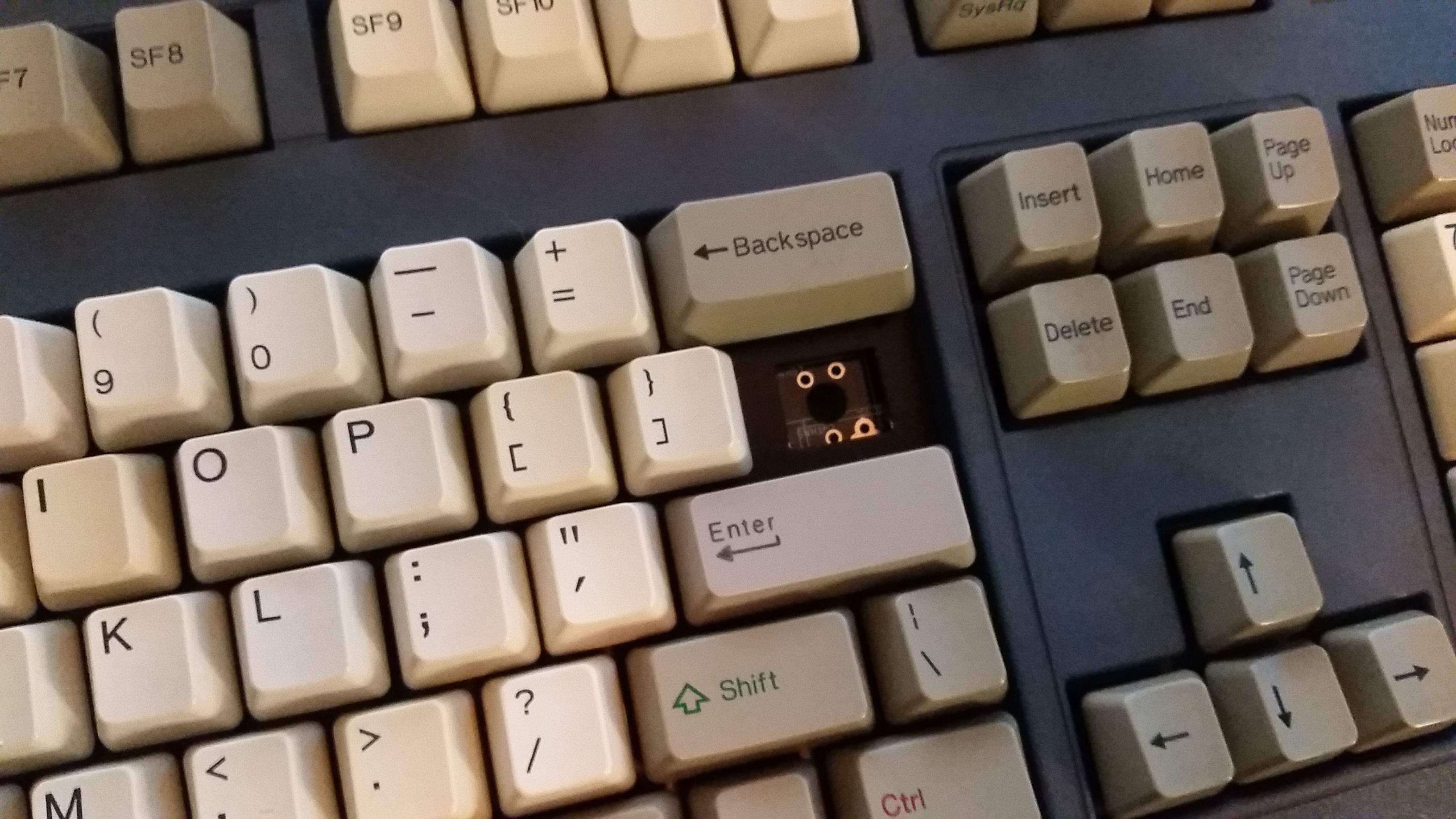
- 20180408_173652.jpg (1.49 MiB) Viewed 9073 times

- 20180408_173659.jpg (1.6 MiB) Viewed 9073 times
Posted: 09 Apr 2018, 01:54
by //gainsborough
DAMN! That is gorgeous!!! What color paint is that?! I want to use it for an omnikey 101 i'm working on as well! Why didn't you solder in a pipe key switch? ALso what switches did you use?
As for the mounting holes, there would be no problem forgoing all of them, right? The switches soldered to the PCB should be rigid enough I would imagine.
Posted: 09 Apr 2018, 02:13
by BlindAssassin111
//gainsborough wrote: ↑DAMN! That is gorgeous!!! What color paint is that?! I want to use it for an omnikey 101 i'm working on as well! Why didn't you solder in a pipe key switch? ALso what switches did you use?
As for the mounting holes, there would be no problem forgoing all of them, right? The switches soldered to the PCB should be rigid enough I would imagine.
The paint is the Dupli-Color Vinyl and fabric paint from O'reillys. It is more like a spray dye than paint, so the texture on the board is still perfect like it came, and doesn't flake at all. Love the color.
Didn't solder it as I wasn't sure if I wanted to convert to ANSI yet, and only decided after putting the board together, to do just that. So I will be soldering it in at some point soon. I used SKCM whites as it was the only alps I have and the exact ones that came with the board.
I would recommend using the screws still, adds strength to the board and that little bit extra is nice because of how omnikeys mount the plate to the case on the "newer" ones, so they flex a bit when you type. Optional but not more than 5 minutes to modify the holes.
Posted: 09 Apr 2018, 02:18
by //gainsborough
what did you use to file the holes - I've never done a mod like that. Thanks for paint details!
Posted: 09 Apr 2018, 02:23
by BlindAssassin111
//gainsborough wrote: ↑what did you use to file the holes - I've never done a mod like that. Thanks for paint details!
Cheap small files from home depot(or maybe harbor freight, don't remember), cost like $5. Just get the small ones and use the circle file to open the holes. Not much effort required, the files eat the FR4 PCB material easily so even a few strokes and you are almost done.
Kinda like this set, don't have to be good quality as you don't need them to last forever.
https://www.harborfreight.com/12-piece- ... -4614.html
Posted: 10 Apr 2018, 01:49
by BlindAssassin111
All US orders have been shipped out, will try and do the international ones tomorrow or wednesday.
Posted: 10 Apr 2018, 20:12
by Engicoder
Great! Thanks for all your work to make this happen.
Posted: 11 Apr 2018, 03:01
by BlindAssassin111
Sent an email to all international orders, need a phone number in order to make the shipping labels, didn't know that until now. So please respond to the email with that info. ASAP so I can get your orders out.
Posted: 12 Apr 2018, 19:43
by BlindAssassin111
Okay, sent out all international orders. Should have received an email yesterday.
If you contacted me about shipping later, don't worry your boards are still here and will ship later.
For those that already received theirs, I know there are a few, please post pictures of the builds when you finish. I want to see what you do with them and the awesome projects that come out of this.
Posted: 14 Apr 2018, 08:12
by Hak Foo
Any chance you've got a firmware image we can flash for testing?
I got mine yesterday and am at the halfway mark- the diodes, LEDs, and Teensy are installed, but once you start soldering switches, it becomes difficult to unwind things if you had a cold joint or bad diode. I figure if I can test it like the video, I can confirm it's sound before I start installing switches.
Posted: 14 Apr 2018, 17:09
by BlindAssassin111
Hak Foo wrote: ↑Any chance you've got a firmware image we can flash for testing?
I got mine yesterday and am at the halfway mark- the diodes, LEDs, and Teensy are installed, but once you start soldering switches, it becomes difficult to unwind things if you had a cold joint or bad diode. I figure if I can test it like the video, I can confirm it's sound before I start installing switches.
Sorry forgot to send out the updated one:
Here is the current default hex:
https://drive.google.com/file/d/1Ug1du9 ... sp=sharing
if you press the slash key(mapped as momentary layer) and the tilde, it is the reset. The 1U keys on the bottom row are mapped as windows keys atm, and everything else is normal.
Posted: 11 May 2018, 18:16
by just_add_coffee
Am I not understanding something, or are the left side function keys about ~5mm left-of-center (or everything else is ~5mm right-of-center)?
- IMG_20180510_152533.jpg (3.26 MiB) Viewed 8874 times
I can line up either the function keys or everything else, but not both.
Anyone else having this issue?
Aside from that, this is one pretty PCB!
Posted: 11 May 2018, 18:56
by mike52787
just_add_coffee wrote: ↑Am I not understanding something, or are the left side function keys about ~5mm left-of-center (or everything else is ~5mm right-of-center)?
IMG_20180510_152533.jpg
I can line up either the function keys or everything else, but not both.
Anyone else having this issue?
Aside from that, this is one pretty PCB!
worst case scenario it looks like you could remove the left hand f row cluser, remove some of the pcb material, and run jumper wires over to the main pcb. seems like the measurements were done wrong or something.
EDIT: just to clarify, I mean remove some material from the left hand f key block, my wording was a bit confusing.
Posted: 11 May 2018, 19:12
by just_add_coffee
mike52787 wrote: ↑
worst case scenario it looks like you could remove the left hand f row cluser, remove some of the pcb material, and run jumper wires over to the main pcb. seems like the measurements were done wrong or something.
EDIT: just to clarify, I mean remove some material from the left hand f key block, my wording was a bit confusing.
Nah, your wording was fine to me. I understood. I was hoping for
different wording though.

But on the bright side, I've never cut a PCB before, so I'll get to do something new. Thanks Mike!
Posted: 11 May 2018, 19:15
by mike52787
just_add_coffee wrote: ↑mike52787 wrote: ↑
worst case scenario it looks like you could remove the left hand f row cluser, remove some of the pcb material, and run jumper wires over to the main pcb. seems like the measurements were done wrong or something.
EDIT: just to clarify, I mean remove some material from the left hand f key block, my wording was a bit confusing.
Nah, your wording was fine to me. I understood. I was hoping for
different wording though.
But on the bright side, I've never cut a PCB before, so I'll get to do something new. Thanks Mike!
please wear a respriator/mask, fiberglass dust is quite harmful to inhale.
Posted: 11 May 2018, 19:17
by just_add_coffee
mike52787 wrote: ↑
please wear a respriator/mask, fiberglass dust is quite harmful to inhale.
Thank you for telling me. Because I would not have thought of that.
Edit: And I did not know what PCBs were made of either. Learning all sorts of new things today!
Posted: 11 May 2018, 19:17
by martink
just_add_coffee wrote: ↑
Anyone else having this issue?
Someone on geekhack has reported the same problem.
Posted: 11 May 2018, 19:36
by just_add_coffee
martink wrote: ↑just_add_coffee wrote: ↑
Anyone else having this issue?
Someone on geekhack has reported the same problem.
Thanks. Found the thread ...
https://geekhack.org/index.php?topic=94 ... msg2597486
Posted: 12 May 2018, 05:31
by BlindAssassin111
I will reply here so people in the future can see this.
I was unaware of the different block spacing among certain models(so far the Ultra and gold label 102's are the only documented issues) which is unfortunate, the boards line up perfectly with the Ultra T and boards that don't have the connector daughter board in the case(according to the guy over on GH, haven't confirmed personally), which may affect quite a bit more boards sadly...
I recently purchased an older 102 for a whopping $61(I was very lucky on this one), hopefully this board has the issue so I can measure for myself rather than relying on others(guy on GH has been helpful but not having a response the instant I have a question slows the process down significantly, so I spent money) and will begin looking at making a new revision of the board. I am going to fix this by adding more switches on the board that are offset(which adds quite a bit of complexity) or I may need a new version for certain "generations" of the omnikeys.
If you have had this problem please post pictures. I will try and work with you on getting this issue resolved, which will happen in a round 2 GB as I can't order just 2 boards for those who have reported problems(at least so far).
Posted: 12 May 2018, 07:27
by //gainsborough
Oh dang, that’s disappointing! This summer I was planning on putting it together for my gold label. I’ll be sure to post pics if/when I run into trouble.