(Model MF) Remodeling the Model M (aka.. the Mara)

User avatar
lot_lizard

09 Jun 2016, 20:43

So I thought about this quite a bit last night, and I think the most ideal solution of eliminating the spring's reverbation when returning to it's ideal state (the key-up issue), is reducing the contact surface... like we have already mentioned. But since this is a moving part whose movement varies quite a bit, the contacting surface needs to be wide enough to account for the spring being erratic.

Lets assume the spring returns on the "y-plane", we need to account for movement as well on the "x-plane" when it slaps the surface (doesn't always hit the same spot). Given that, two crossed cylinders really is the best approach. According to Hertz, this is the equivalent of a sphere striking a plane (certainly more ideal). It will eliminate a huge amount. Enough?!?... No idea, but certainly better :)
Image

So I have thrown this together (notice the "bump" in the stem)
keystemSilencerBottom.png
keystemSilencerBottom.png (135.09 KiB) Viewed 4282 times
And a cross section to aid in seeing the difference
keystemSilencerCrossSection.png
keystemSilencerCrossSection.png (104.4 KiB) Viewed 4282 times

User avatar
DMA

09 Jun 2016, 20:55

Hmm. I wonder if it grabs the spring if that hits the bump just right. But it should work, indeed.

I have some unicomp keys laying around - will actually try to make the hole higher on the, for the lack of better word, distal side of the keystem. Want to see what happens. Will the spring jumps out of the socket? Eventually it should, but at what height? FOR !!SCIENCE!!

User avatar
lot_lizard

09 Jun 2016, 21:30

DMA wrote: I have some unicomp keys laying around - will actually try to make the hole higher on the, for the lack of better word, distal side of the keystem. Want to see what happens. Will the spring jumps out of the socket?
I actually tried that with one of my stem prints (I have had maybe 10 total variations thus far trying crazy ideas). The pressure needs to be maintained or the spring gets "sloppy". Without enough pressure, it still works, but becomes a clanky mess. I would have to go back and look, but I believe this was only a .5-1mm release in the spring compression before it became chaotic.

EDIT: But there is zero reason not to try yourself. You might experience different results. Just a suggestion is keep the changes TINY with each attempt

Also for the sake of eliminating additional issues, we could certainly apply the same contact mechanics to the flipper top
flipperSilence.png
flipperSilence.png (22.64 KiB) Viewed 4270 times
You really can't do much about the flipper paddle bottom itself unless you improved the conduction properties of the material. Then it could also be reduced. But we have to keep in mind that changing the weights, dimensions, etc. of the functional surfaces is going to change the experience. The beauty about these other improvements, they are eliminating nuisances without effecting performance (or at least very little)

User avatar
lot_lizard

09 Jun 2016, 21:47

I should have mentioned this long ago, and I think it will actually surprise most.

The event that actually causes the spring to "buckle" is not only the shear pressure that continual builds, but it's actually the stem itself pushing the flipper downward that causes to the spring finally reach maximum shear pressure. Until that point, the spring is held in alignment by one peg on each end being on the same plane... or close to (the keystem spring "nipple", and the flipper "stem". Once the key stem comes into contact with the flipper, it rotates the flipper forward very slightly, but enough to cause maximum shear stress on the spring since the vertical plane is now broken further. Then the spring does the rest by buckling, further rotating the flipper paddle downward.

It is an amazing little dance the two perform together. I think you might be able to see it in the gif animation that was posted earlier, but you would likely need to go frame by frame. It's very subtle, but the keystem contact is the trigger. It's the real reason the keystroke is always so consistent (stems are all the same length). If the spring was the trigger, keys would be very erratic compared to each other

EDIT: Added the image again the infodroid originally posted (thanks for doing that) to save a search
Image
Last edited by lot_lizard on 09 Jun 2016, 21:58, edited 1 time in total.

User avatar
DMA

09 Jun 2016, 21:56

lot_lizard wrote: EDIT: But there is zero reason not to try yourself. You might experience different results. Just a suggestion is keep the changes TINY with each attempt
Hehe. I know a bit about subtractive changes - anyone cutting wires knows that you can't make wire longer :)
But thanks for the warning, it should be there for the general public.
lot_lizard wrote: You really can't do much about the flipper paddle bottom itself unless you improved the conduction properties of the material.
Electroplating! (With gold, of course. Why settle for less?)

Update: oh wow, never noticed that the process is triggered by the stem. It is obvious in retrospect though - relying just on the spring will not produce any consistent results. I think exact moment of buckling will depend even on ambient temperature, let alone vibration from the adjacent keys.

We need a page on with with this gif much larger and slower. And with arrows pointing to the places of interest.
There bound to be a video of it somewhere on youtube.

User avatar
lot_lizard

09 Jun 2016, 23:24

DMA wrote: Update: oh wow, never noticed that the process is triggered by the stem. It is obvious in retrospect though - relying just on the spring will not produce any consistent results. I think exact moment of buckling will depend even on ambient temperature, let alone vibration from the adjacent keys.

We need a page on with with this gif much larger and slower. And with arrows pointing to the places of interest.
There bound to be a video of it somewhere on youtube.
That's a good idea if someone wanted to take that on. You would loose definition, but certainly easier to make out. I am going to take a few days off (death in the family) but wanted to kick out something I would like feedback on (like, hate, alternatives, whatever...). My skin is thick... The more feedback the better.

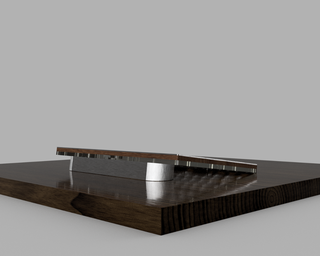
I have been thinking about this future flat board for a while now (using the Cherry mounts), and assuming we can compress the PCB considerably around the edges, and have a smaller controller... I think I can pull off a floating case stand. Something that still honors the pitch and height of the M (short for Mecca), but from almost any angle would appear that the board and minimal housing is " floating". The challenge was to make that stabile, but I think I have figured that out. Let me know others thoughts, but the idea is a "case-less case off the table slightly". Attaching a couple of images of other things leveraging cantilevered designs to wet your whistle. At minimum, it's what I want for myself (someday when I finally post some images of my work desk, you'll see why). If we could ever really slam Bluetooth into this... My dream would be complete.

If we like it, I'll work up some renders next week when I return from bereavement
image.jpeg
image.jpeg (138.05 KiB) Viewed 4229 times
image.jpeg
image.jpeg (38.03 KiB) Viewed 4229 times
EDIT: MrBishop had a thread going in the last couple of days that made me think we should probably kick off discussions about it. This is an image of his work (which is excellent), but I would like to hide the base a bit better from all angles, and we have the opportunity to lift the front off the table slightly and still remain consistent with the M. I think personally think it will be glorious, but again, welcome thoughts
Image

User avatar
DMA

10 Jun 2016, 03:04

Condolences. Don't know what else to say. Been there.

Hey, that's Apple BT keyboard on the attachment! BS will be much higher.

Compressing PCB on the sides will require something pervertedinventive - like branching out the sense part to the coprocessor to which the main part of the controller will talk via some serial bus and putting that somewhere between enter and del key.
Which kind of rules out HHKB-style layouts - because it has to be on the top side of the PCB (don't think one can drive 'em from the top, though this worth testing), must have enough space for the sense traces and bypass capacitor(s) around it.

Link to the main controller and power can be brought from the lower layer - but that would mean vias. Don't know squat about PCB production, but it seem to make PCB more complex, hence more expensive.

BT would make lots of sense for this one - it will probably weigh less than 4 pounds. But the power drain of this two-chip system will mean battery life of like 5 minutes :)
Although it needs to have some sort of leg along the back of it to provide some incline. This can be used for batteries.

Update: BUT!
Using interlaced scan it may just be possible to bring the sense lines to the controller using the other side of the board - i.e. vias. Signal will probably be quite weak because TONS of parasitic capacitance, I'm afraid.

But. It is a Worthy Challenge.
For phase 2.

Hey, any actual electronic engineers around there? Or at least people knowing a way around PSPICE?
I can write firmware (it seems), but if I'll be designing this I'll spend all my breakfast money on the 50 PCB prototypes it will take me to approach something remotely reproducible. Etching the first 40 at home will probably be a bit cheaper (single key prototypes are out of the question, so lots of laminate), but my rental apartment manager will go nuts if he finds out I have copper salts, hydrochloric acid, peroxide _and_ a small child in close proximity of each other on his property.

User avatar
pyrelink

10 Jun 2016, 03:06

I am sorry for your loss lizard. Really sucks.

==

I like the idea of the case a lot. Looks like a very elegant case. The board itself is still going to be relatively think as it can only be as thin as the barrels are, but I think it could be an elegant design. Like Muirium and I were talking about years ago, the base stand could be used to house the controller and the large rechargeable battery that will of course power the keyboard for bluetooth. Which I would usually call wishful thinking but this thread has been full of nothing but surprises.

Alternatively if everything fit into the main keyboard, I would like to see the incline base detachable possibly with magnets, for those people who don't want an incline on their keyboard.

EDIT: I basically just echoed what DMA said, but to reply, I don't know how lot_lizard plans to integrate the controllers, but as it is with the current FSSK and FEXT boards, they currently require you to solder onto the board, an external xWhatsit board, so the separated controller, from the main PCB *shouldn't* be an issue?

EDIT 2: ahh forgot about the bluetooth part of the controller, which yeah would be a more complicated PCB and actually quite a bit of effort. I wonder how friendly xwhatsits controller is to power draw over bt?

User avatar
lot_lizard

10 Jun 2016, 03:49

You'd be surprised the volumes I could add elangantly under the PCB in a floating frame (even current setup with zero compression, though I would like to drain the turnip)... I love this though. Keep it up. This is all phase 2... Pipe dream shit. 20% will stick. What I love about this exercise is, the world contributes in an international think tank. More the merrier, and remember "no bad ideas"... It inspires better thoughts even if it doesn't work out. Should I include GH? I have avoided until now with intent.

Also, appreciate the thoughts about "life". We've all been there in some capacity (some worse than others, but the same end result)

User avatar
Techno Trousers
100,000,000 actuations

10 Jun 2016, 05:00

I'm sorry for your loss as well, lizard.

That GIF of the spring action gave me an idea... Since you're dreaming of an art piece, how cool would it look with transparent barrels and gold or stainless steel springs? Could you even make transparent barrels that had the same properties as the original F ones?

User avatar
DMA

10 Jun 2016, 05:37

Techno Trousers wrote: I'm sorry for your loss as well, lizard.

That GIF of the spring action gave me an idea... Since you're dreaming of an art piece, how cool would it look with transparent barrels and gold or stainless steel springs? Could you even make transparent barrels that had the same properties as the original F ones?
..and keycaps!
There's no transparent steel though, so PCB and controller don't have to be.

User avatar
pyrelink

10 Jun 2016, 18:58

We could always try using transparent aluminum!

andrewjoy

11 Jun 2016, 10:07

pyrelink wrote: We could always try using transparent aluminum!

that kind of exists

https://www.youtube.com/watch?v=Ye2c0nWxksA

User avatar
Techno Trousers
100,000,000 actuations

11 Jun 2016, 14:53

Ha ha. Try poking that with your finger, or whacking it with a spring, though!

User avatar
DMA

12 Jun 2016, 06:57

andrewjoy wrote:
pyrelink wrote: We could always try using transparent aluminum!

that kind of exists

https://www.youtube.com/watch?v=Ye2c0nWxksA
That's aluminum oxide.

Sapphire plates will be a bit expensive, methinks. Quite scratch-resistant though.

User avatar
lot_lizard

13 Jun 2016, 04:02

These are really interesting ideas. Especially the transparent barrels (or at minimum colored ABS), and clear/colored keystem inside the barrel. I will have to look into the properties of clear plastics. I don't know much about them, other than they are more brittle (which typically relates to a more scratch resistant surface, which is very desirable). The springs would end up being stainless steel anyway, so that is a bonus. Brass and piano wire are the other other real viable options, and there are disadvantages to each.

User avatar
lot_lizard

14 Jun 2016, 00:42

Two modifications have been made to the barrel. The front slot has been thickened to its max (wanting to try thicker plastic before we try multi-materials due to the expense). This improvement should lessen the sound of the spring striking the the front of the barrel when the spring buckles. The second is what I suggested earlier for limiting the sound of the flipper slapping the barrel on key release, but instead of altering the flipper, I think it makes more sense to add the sphere to the barrel ceiling.
The front slot is now filled in
barrelSilenced.png (10.76 KiB) Viewed 4050 times
Sphere bumper added of the barrel ceiling (view from the bottom)
barrelSilencedBottom.png (14.49 KiB) Viewed 4050 times
EDIT: I increased the size of the sphere slightly in the version that was sent off for printing
Last edited by lot_lizard on 14 Jun 2016, 19:48, edited 1 time in total.

User avatar
lot_lizard

14 Jun 2016, 16:08

One additional silencing improvement, and I think we have covered everything mentioned thus far. I have added support to the keystem to hold a dampening o-ring (much like the Cherry o-rings). The one significant advantage of ours over theirs though... the keystem has been altered so THERE IS NO LOSS OF KEY TRAVEL :). We had room to grow the adapter vertically without impacting the height of the actual key profile (which I had planned on doing anyway to make the cap more secure). Based on how molds work, there are possible tweaks we might need to make to the design (keep cost down), but they wouldn't have functional impact on our goal. If anyone is having difficulty making out what the improvement is, let me know, and I can add a mock o-ring around the stem to help the visualization.
keystemSilencerORing.png
keystemSilencerORing.png (17.57 KiB) Viewed 4026 times
Also an update, I stopped by the machine shop yesterday to look at their test run on stock metal for our metal bends and breaks to the top and bottom plates. They looked perfect. They should be able to knock out our actual prototype plates by the middle of next week.

User avatar
lot_lizard

15 Jun 2016, 02:28

Rough estimates on pricing for the standard versus "silent" (Type-S) differences in material costs looks to be around 11 cents USD a key. With 85+% of that being the cost of the silicon o-ring. I am assuming this is worth further development, but wanted to check the opinion of others. Regardless, I would be doing a prototype for myself, but in the end... we would likely only offer one version of the board for phase 2 given mold pricing. So the additional cost of a quieter version would be approx. $10 USD for the SSK, and $12 USD for the 101-key.

I have ordered prints for the quieter versions (staged so I can test the incremental improvements of each mod), but again... I'm not sure the price point where others would have interest. I would be very happy with the original F sound myself, but if improvements can be made without altering the feel... I would think it is worth it?!?

Also, for phase 2, we will have the opportunity to "improve" key layout of the function row if we choose. Would be like to see the F-row brought down closer to the rest of the keys? As tight as possible, slightly gapped, original... Looking for dialogue. I dont hit them much, but appreciate them being there when I do need them

EDIT: I did validate, and we are able to compress the key rows .45mm without having to alter the barrel or flipper designs (what is needed for the flat board). It is looking very promising. If we can get the PCB and controllers compacted sooner rather than later, I think we can turn around a design for phase 2 within a couple of months

User avatar
DMA

15 Jun 2016, 08:23

lot_lizard wrote: we would likely only offer one version of the board for phase 2 given mold pricing. So the additional cost of a quieter version would be approx. $10 USD for the SSK, and $12 USD for the 101-key.
$12 over $200 is one thing, $12 over $100 is a completely different one. Another question is "will there be different keystems for the different rows?" Because if stems are different - wouldn't it mean 5 different molds hence 5x tooling costs?

Another possibility is to just publish the models and let people who want silenced versions print them. Doable unless you want custom O-rings, IMO. Don't know how much it will cost though. $50? $100?

Yet another possibility is separate group buy if enough takers. If the new keystems are compatible with model M - that will definitely expand the audience.

I want to reiterate that "without altering the feel" is the key (pardon the pun). Can't improve on that - in no small part because there will be fight to the death about the definition of "improve" :)
lot_lizard wrote: I did validate, and we are able to compress the key rows .45mm without having to alter the barrel or flipper designs (what is needed for the flat board). It is looking very promising.
Not sure about going that way.. ISO postulates 19mm (and barrels seem to be 19mm wide), but ergonomic studies tell us that 18mm horizontal pitch is better somewhat, though not significantly better. 16mm would be pushing it though - people with large hands will suffer.
Reducing vertical spacing looks safe though (also with the flat plate the vertical key gaps will be wider - barrel base I have on my table is 19x21mm - so more than one reason to do that).

User avatar
chzel

15 Jun 2016, 09:04

DMA, the barrel distance is not 19mm on the M, they are further apart because of the curved plate. As the barrels extend "upward" the get closer together and end up ~19mm apart. So going to a flat plate you need to close that extra gap.

User avatar
tentator

15 Jun 2016, 09:53

I'd definitely want modified barrels and flippers that would dampen the sound and ring but preserve the feel!! Also consider that higher pitches are more annoying than lower ones. That's most probably many like model f to m (bigger flipper gives a lower response) and thick pbt... the famous "thock" instead of the annoying "click" basically :))

User avatar
lot_lizard

15 Jun 2016, 09:57

Sorry for the length. This is just a complex topic, and it is difficult to do without girth. Also... just for clarity to everyone because I am not calling this out the best on these posts. Everything being discussed here is for PHASE 2 (new board), with a current desired to test a flat approach to the plates with Cherry adapters in a brand new case. This might all fall flat on its face, but I am going to try because all of my testing is showing that this would work. PHASE 1 is still the drop-in replacement as true to factory as possible.

I realize you were both aware of that, but wanted to call out for others.
chzel wrote: DMA, the barrel distance is not 19mm on the M, they are further apart because of the curved plate. As the barrels extend "upward" the get closer together and end up ~19mm apart. So going to a flat plate you need to close that extra gap.
Exactly... The compression was in regards to the spacing between the key ROWS (should have called out better previously). When we flatten the board, the spacing between the rows t the point of key cap surface is widened because we are no longer sitting inside an arced plane. So to return back to the original key spacing, the barrels have to be tightened vertically by 1.45mm (EDIT: originally stated .45mm). I thought we might have to alter the barrel designs from original to allow for the tighter spacing, but this turned out not to be the case (which is good)
Flat top plate after 1.45mm (EDIT: originally stated .45mm) row compression. It's tight, but very manageable for barrel installation. Also, you see how much the F-row could be brought down if we had the desire
topPlateRowSpacing.png (1.73 KiB) Viewed 3931 times
DMA wrote:
lot_lizard wrote: we would likely only offer one version of the board for phase 2 given mold pricing. So the additional cost of a quieter version would be approx. $10 USD for the SSK, and $12 USD for the 101-key.
$12 over $200 is one thing, $12 over $100 is a completely different one. Another question is "will there be different keystems for the different rows?" Because if stems are different - wouldn't it mean 5 different molds hence 5x tooling costs?

Another possibility is to just publish the models and let people who want silenced versions print them. Doable unless you want custom O-rings, IMO. Don't know how much it will cost though. $50? $100?

Yet another possibility is separate group buy if enough takers. If the new keystems are compatible with model M - that will definitely expand the audience.

I want to reiterate that "without altering the feel" is the key (pardon the pun). Can't improve on that - in no small part because there will be fight to the death about the definition of "improve" :)
Completely agree with all of that... And this is probably a little early yet for me to have even asked this until we see (including me) a working model. I do think we will have noticeable audible improvement, and am expecting close to zero difference in actual feel. For the number of molds (think parts, not physical molds), we would need the following for both a standard and "silenced" version. Those with a preceding asterisk would be candidates for printing because of lower volumes
  • Standard F barrel (currently slated to be a peg lock)
  • Type-S standard barrel
  • * Spacebar stabilizer barrel
  • * Type-S spacebar stabilizer barrel
  • * Vertical stabilizer barrel (Enter and + for the 10-key)
  • * Type-S vertical stabilizer barrel
  • Flipper
  • * Phase 1 Plate spacer (I will test with and without to see if there is even any improvement). Phase 2 would be a completely different design
  • Standard Cherry keystem (likey Type-S only)
  • * Spacebar Cherry keystem (again Type-S)
If we can refactor the barrel placement slightly for the special keys, they would be able to use the universal Cherry stem as well (which has huge cost impact). So from the above, we would have 4 parts that HAVE to be injection molded to keep costs down (ideally more). The way molds work, you can have multiple parts in a single mold. These could be either redundant parts, or unique parts. There is a balance that will be performed to get those ratios just right, and is directly tied to the size of the press, material used, and the volume of parts in the run. Each additional part adds cost to tooling, but it really isn't horrid. Example, if you are producing two similar but unique parts, the cost of the tooling is much less than double the cost (think only 10-20% increase per part) if you are able keep the some number of physical molds.

Again... it was probably premature to ask about the cost increase earlier until we know more. Still a good deal of research ahead (both of functionality and actual cost). But I would assume it is in the neighborhood of 11-13 cents a key over the cost of a standard key if only producing a Type-S version, and closer to double that increase if we are offering both. Just wanted to make sure there was actual interest in the Type-S concept, because I will have time in it that could be avoided if undesirable. It is a fun academic practice, but would anyone actually want it? I will ask again once I have the working models tested (more clarity then), but chew on it
Last edited by lot_lizard on 15 Jun 2016, 18:32, edited 1 time in total.

User avatar
DMA

15 Jun 2016, 11:18

lot_lizard wrote: ..So to return back to the original key spacing, the barrels have to be tightened vertically by .45mm.
The barrel on my table is 21mm long in this direction. Quick experiment with 3 barrels shows that side by side keys touch each other, and vertically there's about 2mm gap. We'll probably need to shave more than .45mm to remove it. Also need to check with cherry keycaps - those may have even larger gaps.
lot_lizard wrote: And this is probably a little early yet for me to have even asked this until we see (including me) a working model.
Also because [unknown]+$10 is [unknown] still :)

When I said "printing" I actually meant "if the demand for type S is too low to spread the tooling costs - publish the models, those who really want can print them themselves somehow" (as a side note it would be interesting to know a ballpark figure of "how much would it cost to print a complete set of keys").

But yeah, all that type S stuff heavily depends on the batch size, I hope everyone understands that very clearly.

User avatar
lot_lizard

15 Jun 2016, 15:02

DMA wrote: The barrel on my table is 21mm long in this direction. Quick experiment with 3 barrels shows that side by side keys touch each other, and vertically there's about 2mm gap. We'll probably need to shave more than .45mm to remove it. Also need to check with cherry keycaps - those may have even larger gaps.
Actually, I'm glad you checked that. When I said "I thought we might have to alter the barrel designs from original to allow for the tighter spacing", it's because it was needed and I already have :). I went back and checked my version control, and see the adjustment a few weeks ago (had forgotten). Ultimately we would have been good, but this was misinformation... Thanks for validating.

For the Cherry cap, I ended up giving the board back, but if someone else could validate the distance between key rows, I would appreciate it. I did measure it before, and have the values recorded, but certainly could have made a mistake

EDIT: Just double checked from before... the correction was 1.45mm, not .45mm (multiple improvements took place). I really should have written down those corrections here as I was doing them before. This puts 19.05mm spacing vertically, and 19mm spacing horizontally. What I have in the model is correct, but I am not stating my facts properly. Apologize for more bad information.
DMA wrote: When I said "printing" I actually meant "if the demand for type S is too low to spread the tooling costs - publish the models, those who really want can print them themselves somehow" (as a side note it would be interesting to know a ballpark figure of "how much would it cost to print a complete set of keys").
Once I can prove all of this works very well, I plan on publishing everything for phase 1 right away in the original posts. Unfortunately, the cost of printing a complete set is off the table for most. Since these are moving parts, the grade of printing has to be very high (minimum average of ~3 dollars a part assuming you managed to find a deal), and you would still need to make sure the flipper was conductive. So several hundred dollars for a complete board. Really have to injection mold in some sort of bulk

User avatar
Techno Trousers
100,000,000 actuations

15 Jun 2016, 17:03

Just an idea: what about breaking out the cherry adapter parts into their own separate group buys, regular and silent? There may be a huge market for that outside of our M to F converters, since they should also work with any unmodified Model M to allow for use of Cherry caps. And there are a ton of Model Ms still in use. That would get the order volume up significantly, and might narrow the cost gap between the two versions. As for myself, I don't need the extra silencing, and I'm kind of worried about the change in feel to a squish when I occasionally bottom out a key.

You know, I wonder if maybe even Unicomp would be interested in carrying the adapters... nah, probably not.

User avatar
lot_lizard

15 Jun 2016, 18:36

Last post for the day, and going dark. Back on the F-row spacing... I currently have the layout to scale with the compression of the other rows, but am really toying with the idea of bringing that in further if the floating caseless case idea holds water. I really like the key layout that Photekq was originally suggesting in renders on his custom board thread
Image
Image

The following provided for scale
Image

Maybe something in-between the two?

User avatar
DMA

16 Jun 2016, 09:12

(chanting) WIN DOWS KEYS!
WIN DOWS KEYS!

(at least the actual left win key - it finally became useful in windows 10, and it is useful in mac os since practically the very beginning)

In other news I learned to store the controller config in the EEPROM (all of it, including layouts). It's almost keyboard now - just need to comb thru HID descriptors. From USB packet dump (Wireshark is my favorite tool of all times!) I've noticed that at least Apple keyboards have HID descriptor which is _very_ different from what tmk_core has - they use FEATURE and there's lots of control channel traffic when LEDs change. Need to investigate how it's different and why.

User avatar
lot_lizard

16 Jun 2016, 11:39

DMA wrote: (chanting) WIN DOWS KEYS!
WIN DOWS KEYS!
Oh... they are already there (stored away nicely in my setup ;), but there for those to take advantage of in alternate configurations).

For Phase 2 (new board), I am referring to entire row spacing between the top most row (calling the F-row, but there could be a better name since I am not a layout whiz), and the number row. I would like to do two things... basically eliminate everything above the top most row (F-row) by moving the PCB connector between the F-row and number row, and two... compact the gap between those two rows as much as we can.

In the following diagram (the current FEXT), take the green box, put it in the orange box, and shrink the space surrounding the orange box as much as possible (bringing the top most row down). It looks like it would work no with substantial rerouting? If we do this, I can take over 20mm off the y-plane of these plates holding the barrels.
Attachments
FSSK v1.0 - Top layer from Gerber.jpg
FSSK v1.0 - Top layer from Gerber.jpg (267.34 KiB) Viewed 3905 times

User avatar
tentator

16 Jun 2016, 12:07

Well then on top of win keys you could fill up completely the whole modifyers bottom row to allow for split spacebar, menu key, etc.

About moving connector in between f row and numbers row I see that could be nice idea (you then assume to solder the controller on the back directly piggy backed right?) Because it would even allow hackers and keyboard choppers to maybe cut away the whole f row ( you know to create a 60% model f ;))

Tent:wq

Post Reply

Return to “Workshop”