Some updates... I received several packages this last week while out, and finally had the opportunity to unbox this morning
FEXT PCB
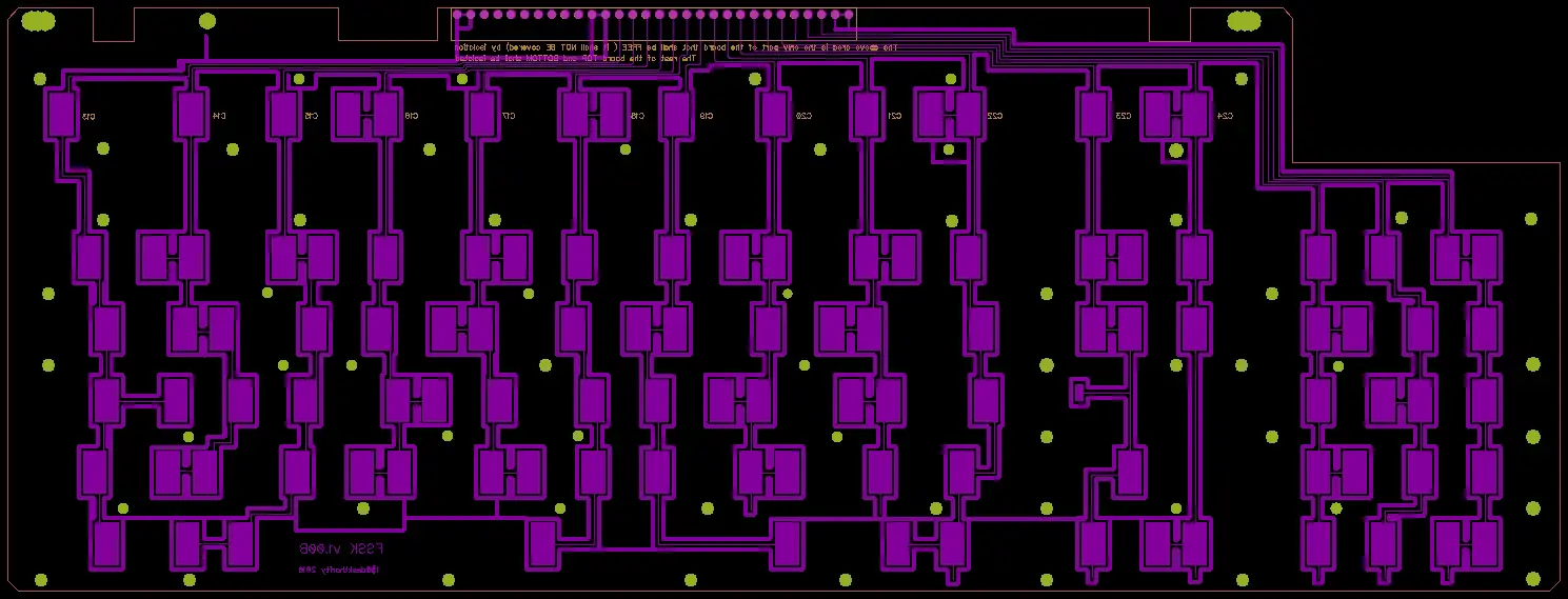
The most important... I received my FEXT PCB from i$ (number 4). It arrived well packaged, and in beautiful shape. Thanks again for all of your work. I can't wait to dive into it
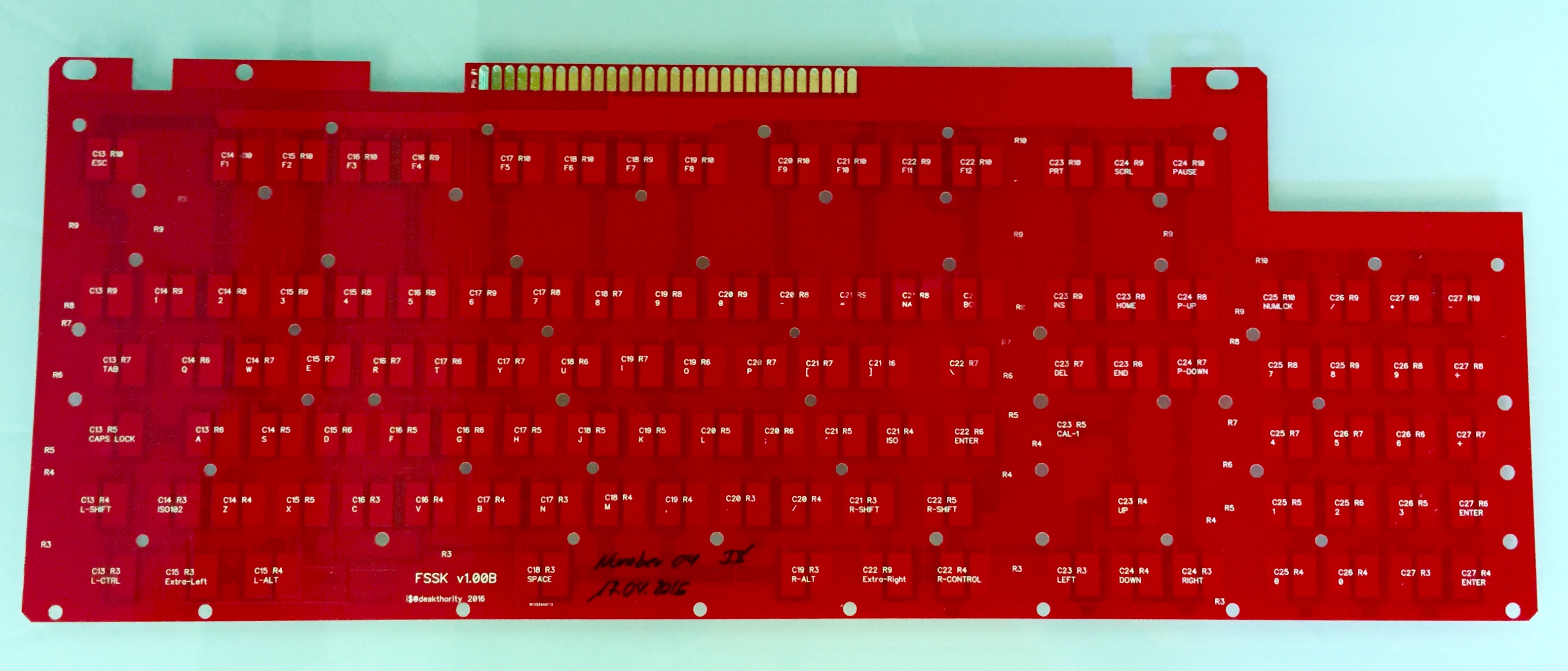
- FullSizeRender_12.jpg (587.78 KiB) Viewed 5333 times
Also, I received my prints for the spacebar stabilizer barrels, the flipper, and the Cherry MX adapter mounts (standard key and spacebar). I am really pleased with the quality of the prints, with an exception of the stem portion for the Cherry spacebar adapter. It arrived warped (I have let Shapeways know, and they are sending a replacement). The action on all of these parts is very smooth (little if any difference from the standard stems and barrels). You will notice occasional artifacts hanging off the print edges in the pics, but this is just a part of the printing process that needs to be tidied up (not in the original designs, and wouldn't be present in molds).
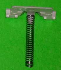
Stabilizer Barrels (Spacebar)
I am finally getting to test the stabilizer barrel concept (barrel with integrated clip vs. independent clip on the top plate), and it is everything I hoped it would be. Barrel tolerance on the keystem is ideal, and the action of the spacebar stabilizer inside the clip is secure but glides freely. There will not need to be any additional adjustments made.
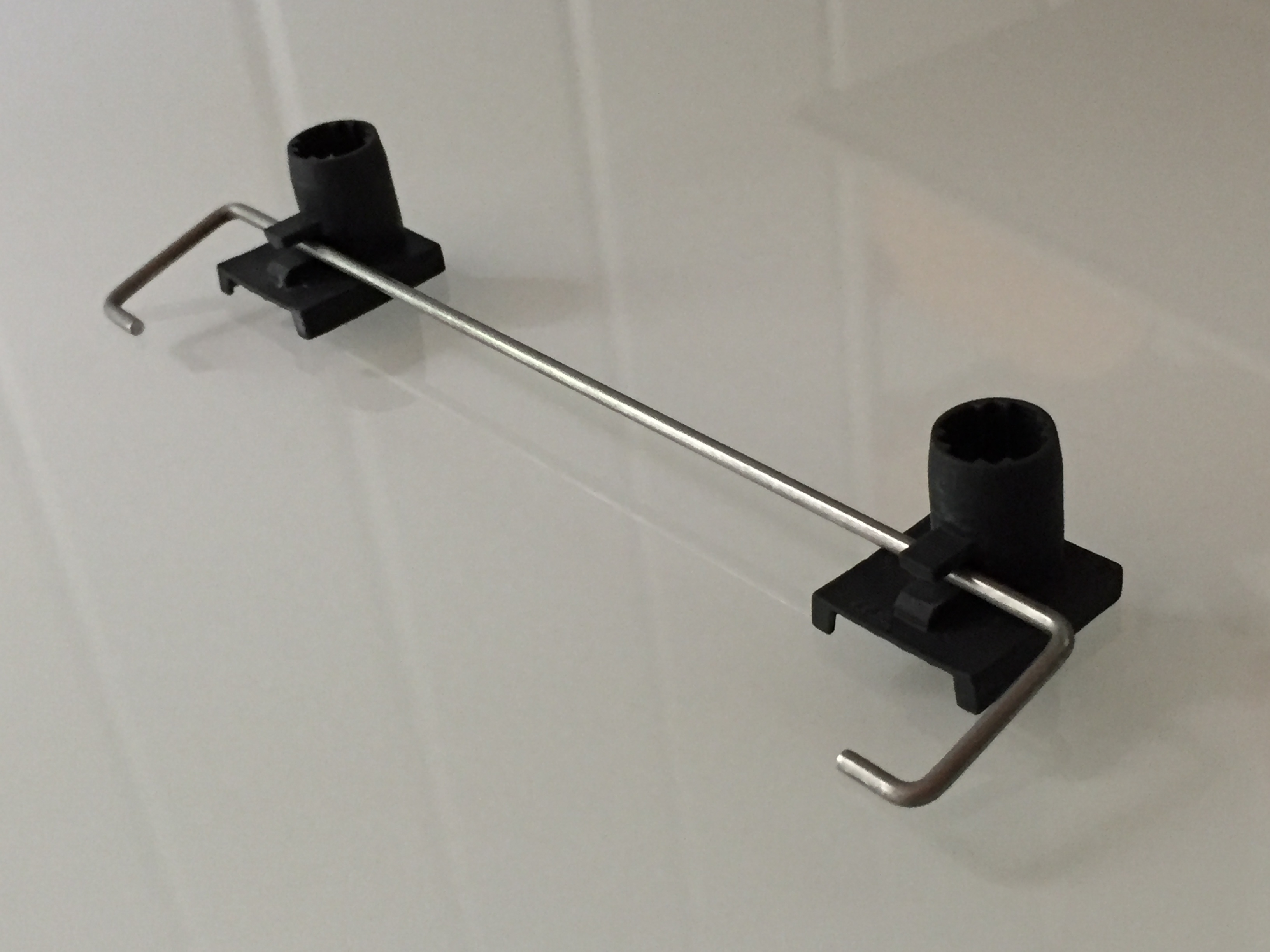
- IMG_7289.JPG (884.52 KiB) Viewed 5333 times
Additional photos
Flipper
The angle and action of the flipper is nice and crisp, and I can not tell any discernible difference between the dimensions of the original and the reproduction. We won't actually know how effective it is until produced from a conductive plastic (still waiting on results from the lab for FTIR testing).
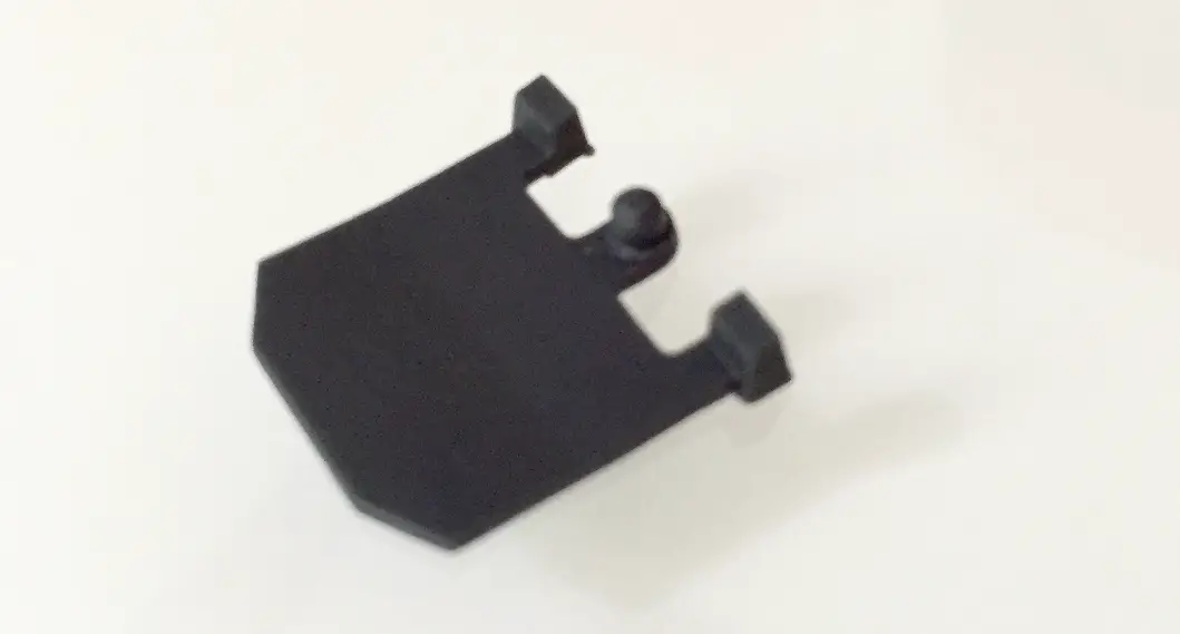
- FullSizeRender_1.jpg (344.19 KiB) Viewed 5333 times
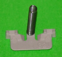
Cherry MX keystem adapter (standard)
Finally getting to test the Cherry MX mount itself against a real physical SA key is a treat. The fit is secure, but easily able to be removed (leaving the keystem in the barrel). The action is now perfect (or I close as I can get it), and very smooth. I do have the opportunity to lower the key profile ~2mm into the stem further, and will take advantage of that (these SA caps sit up high). I think I will split the difference between the SA and DSA profiles (as compared to the IBM key profile) so that either could be used if desired. I will report back when the new print with profile changes comes in (assume 2+ weeks).
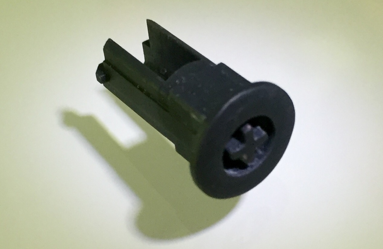
- FullSizeRender_8.jpg (400.3 KiB) Viewed 5333 times
Additional photo
Along with the prints, I received all the M2/M3 screw hardware from Fastenal. I am experimenting with several different screw lengths to find the best combination of lower profile while still making the assembly easy. The screws will be tapped into the top plate (countersunk in the bottom plate). This is different from the original plastic prints since there wasn't enough "meat" to support a screw tap.
The FEXT water-cut top plate is scheduled to deliver tomorrow (the bottom plate I have already made). I should have updates regarding both the FSSK and FEXT metal plate assemblies this week. Stay tuned...