CommonSense: matrix LCR meter with a HID interface

User avatar
DMA

23 Sep 2017, 19:17

tigpha wrote: The Flight Controller code needed a few alterations before it succeeded. I want to share those with you to be sure that I didn't make foolish assumptions. Please can you suggest how we can share and review code?
Private messages or dma@ya.ru. But note first, it's a non-goal to make those compile on older qt or ubuntu. 16.04 is the oldest I'll consider, because why would one even consider running old, unsupported crap, if the upgrade is free?
tigpha wrote: The next hurdle is understanding the pin mapping, and which pins on the CY8CKIT are connected to rows and which are the columns. The diagram in PSoC Creator didn't offer a clue. You describe a Recommended Pinout which I will follow. The order of the rows and columns are irrelevant, I suppose, since this is configured using the Flight Controller. I'll try to draw up a set of diagrams and h/w assembly instructions as I progress...
Pins tab in .cydwr is where you want to look. Rows_X and Cols_X are rows and columns, you'll need to assign corresponding pins to those there. Order matters. Early versions had row and column reordering in FlightController, but the resulting layout and threshold map transformations were too wild, so I removed that.

tigpha

24 Sep 2017, 21:49

Goodbye analogue SCART, I doubt you will ever be used again, HDMI stole your throne
Goodbye-SCART.jpg
Goodbye-SCART.jpg (46.53 KiB) Viewed 7344 times
Hello twenty colour varieties of hookup wire :-)
Goodbye-SCART-hello-20-wires.jpg
Goodbye-SCART-hello-20-wires.jpg (81.78 KiB) Viewed 7344 times
Plenty enough for columns and rows. More variety than can be found in CAT5, and at no extra cost.

tigpha

24 Sep 2017, 22:25

The sacrificial IBM PC XT happens to have eight rows and twelve columns -- coincidentally matching the 20 wires in a SCART cable.
Eight-row-twelve-columns.jpg
Eight-row-twelve-columns.jpg (83.21 KiB) Viewed 7333 times
The PCB shows significant rot, the black areas beneath the green solder mask is cupric oxide. It doesn't look too bad, I don't think that the PCB is electrically compromised. This keyboard was manufactured in the UK, not in the USA. The USA keyboards appear to be better quality built that the UK ones.

User avatar
DMA

24 Sep 2017, 22:33

tigpha,
1) the last photo - did you cut the traces on the keyboard side, or is that line just the line? You'll need to cut those traces so that those tinned points are connected to keyboard, not controller.
2) you're one wire short - you'll need ground. Connected to both PCB ground and the metal frame around the PCB. I also updated the readme about column mapping. You want Col[12] to Col[23] to be mapped to the keyboard columns, left to right. If you just got the firmware and it's a single-ADC variety. Dual-ADC (like, 3 commits ago) is trickier, see readme.

User avatar
DMA

25 Sep 2017, 00:31

cs-mf-tqfp-final1.png
cs-mf-tqfp-final1.png (44.06 KiB) Viewed 7294 times
Final touches - legends, chip moved a bit farther from the USB connector, pads for the "force bootloader" button added. I think that's it, ready for the prime time. Just need to test the prototype with the actual keyboard.

One question still bothers me though. Does it worth extra $3 to make scanning 2x faster? (from 3000 scans per second to 6000 scans per second). The difference is detecting the keypress after 1ms vs 2ms. Probably not noticeable even.

tigpha

25 Sep 2017, 17:19

DMA wrote: tigpha,
1) the last photo - did you cut the traces on the keyboard side, or is that line just the line? You'll need to cut those traces so that those tinned points are connected to keyboard, not controller.
2) you're one wire short - you'll need ground. Connected to both PCB ground and the metal frame around the PCB. I also updated the readme about column mapping. You want Col[12] to Col[23] to be mapped to the keyboard columns, left to right. If you just got the firmware and it's a single-ADC variety. Dual-ADC (like, 3 commits ago) is trickier, see readme.
Hi DMA,

1) It's only corrosion of the iron plates and muck that marks the PCB solder mask layer. I've not cut anything yet, and yes the cut will be above not below the line of tinned vias. It will be a chop to entirely remove the existing controller too, avoiding potential electrical influence of those components;

2) The SCART has 20 signal wires, plus shield ground wire which is bare and made contact with the aluminium foil shield of the donor cable. I have spools of other extra wire, and I'll be sure to connect ground at both ends and to the iron plates too. I remember you mentioning how sensitive grounding can be. Would star-ground be best?

Was the dual ADC the differential-pair experiment I recall you tried? Am I correct recalling that it wasn't really as effective as you had hoped?

Does the geometry of the cable bear any influence? Would a flat ribbon cable be better suited, or will a mad tangle of wires perform just as well? Might be an experiment for me to try...

User avatar
DMA

26 Sep 2017, 03:25

tigpha wrote: I remember you mentioning how sensitive grounding can be. Would star-ground be best?
Theoretically yes, but in practice just the ground is OK. As long as it's there. Actually I even tried to run with PCB ground disconnected - not much difference (though noticeable in matrix monitor - more crosstalk between keys pressed).
tigpha wrote: Was the dual ADC the differential-pair experiment I recall you tried? Am I correct recalling that it wasn't really as effective as you had hoped?
Nope, just parallel reading of the current row using 2 ADCs which are available in 56xx and 58xx SKUs. Anyway, probably should abandon the idea, as PSoC 6 only has one ADC anyway (though twice as fast one).[/quote]

tigpha wrote: Does the geometry of the cable bear any influence? Would a flat ribbon cable be better suited, or will a mad tangle of wires perform just as well? Might be an experiment for me to try...
Depends on how long you want that cable to be. I'd say "doesn't matter for less than 2 feet". I'd keep rows tangle separated from columns tangle to keep that "unpressed" state nice and shiny zero. Worst case (row X and column Y are right next to each other for the whole length) readings will just shift up (i.e. 0-10 to 10-20) for "X,Y" cell in the matrix.

User avatar
DMA

12 Nov 2017, 00:59

I'm typing this on the fastest USB keyboard this side of the Missisipi (at least according to dan luu kekekeke).
The latency between click and USB packet is 1 ms
Solenoid_response.png
Solenoid_response.png (47.14 KiB) Viewed 7120 times
Well, may be 2. But not more that's for sure. The signal is coming out of solenoid control. Solenoid control works in the same loop as USB communications.

The keyboard itself is Muirium's XTant - I found the time to assemble it and compile a CS version for it, based on the proto kit. So if XTant owners want to try - it's just $10 and couple of hours soldering :)
XTant.jpg
XTant.jpg (87.06 KiB) Viewed 7120 times
Anyone knows how to make a spacebar to be more solid? Those washer retention clips are not ideal.

User avatar
wcass

12 Nov 2017, 06:33

DMA wrote: Anyone knows how to make a spacebar to be more solid? Those washer retention clips are not ideal.
Maybe a "retaining washer" that would actually grab hold of the barrel. Something like this:
Image

User avatar
DMA

13 Nov 2017, 05:04

Actually made washer retaining by putting electrical tape over the inside. Works like a charm!

User avatar
DMA

14 Nov 2017, 05:47

First day of field testing went absolutely uneventful. It just works. Not a single hiccup.

User avatar
alh84001
v.001

23 Nov 2017, 20:40

DMA wrote: Anyone knows how to make a spacebar to be more solid? Those washer retention clips are not ideal.
On my XTant I use binder clips handles on one side to clamp down on the stabiliser wire and I'm quite satisfied with the result.

Image
Image

User avatar
DMA

23 Nov 2017, 20:55

alh84001 thanks for the reply. I found out that wrapping those washers into electrical tape provide enough retention force :)

In other news - in 10 days just a couple of double actuations (not sure if those weren't actual physical double presses though). Should probably switch to IIR3/4 instead of wicked fast IIR1/2.

Still no macro editor though - don't feel any need for macros, Fn keys are just fine :)

tigpha

25 Nov 2017, 21:52

Hi DMA, May I ask if my understanding is correct, regarding the connections, please?
Soldering schematic
Soldering schematic
drawing.png (483.87 KiB) Viewed 7042 times

User avatar
DMA

26 Nov 2017, 01:40

tigpha wrote: Hi DMA, May I ask if my understanding is correct, regarding the connections, please?
LGTM - just don't forget the ground sink connection - pin marked as D0 in schematics. You may connect it to P0.3 or P3.2 which you are grounding already.

Though if you're trying to make controller for XTant and want to save some mousing, check out pin assignment in current github revision of commonsense. Note that columns are going in ascending order, but aligned to the high side - so Cols[12] is column 1 and Cols[23] is column 12 for 12-column matrix. (Cols[8] is the first column for 16-column matrix)

tigpha

26 Nov 2017, 18:41

Hi DMA, thanks for confirming. I suppose the column you order that you mentioned is important only if I'm attempting to reuse an existing configuration? In my case, the columns are likely to be in random order, so I expect to be spending time learning how to use FlightController :-)

User avatar
DMA

26 Nov 2017, 20:34

tigpha wrote: Hi DMA, thanks for confirming. I suppose the column you order that you mentioned is important only if I'm attempting to reuse an existing configuration? In my case, the columns are likely to be in random order, so I expect to be spending time learning how to use FlightController :-)
Rows can be assigned to any pin (except ones with capacitors on the proto kit!), columns - any except P12 and ones with capacitors.
Those are assigned in PSoC creator, not FC.

FC deals with already mapped matrix, no remapping there.

User avatar
dorkvader

03 Dec 2017, 18:31

wcass wrote:
DMA wrote: Anyone knows how to make a spacebar to be more solid? Those washer retention clips are not ideal.
Maybe a "retaining washer" that would actually grab hold of the barrel. Something like this:
Image
I have been using teflon washers with some success.
The key is that teflon is somewhat stretchable, so it grips the barrel very nicely and doesn't move.
https://geekhack.org/index.php?topic=79 ... msg2046808

If you want some help prototyping, I can solder SMD and have almost every model F out there, and I don't mind modifying them. I have 4704-100 (50 key) 4702-200 (62-key) and 4704-300 (107 key) about 10 XT, 1 model C, and two 122-key. I can't find my AT right now though. I don't have a 4704-300 (77 key) or a displaywriter model F. I'd really like to get my 4704's working on USB.

User avatar
DMA

03 Dec 2017, 20:15

Thanks for chiming in, dorkvader. 3 small pieces of electrical tape 120 degrees apart worked perfectly (at least they're working perfectly for already what, 3 weeks? Long enough for me).
I'm using that XTant as my primary keyboard at work. It's a pretty uneventful experience.

If you want to convert your 4704 to USB - get yourself one of these and get a windows machine for programming. Flight Controller app works on mac and linux and supports firmware updates, but first you need to flash firmware using cypress windows-only utils.
I'll check if it's possible to run cypress stuff using VirtualBox when I have time. Should be doable. Parallels Desktop is an Officially Supported Configuration.

Note that there's no macro editor still - can't get myself to write it for some reason. But custom layouts, layers, and in theory even solenoid support is there. In theory - because I don't have a board with solenoid, so no means to test.

User avatar
wcass

04 Dec 2017, 02:28

I think a tutorial would be very useful. Cover things like ...
  • choosing what pins for sense, signal, ground, and lock LEDs
    where to change the code for your pin choices
    assigning key values
A video tutorial might be easiest to make. Just record it as you do it. OBS Studio.

User avatar
DMA

04 Dec 2017, 02:37

wcass wrote: A video tutorial might be easiest to make. Just record it as you do it. OBS Studio.
I have yet to see a single useful video tutorial. I need to bribe myself into making screenshots and marking them with "look here" arrows. But right now I just can't. Not that I have lots of stuff to do - just don't want to do anything, y'know :( Winter sucks. Also, __red__ was able to do this from existing docs with minimal guidance and I updated those after his run so I think there's not much need for pictures and especially videos.

__red__

04 Dec 2017, 16:31

You know what, I'll do a video tutorial. It's the least I can do to support the project after DMA did all that work. Give me a day or two.

tigpha

04 Dec 2017, 16:58

Hi __red__, let me know if the pin-out diagram I drew above needs refinement too. My progress is glacially slow, but drawing doesn't take me much time or effort...

__red__

05 Dec 2017, 21:53

tigpha wrote: Hi __red__, let me know if the pin-out diagram I drew above needs refinement too. My progress is glacially slow, but drawing doesn't take me much time or effort...
Thanks! I ended up having to re-map mine because the pinout that DMA was using at the time I did my last build was for his custom hardware.

Going to see what I can put together this evening.

User avatar
DMA

12 Dec 2017, 05:04

Over this weekend I overhauled the scanning module.
XTant turned out to be quite a temperamental beast and I started seeing double actuations and sometimes even "d3f" when quicky typing "df". Scoping showed wildly fluctuating voltages when "d" key is pressed - discharge periods I had were not enough to pull the line all the way to the ground. Had to add 10us wait after reading to quiet those down. Also seems like some keys (but not others) physically bounce on keypress, causing double actuations.
So I implemented slightly modified algorithm from this document, and it works like a charm, while simplifying threshold management. I use 5 bits for debouncing buffer, so it generates keypress on 4th successive reading above (below for beamspring) threshold. Which takes about 1.5ms.
Bonus is that new debouncing algo uses half as much CPU because of less array lookups.

I also chose not to put the case back, so now I have this on my table:
xtant.jpg
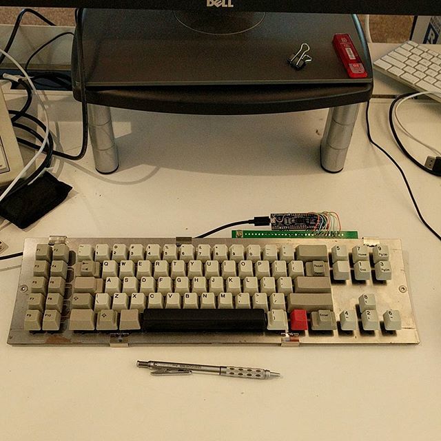
xtant.jpg (72.28 KiB) Viewed 6947 times
For those who already has previous version flashed (__red__, I'm talking about you!) - EXPORT YOUR LAYOUT BEFORE UPGRADING! EEPROM layout has changed, and base layer of the layout uses the space occupied by HiThresholds previously.

tigpha

12 Dec 2017, 11:45

Hi DMA,

I'm using Soarer's controller on two of the Model F 5291 terminal "Bigfoot" I have, and it works very well, very reliable.

The advantage of Soarer's "turbo mode debounce", as I understood it, is that there is no delay to detecting the leading edge of a key press, avoiding the 1.5ms "settling time" delay. The bounces following the trigger leading edge are filtered out. It means that a switch transition has to follow a short period of inactivity, either in "high" or "low" state, but the detection is immediate, not delayed.

For example, in the Bigfoot I'm using now, this quiescent state before a transition is five successive identical samples.

Soarer's description of "turbo mode debounce"

The post containing example code of "Turbo Mode" debouncer.

(edit) Reading the Geekhack thread, I saw that Soarer refers to the same document, and the listing of DebounceSwitch2() function. So maybe my comment is redundant?

User avatar
DMA

13 Dec 2017, 04:15

tigpha wrote: Hi DMA,

I'm using Soarer's controller on two of the Model F 5291 terminal "Bigfoot" I have, and it works very well, very reliable.
But isn't soarer just a protocol converter and, as such, doesn't even need debouncing because actual keyboard controller handles that?
tigpha wrote: The advantage of Soarer's "turbo mode debounce", as I understood it, is that there is no delay to detecting the leading edge of a key press, avoiding the 1.5ms "settling time" delay. The bounces following the trigger leading edge are filtered out. It means that a switch transition has to follow a short period of inactivity, either in "high" or "low" state, but the detection is immediate, not delayed.
It's the other way around. So to trigger to "on" state with five reads the controller should see 01111. Bouncing only happens when you are directly reading switches. Keypress looks like 000001011010010101111111111 - and the trigger is when you have 0, followed by N-1 1s in a row. No way to predict on the first state change that it's a keypress - it can be (and often is!) EMI. But if you see actual scancodes from the keyboard - you don't need debouncing, like, at all. Because keyboard controller already done it.
tigpha wrote: For example, in the Bigfoot I'm using now, this quiescent state before a transition is five successive identical samples.
I doubt you'll notice 5ms difference. Plus, the flipper flies towards the PCB for approximately that duration, so it's a moot point.

The post containing example code of "Turbo Mode" debouncer.
Oh shi. he's debouncing releases, without caring for matrix state. that would lead to lots of release events if EMI is encountered. because 0000000010000000 will eventually turn into "1000" in the buffer and that's "key released".
tigpha wrote: (edit) Reading the Geekhack thread, I saw that Soarer refers to the same document, and the listing of DebounceSwitch2() function. So maybe my comment is redundant?
Soarer's debouncing is _based_ on that function, but the implementation posted doesn't work. I know, because I implemented it in exactly the same way (only shifting left instead of right, and without "turbo mode") - and boy that thing is noisy. Key release events are flooding everything when keyboard is at rest.

User avatar
Halvar

13 Dec 2017, 08:30

Soarer wrote both a controller and an AT converter, these are two separate programs. The 5291 can be made to work with Soarer's controller, but it's used as kind of a converter for the output of the IBM capacitive sensing chips. I'm not sure if the IBM chips handle debouncing, but I don't think so.

User avatar
DMA

13 Dec 2017, 16:46

Then the code in controller is not what's published. Or everyone is extremely lucky and there's no EMI whatsoever and you never read a keypress when there's no keypress.
I fought damn EMI like 2 days ago, I know what I'm talking about.

HuBandiT

13 Dec 2017, 17:40

DMA wrote: I fought damn EMI like 2 days ago, I know what I'm talking about.
Don't despair, Soarer's efforts were directed towards the much less noise-prone resistive keys, not capacitive like you do. Or am I mistaken?

Are you also experiencing EMI while not scanning?

Post Reply

Return to “Workshop”