As it happens, I was up to something similar recently. And it worked. The keyboard I was converting was an
Access-IS matrix POS board (with the proprietary PS/2 programmable controller from hell). Damn thing was utterly useless until I popped in a Teensy. Works a treat now.
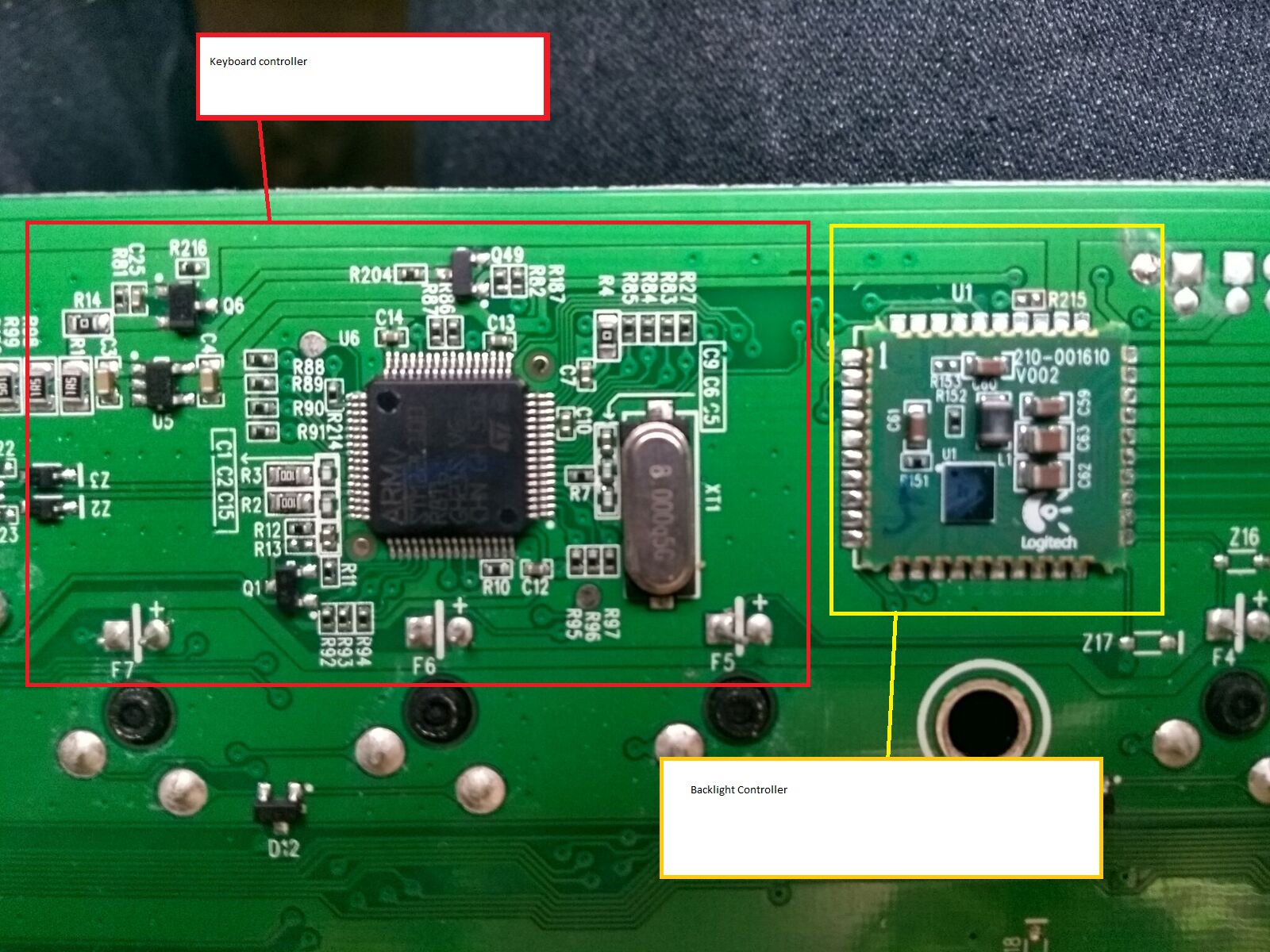
Fortunately, it had a modular design. I simply removed the original controller.
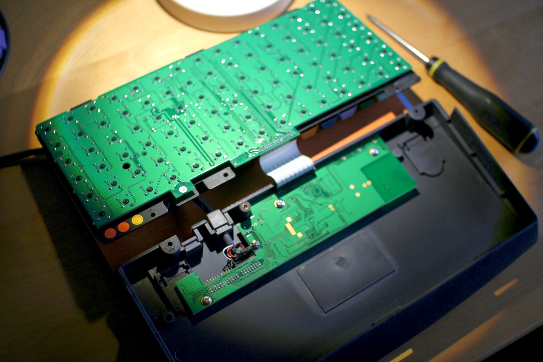
Then instead of hooking up a Teensy to the ribbon connector, I jumped it onto nice big easy solder joints on well chosen switches. Yes, switch pins for both rows and columns. How so? Well, keyboard matrices work like this:

The columns on that diagram are obvious. Just pick a conveniently located switch pin from each one of those lines.
The rows work the same way. But what about the diodes? I’m not trained in electronics, but I found I could ignore them. Just act as though they’re not present. The diodes are about blocking false signals (
masking and ghosting). Real signals pass through them as designed. So don’t worry about them and go pick a convenient pin for each row, too. (If I’m wrong, feel free to correct me. Maybe this only works half the time, depending on diode orientation?)
Once you’re all soldered up, you configure your Teensy’s keyboard controller firmware: telling TMK or Soarer’s Controller (my pick, as I’m used to his tools) which pins are rows and which are columns. If no key presses show up, swap them around. I got the Access conversion right on the first attempt (all 96 switches present, correct, and NKRO!) which says something for this being fairly easy in practice.
Now! There is one difference with what you’re doing. You guys have an integrated controller you want to work around. I’ll be interested to see how you do that. I’ve several boards of my own with controllers right on the switch PCB that I’d like to replace, especially for Bluetooth conversion.