Working on learning..... My first keyboard project....
My question is the sizing of the Cherry MX hole to be cut.
Looking through the forum and on the web, I have noticed two different size holes being used. Though i do not know if the difference is enough to cause an issue. There was a comment or two regarding loose switches that had a tendency to pop out or wobble.
I would like to have a snug fit that will hold the key in place and not be wobbly with a good firm snap in. The measurements posted have been 14mm W x L for an H cut pattern and 13.8507mm.
Can the smaller dimension of 13.8507 be used or would this be too small and cause problems? Or is it too insignificant a difference?
If you used a different dimension than the two listed above, what did you use and where you happy with the result?
Thank you in advance.
Custom Cherry MX plate measurements.
-
q11q11
- Location: --
- DT Pro Member: -
Minus 0.15mm for mounting hole is waaaaaay to much.
You won't be able to fit MX-compat switch into 13.85mm
Else you will get switch at least deformed and not able to function properly, stem will stuck.
I have faced this when I was trying to cut 14x14mm holes manually.
Also I was ordering mounting plate cut for ALPS-type switches (size is 15.5x12.8mm) and was trying to use some china clone switches (which for some weird china cheap reason are about 15.52x12.82mm +/-0.01) - while physically putting switch into hole looks like its juuuuust about to fit, but I couldn't do it w/o breaking/deforming switch.
What I wanted to say with this exmaple - hole should be 14x14mm exact, OR maaaaaybe with big approximation it can be from 13.95x13.95mm to 14.05x14.05mm as standards says so.
Also, for the begining you don't really need complex holes, just squares will be pretty much suitable.
You won't be able to fit MX-compat switch into 13.85mm
Else you will get switch at least deformed and not able to function properly, stem will stuck.
I have faced this when I was trying to cut 14x14mm holes manually.
Also I was ordering mounting plate cut for ALPS-type switches (size is 15.5x12.8mm) and was trying to use some china clone switches (which for some weird china cheap reason
What I wanted to say with this exmaple - hole should be 14x14mm exact, OR maaaaaybe with big approximation it can be from 13.95x13.95mm to 14.05x14.05mm as standards says so.
Also, for the begining you don't really need complex holes, just squares will be pretty much suitable.
-
matt3o

- -[°_°]-
- Location: Italy
- Main keyboard: WhiteFox
- Main mouse: Anywhere MX
- Favorite switch: Anything, really
- DT Pro Member: 0030
- Contact:
As per official Cherry specification distance is 19.05mm and switch hole 14mm.
You often see slightly different values on the forums, they are caused by conversion between mm and inches. Use the diagram below as a reference
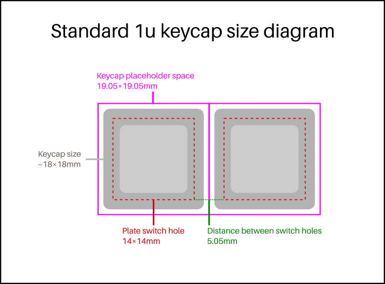
More at https://matt3o.com/anatomy-of-a-keyboard/
You often see slightly different values on the forums, they are caused by conversion between mm and inches. Use the diagram below as a reference
More at https://matt3o.com/anatomy-of-a-keyboard/
-
q11q11
- Location: --
- DT Pro Member: -
According to this doc https://cdn.sparkfun.com/datasheets/Com ... Series.pdf
square mounting hole should have side equal to 0.551in +/-0.002in,
which (by google convertion) is 13.9954mm +/-0.0508mm.
Also I have seen information (on some wiki, but can't find right away) about 0.05mm as non-accumulatung tolerance,
not an addition to distance for every key.
Means that distance between centers of two keys should be 19mm +/-0.05mm.
And sum of distances between centers of 11 keys should be 190mm +/-0.05mm, not 190.5mm.
-
lled3733

- Location: Switzerland
- Main keyboard: Generic mechanical
- Main mouse: Logitech
- Favorite switch: Blue
- DT Pro Member: -
Thank you matt3o and q11q11. I am reading it all. Feels like I am making progress. Easier to work hard at the idea as I tend to get luckier the harder I research. Besides I really want the first project to work. Again thank you both for the input.
-
Findecanor
- Location: Stockholm, Sweden
- DT Pro Member: 0011
No, key spacing is in Imperial but Cherry MX mounting hole size is in metric.
Standard key spacing is defined as 3/4 of an inch, and an inch is 25.4 mm. That translates to 19.05 mm. The decimal part is not a tolerance but part of the number.
The Wiki article on "Unit" quotes an old ISO standard for typewriters from 1967 which defines spacing as 19 ± 1 mm. Typewriter keyboards of 1967 were not as wide as computer keyboards can be are today. For a "full-size" PC keyboard of today which is 22—23 units wide, the difference adds up to 1.1—1.15 mm in total width.
Cherry has published different data sheets. In data sheets for the European market, the MX switch's plate hole is indeed defined as precisely 14 ± 0.05 mm square, with a corner radius of 0.3 mm max.
In data sheets for the US market, they have used measurements converted to Imperial.
-
lled3733
- Location: Switzerland
- Main keyboard: Generic mechanical
- Main mouse: Logitech
- Favorite switch: Blue
- DT Pro Member: -
Btw I should of asked above. What is the purpose the the H pattern cutout vs square. I have heard conflicting stories. Would anyone be able to elaborate? Does it assist w removing of the switch tops once soldered and mounted as I have read? Perhaps something different?
-
Lanrefni
- Location: Vermont
- Main keyboard: BFO-9000
- Main mouse: Logitech G600
- Favorite switch: MX Blues
- DT Pro Member: -
Switch top removal is the reason for the extra cut outs.lled3733 wrote: ↑Btw I should of asked above. What is the purpose the the H pattern cutout vs square. I have heard conflicting stories. Would anyone be able to elaborate? Does it assist w removing of the switch tops once soldered and mounted as I have read? Perhaps something different?
-
Findecanor
- Location: Stockholm, Sweden
- DT Pro Member: 0011
Yes, Cherry MX top and bottom housings snap together with four snaps. Each snap is next to one of the cutouts in the H-shape, allowing the snaps to flex outwards so that the switch can be opened with the bottom still soldered in the keyboard.
Most clones of Cherry MX have snaps patterned on Cherry's but a few clones don't: notably Kailh and Outemu.
I think the first keyboard that had this shape could have been the Phantom TKL. Its PCB also had four holes around each switch's footprint for a tool, but those holes were shown to be unnecessary.
There are a few variations of these switch cutout shapes. One shape is a combination of Cherry MX's 14×14 square hole and Alps' 15.5×12.8 mm rectangular hole for keyboards that support both types of switches. Another allows a Cherry MX switch to be mounted also sideways (looks like a # sign). Yet another shape is more close to an H, for when a plate is machined and your minimum corner radius is larger than 0.3 mm.
BTW. While we are talking about plates: There are three types of stabilisers for Cherry MX, each with different holes. Cherry-style plate-mounted, Costar-style plate-mounted and Cherry PCB-mounted.
There are plate cutout shapes that support either Cherry MX plate-mounted or Costar-style, ... and then there is also a shape (invented by a hobbyist) that combines the two to support your choice of either.
Then there are plate shapes that have quite large rectangular holes for the stabilisers: intended for PCB-mounted stabilisers even though a plate is present. (Otherwise, PCB-mounted stabilisers are for keyboards that have a PCB but no plate). You might find all four variants in various CAD libraries out there.
Last edited by Findecanor on 16 Nov 2018, 08:38, edited 1 time in total.
-
matt3o
- -[°_°]-
- Location: Italy
- Main keyboard: WhiteFox
- Main mouse: Anywhere MX
- Favorite switch: Anything, really
- DT Pro Member: 0030
- Contact:
Reference (official)
- Attachments
-
- Keymodule_MX_EN.pdf
- (579.42 KiB) Downloaded 643 times
-
lled3733
- Location: Switzerland
- Main keyboard: Generic mechanical
- Main mouse: Logitech
- Favorite switch: Blue
- DT Pro Member: -
Thank you all. ''Tis is a drawing from the place I am looking to have the plate made. I will Chang the size from 13.8xxx to the 14mm plus minus .005. My question is regarding the H hole patter. Can I use the measurements indicated in the drawing below in regards to the H step. I have not been able to find the exact drawing but this why I have gathered. I looked at the spec but again I do not find the step size needed. I may just be missing. When I het home I will have some switches to get the measurements from. Again the 13.8056 for the top and side will be adjusted to 14.00 mm.
- Attachments
-
- Catch.jpg (82.22 KiB) Viewed 31894 times
-
FSund

- Main keyboard: ISO Novatouch w/Norbauer alu case
- Main mouse: Logitech G700
- DT Pro Member: -
One reason for this might be if someone was making a design for lasercut acrylic plates. The laser has a certain kerf width (basically the amount of material the laser takes away), so you have to account for this in the design. Some manufacturers do this automatically, some don't.I would like to have a snug fit that will hold the key in place and not be wobbly with a good firm snap in. The measurements posted have been 14mm W x L for an H cut pattern and 13.8507mm.
-
0100010

- Location: DFW TX, US
- Main keyboard: IBM 4704 107
- Main mouse: Trackman FX
- Favorite switch: Buckling Spring
- DT Pro Member: -
Easiest to use KLE, then export that to swills plate tool to create the DXF, then open in an editor to confirm / clean up / modify if needed.