IBM FSSK Build Log

-
Bjerrk

- Location: Copenhagen, Denmark
- Main keyboard: Cherry G80-1800 & Models F & M
- Main mouse: Mouse Keys, Trackpoint, Trackball
- Favorite switch: IBM Buckling Springs+Beamspring, Alps Plate Spring
You're making it sound like this isn't something we've already tried
If anything, I'd say the reverse is true. You have to remember that Euler buckling is very different from ordinary Hookean spring compression. But I'd say that, overall, the feel changes less than you'd think.
(Edit: I take back what I said about Euler buckling
-
Bjerrk
- Location: Copenhagen, Denmark
- Main keyboard: Cherry G80-1800 & Models F & M
- Main mouse: Mouse Keys, Trackpoint, Trackball
- Favorite switch: IBM Buckling Springs+Beamspring, Alps Plate Spring
Of course, if you dip the springs in glowstick juice, they'll get even lighter!
... I'll see myself out ...
... I'll see myself out ...
-
Go-Kart

- Location: England
- Main keyboard: HHKB & AnyKey
- Main mouse: Orochi v2
- Favorite switch: Topre 45 g & MaxiSwitch D/S
-
zrrion

- Location: United States
- Main keyboard: F122
- Main mouse: Microsoft IntelliMouse
- Favorite switch: ALPS SKCC Cream
- DT Pro Member: -
- Contact:
I've heard that loom bands are a decent alternative to floss mod. Haven't tried it myself but as I understand if it's similar to the foam plug method a few folks have used (and at&t patented)
-
ak98
- Location: australia
- Main keyboard: ibm model f xt
- Main mouse: logitech
- Favorite switch: ibm buckling spring
floss is very light and I found that a one cm length of rubber band works better. I used a square profile rubber band that is just wide enough to fit in the spring without falling out when held upside down. I also crytoxed the space bar stab.
PS I did this to one of my XT model F`s but will keep the other original. Sound produced is much more pleasant and no ping/rattle from what was originally a very singy model F.
PS I did this to one of my XT model F`s but will keep the other original. Sound produced is much more pleasant and no ping/rattle from what was originally a very singy model F.
-
raoulduke-esq

- Location: United States
- Main keyboard: Current in the rotation: Silver Badge
- Main mouse: Magic Trackpad 2
- Favorite switch: Capacitive Buckling Spring
3D print resonance channeling to amplify the ping! Trying to reduce ping smfh....
-
idollar

- i$
- Location: Germany (Frankfurt area)
- Main keyboard: IBM F or M
- Favorite switch: BS
- DT Pro Member: -
Hello,
It is a long time since I last posted in deskthority.
Life is complex and I cannot devote all the time that I would like to all my hobbies.
@pyrelink - Your post is extremely nice, complete and accurate. It explains the process of putting together a FSSK as well or even better than the original guide which I posted.
I have been using my (two) FSSKs for years now. I had some problems with the xwhatsit firmware. The calibration has always been somehow an issue for me. Reading your post I came to the xwhatsit version of QMK. Guau viewtopic.php?f=7&t=23406
There has been lot of progress since I started (and paused) in deskthority.
So following the guide that you sent me (thank you pyrelink) I managed to compile and install QMK in my two QMKs.
It has not been an easy process. To start with, the keyboard definition is not equal to the one that is distributed with the sources. I cabled the controllers differently. I used an in-between connector to ensure that I would work better with my prototypes.
I had to remap the rows and columns ... twice. The two FSSKs which I have use different PCB versions. When I designed the FSSK I ordered a first set of two PCBs. It turned out that the design missed a connection which I could patch (literally) with a wire. The second version solved this issue and added additional keys that could be used for the future. It was also used to create the fext
Anyhow, after some effort, I can tell you that I am typing with the prototype this post. It works, I believe, much better.
Finally, let me post a an idea, a promise and a question:
idea: it would be nice to update the PCB with an integrated controller. This will allow to ease the building process. Any interest ?
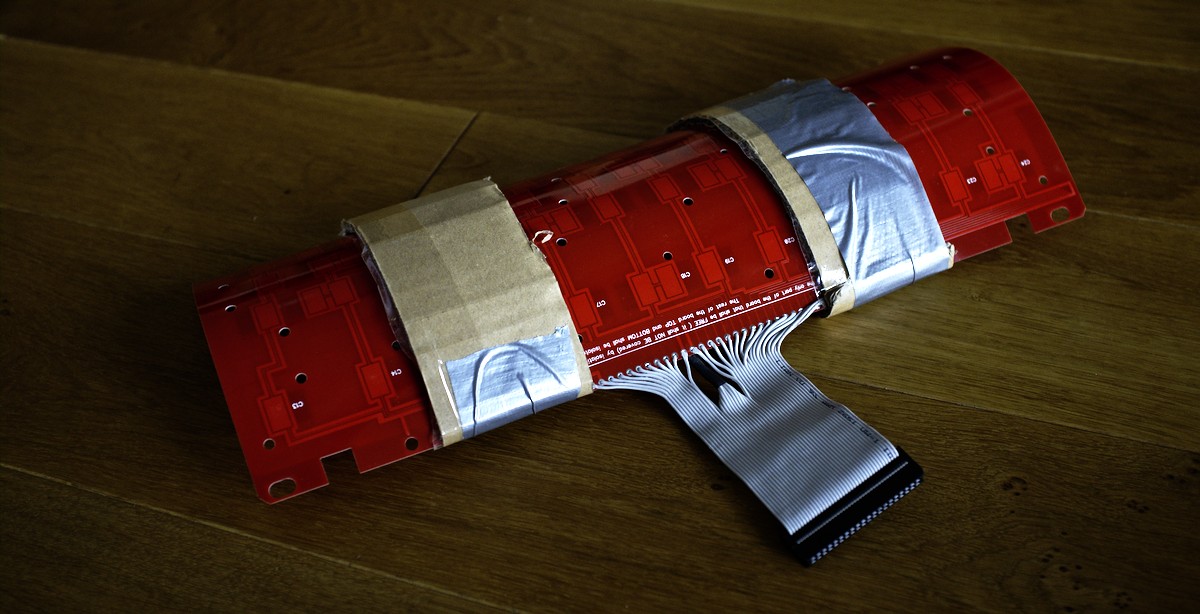
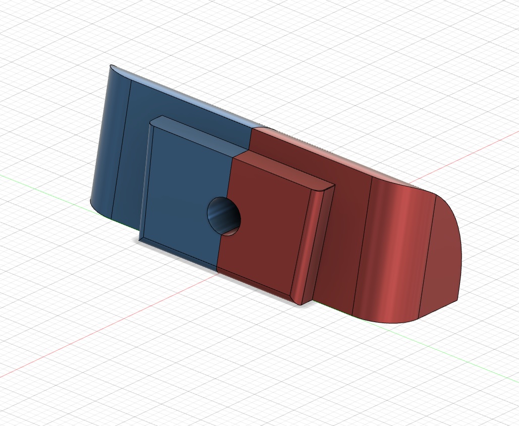
promise: When the original controller is removed and replaced, the usb cable goes through a big hole. I always thought that I could design a 3d-print a piece to make it work as it should. I promise that I will post here the source to print this part once I design it.
question: has someone found a good way to source the F-flippers and springs ? I know this option https://www.modelfkeyboards.com/product/flipperspring/
Once more, thanks a lot !
i$
It is a long time since I last posted in deskthority.
Life is complex and I cannot devote all the time that I would like to all my hobbies.
@pyrelink - Your post is extremely nice, complete and accurate. It explains the process of putting together a FSSK as well or even better than the original guide which I posted.
I have been using my (two) FSSKs for years now. I had some problems with the xwhatsit firmware. The calibration has always been somehow an issue for me. Reading your post I came to the xwhatsit version of QMK. Guau viewtopic.php?f=7&t=23406
There has been lot of progress since I started (and paused) in deskthority.
So following the guide that you sent me (thank you pyrelink) I managed to compile and install QMK in my two QMKs.
It has not been an easy process. To start with, the keyboard definition is not equal to the one that is distributed with the sources. I cabled the controllers differently. I used an in-between connector to ensure that I would work better with my prototypes.
I had to remap the rows and columns ... twice. The two FSSKs which I have use different PCB versions. When I designed the FSSK I ordered a first set of two PCBs. It turned out that the design missed a connection which I could patch (literally) with a wire. The second version solved this issue and added additional keys that could be used for the future. It was also used to create the fext
Anyhow, after some effort, I can tell you that I am typing with the prototype this post. It works, I believe, much better.
Finally, let me post a an idea, a promise and a question:
idea: it would be nice to update the PCB with an integrated controller. This will allow to ease the building process. Any interest ?
promise: When the original controller is removed and replaced, the usb cable goes through a big hole. I always thought that I could design a 3d-print a piece to make it work as it should. I promise that I will post here the source to print this part once I design it.
question: has someone found a good way to source the F-flippers and springs ? I know this option https://www.modelfkeyboards.com/product/flipperspring/
Once more, thanks a lot !
i$
-
pyrelink

- Location: USA
- Main keyboard: HHKB 2
- Main mouse: CST L-Trac
- Favorite switch: Capacitive Buckling Spring
- DT Pro Member: -
Thank you for the kind words i$ and nice to see you back. I’ll have some more words on improving the design later, but aside from some minor glitches, I still adore my FSSK. Thanks for all your hard work.
-
Muirium

- µ
- Location: Edinburgh, Scotland
- Main keyboard: HHKB Type-S with Bluetooth by Hasu
- Main mouse: Apple Magic Mouse
- Favorite switch: Gotta Try 'Em All
- DT Pro Member: µ
Think there’s a lot more of us who were left without any PCB at all. I’ve still an SSK and Model F barrels and flippers set side for this if it ever resumes. 
-
idollar
- i$
- Location: Germany (Frankfurt area)
- Main keyboard: IBM F or M
- Favorite switch: BS
- DT Pro Member: -
Hi Mu,
Ordering the PCBs is the simple part. If there is interest, I can organise it (after Xmas).
I remember that I took special care with the packing. It took some time to get it properly done.
As I said, if there is interest, we could also design a PCB with the controller integrated.
Lets see how the people reacts.
It may be a good motivation to become active again
Cheers
-
pyrelink
- Location: USA
- Main keyboard: HHKB 2
- Main mouse: CST L-Trac
- Favorite switch: Capacitive Buckling Spring
- DT Pro Member: -
Would an integrated controller help with the grounding situation at all? I feel like grounding has always been one of the bigger struggles with getting proper key registrations and no interference. It would definitely simplify the installation process though, and I imagine with proper placement we could reuse the existing connector hole in the case.
-
Muirium
- µ
- Location: Edinburgh, Scotland
- Main keyboard: HHKB Type-S with Bluetooth by Hasu
- Main mouse: Apple Magic Mouse
- Favorite switch: Gotta Try 'Em All
- DT Pro Member: µ
I am so down for that!

The controller is Xwhatsit hardware derived (running Pandrew’s QMK) I presume? I may even have an original Xwhatsit F controller set aside for this, but only 50/50 if I do. Integrated could be smart, so long as someone besides us end users is doing the reflow!
Something I’d crave is a bit of Bluetooth love on this impossible Model MF. Probably asking a bit much of the controller though: capsense and Bluetooth radio stack.
-
idollar
- i$
- Location: Germany (Frankfurt area)
- Main keyboard: IBM F or M
- Favorite switch: BS
- DT Pro Member: -
I do not thing that grounding is a real issue if the keyboard is mounted the right way.pyrelink wrote: ↑09 Dec 2021, 20:43Would an integrated controller help with the grounding situation at all? I feel like grounding has always been one of the bigger struggles with getting proper key registrations and no interference. It would definitely simplify the installation process though, and I imagine with proper placement we could reuse the existing connector hole in the case.
And from what I have seen (and tested so far) the QMK software does a very good job with the calibration and therefore the sensing.
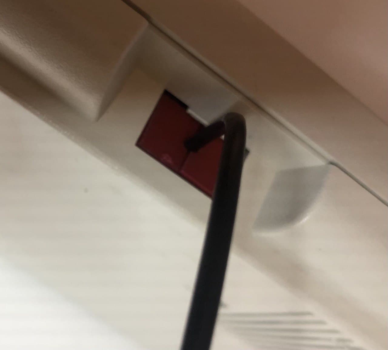
And indeed, one could use the existing connector hole .... BTW ....
Following the part which I designed to hold the cable:
- image1.jpg (250 KiB) Viewed 7852 times
- image2.jpg (237.52 KiB) Viewed 7852 times
- image3.jpg (236.9 KiB) Viewed 7852 times
- image4.jpg (35.99 KiB) Viewed 7852 times
i$
- Attachments
-
- fssk.zip
- (60.01 KiB) Downloaded 104 times
-
pandrew
- Location: Romania
Hey i$!idollar wrote: ↑09 Dec 2021, 19:07So following the guide that you sent me (thank you pyrelink) I managed to compile and install QMK in my two QMKs.
It has not been an easy process. To start with, the keyboard definition is not equal to the one that is distributed with the sources. I cabled the controllers differently. I used an in-between connector to ensure that I would work better with my prototypes.
I had to remap the rows and columns ... twice. The two FSSKs which I have use different PCB versions. When I designed the FSSK I ordered a first set of two PCBs. It turned out that the design missed a connection which I could patch (literally) with a wire. The second version solved this issue and added additional keys that could be used for the future. It was also used to create the fext
Anyhow, after some effort, I can tell you that I am typing with the prototype this post. It works, I believe, much better.
I only implemented support for the FSSK1.0 and FEXT1.0b PCBs I could find pictures for.
I know of at least two people who used my unmodified QMK code with no issue, and no remapping needed, I assume these are the later versions with the fix.
Unfortunately it is a limitation of how QMK works, that it can't just support any arbitrary way to wire up the keyboards without editing source code, because the physical-key-position-to-matrix-position mapping is expected to be embedded into the keyboard source code. In general there are 16! * 8! = 843606888284160000 distinct ways in which a Model F keyboard could be connected, so I must support just one way to do the connection. For beamsprings using a card edge connector, this is easy, cause there is only one way you can mount the controller correctly, so I only have to support one mapping. For model Fs the simplified assumption is that either a ribbon cable is used, where wires can't cross each other (or that the user takes care to keep the ordering of the wires). This works out well with most model Fs, cause there's only one way to wire then correctly. Some times people accidentally cross two wires when soldering, but that's rare, and easy to fix. Where it's a bit more complicated is where you might convert an F XT, or a Displaywriter with a Model F xwhatsit hacked onto it (as opposed to using a real displaywriter xwhatsit). In those cases, there isn't necessarily just one obvious correct way to wire up the connections, so in that case, I can only support one way to make the connections.
In your case, if I understand right, The physical-to-matrix position mapping was wrong for two reasons? One was a different PCB version, and the other was that your in-between connector didn't keep the order of column and row pins, right?
Does anyone else beside you have these older PCB versions, or the same connector pin order? If yes, then I'd be happy to add support for these too to my firmware. However if it's only your prototypes, I'm not sure if it's a good idea, cause it just increases the long list of keyboard variants available via configurator. Let me know what you think.
I have two possible concerns with that:As I said, if there is interest, we could also design a PCB with the controller integrated.
1) For reliability, the controller should be on a portion of the PCB that is not bent, and is free of stresses. I think the Model F XT is a bad example in this case, because the grounding tab that connects the PCB's ground to the backplate via a screw, adds stresses to the controller portion of the PCB, where vias and components are. I think smd components, and modern higher density PCBs would be affected much worse by bends than the XT was. So it really must be in a stress-free area where any vias are or components are mounted.
2) It might be harder to find an assembly house that will do SMD assembly on very thin boards. I've heard about some pcb houses already rejecting thin large F pcbs, even without SMD assembly. I imagine they would have even harder times with pick and place machines and reflow.
Don't take these points as me being a naysayer, I find the idea interesting, and would like to see it. Point1) can be paid attention to during design, and cut-outs could be added to remove stress in some cases. and Point2) is really only about cost, cause I'm sure some assembly houses will accept it, it just might not be the cheapest ones.
For the FSSK we should really support Unicomp's new Mini M, and the additional bottom row keys.added additional keys that could be used for the future.
And for the FEXT I personally want to make a variant that supports all keys of a Unicomp pre-2013 104-key layout.
(For reference https://www.pckeyboard.com/mm5/graphics ... -25-13.pdf)
But for the general public it would also be good to have a variant that supports all keys of the post-2013 104-key layout, cause right now only the 101-key and post-2013 103- key variant is supported as far as I can tell.
I know someone built an FEXT with a pre-2013 104-key Unicomp Classic, with 1 key next to the space bar not working. Technically speaking the second key next to the space bar was also not great, cause it was misaligned, but not so much that it wouldn't work. But even though the misaligned key did work, I think there definitely should be a pre- and post-2013 variant in my opinion (with post-2013 variant also being compatible with classic IBM keyboards)
FSSK design is probably okay post-2013 style only. But a pre-2013 style bottom row on the SSK would be useful for people who are taking a full-size pre-2013 keyboard and cut the assembly down to place it in an SSK or Unicomp Mini M.
I have one concern regarding the FSSK/FEXT project. The currently released files (at least the ones from here) don't have a license attached. Assuming you're the only contributor, could you release them under some open source license? For example a version of Cern OHL v2?
-
idollar
- i$
- Location: Germany (Frankfurt area)
- Main keyboard: IBM F or M
- Favorite switch: BS
- DT Pro Member: -
Hello,
First things first: your work is amassing. Since I joined deskthority I thought about a modular software that could be used with different keyboards. At this time I was not aware of the different technologies under the key sensing. QMK is exactly what I have always dreamt on. The fork to make it work with the IBM keyboards, including my loved model Fs, is absolutely a game changer for me. Thus, I MUST START WITH a) a BIG THANKS and b) ALL MY RESPECT !
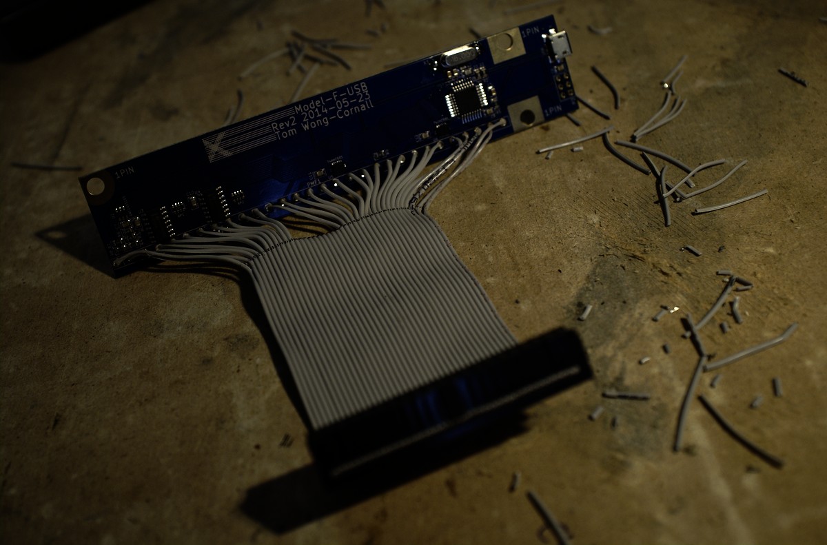
If you take a look at this pyrelink's built:
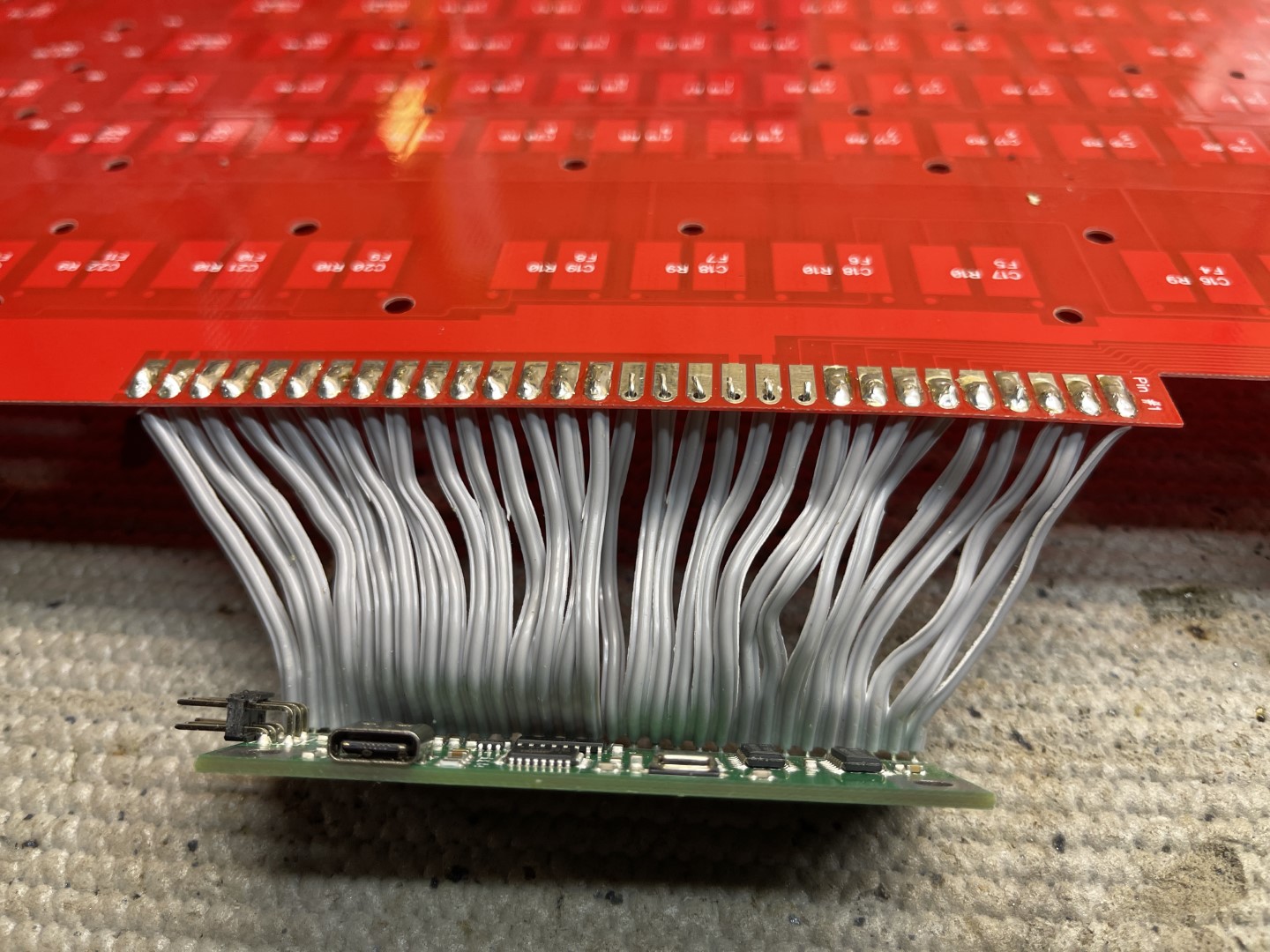
and compare it with mine:
you will notice that there is a "connector" in the middle. This setup swaps the cables but in pairs !
If the "normal" = pyrelink soldering patter is (rows) 1,2,3,4,5,6.... and (columns) a,b,c,d,e,f ... my setup creates a distribution like follows: (2,1),(4,3),(6,5)... and (b,a),(d,c),(f,e) ...
In order to get the keyboards working, I spend most of the time in understanding how the software works.
There is no much documentation within the code
This is how I modified the files:
file: keyboards/fssk_idollar/xwhatsit/xwhatsit.h (the regular PCB):
file: keyboards/fssk_prototype/xwhatsit/xwhatsit.h (there are just two PCBs like this one):
I am attaching the full set of files which I have used also in a zip file.
I include the json file which I used to create my "idollar" keymap with the html configurator.
Just a side comment: I have found very useful to assign the "reset" command to a layer. This allows to enter the boot mode easily to upload a new firmware.
I will continue commenting your very interesting post later. I need to leave now.
MANY THANKS for your work, once more !
i$
First things first: your work is amassing. Since I joined deskthority I thought about a modular software that could be used with different keyboards. At this time I was not aware of the different technologies under the key sensing. QMK is exactly what I have always dreamt on. The fork to make it work with the IBM keyboards, including my loved model Fs, is absolutely a game changer for me. Thus, I MUST START WITH a) a BIG THANKS and b) ALL MY RESPECT !
The issue is mine, your software is correct.For model Fs the simplified assumption is that either a ribbon cable is used, where wires can't cross each other (or that the user takes care to keep the ordering of the wires). This works out well with most model Fs, cause there's only one way to wire then correctly. Some times people accidentally cross two wires when soldering,
If you take a look at this pyrelink's built:
and compare it with mine:
you will notice that there is a "connector" in the middle. This setup swaps the cables but in pairs !
If the "normal" = pyrelink soldering patter is (rows) 1,2,3,4,5,6.... and (columns) a,b,c,d,e,f ... my setup creates a distribution like follows: (2,1),(4,3),(6,5)... and (b,a),(d,c),(f,e) ...
In order to get the keyboards working, I spend most of the time in understanding how the software works.
There is no much documentation within the code
This is how I modified the files:
file: keyboards/fssk_idollar/xwhatsit/xwhatsit.h (the regular PCB):
Code: Select all
#define LAYOUT_all( \
    k_2_2,        k_2_1, k_2_4, k_2_3, k_1_3,     k_2_6, k_2_8, k_1_8, k_2_7,    k_2_5, k_2_10, k_1_9, k_2_9,    k_2_12, k_1_11, k_2_11, \
                                                                                                                                          \
    k_1_2, k_1_1, k_4_1, k_1_4, k_4_4, k_4_3, k_1_6, k_4_6, k_3_8, k_4_7, k_1_5, k_4_5, k_1_10, k_4_10, k_4_9,     k_1_12, k_4_12, k_4_11, \
    k_3_2,     k_6_1, k_3_1, k_3_4, k_3_3, k_6_6, k_3_6, k_6_8, k_3_7, k_6_7, k_3_5, k_3_10, k_6_10,    k_3_9,     k_3_12, k_6_12, k_3_11, \
    k_5_2,       k_6_2, k_5_1, k_5_4, k_5_3, k_6_3, k_5_6, k_5_8, k_5_7, k_5_5, k_6_5, k_5_10, k_8_10,  k_5_9,                            \
    k_8_2,   k_7_1, k_8_1, k_8_4, k_7_3, k_8_3, k_8_6, k_7_6, k_8_8, k_8_7, k_7_5, k_8_5, k_7_10,      k_8_9,             k_8_12,         \
    k_7_2,               k_7_4,                      k_7_8,                        k_7_7,             k_7_9,     k_7_12, k_8_11, k_7_11  \
) \
{ \
    { k_1_1, k_1_2, k_1_3, k_1_4, k_1_5, k_1_6, KC_NO, k_1_8, k_1_9, k_1_10, k_1_11, k_1_12 }, \
    { k_2_1, k_2_2, k_2_3, k_2_4, k_2_5, k_2_6, k_2_7, k_2_8, k_2_9, k_2_10, k_2_11, k_2_12 }, \
    { k_3_1, k_3_2, k_3_3, k_3_4, k_3_5, k_3_6, k_3_7, k_3_8, k_3_9, k_3_10, k_3_11, k_3_12 }, \
    { k_4_1, KC_NO, k_4_3, k_4_4, k_4_5, k_4_6, k_4_7, KC_NO, k_4_9, k_4_10, k_4_11, k_4_12 }, \
    { k_5_1, k_5_2, k_5_3, k_5_4, k_5_5, k_5_6, k_5_7, k_5_8, k_5_9, k_5_10, KC_NO,  KC_NO  }, \
    { k_6_1, k_6_2, k_6_3, KC_NO, k_6_5, k_6_6, k_6_7, k_6_8, KC_NO, k_6_10, KC_NO , k_6_12 }, \
    { KC_NO, k_7_2, k_7_3, k_7_4, k_7_5, k_7_6, k_7_7, k_7_8, k_7_9, k_7_10, k_7_11, k_7_12 }, \
    { k_8_1, k_8_2, k_8_3, k_8_4, k_8_5, k_8_6, k_8_7, k_8_8, k_8_9, KC_NO,  k_8_11, k_8_12 }  \
}Code: Select all
#define LAYOUT_all( \
    k_2_2,        k_2_1, k_2_4, k_2_3, k_1_3,     k_2_6, k_2_5, k_1_5, k_2_8,    k_2_7, k_2_10, k_1_9, k_2_9,    k_2_12, k_1_11, k_2_11, \
                                                                                                                                          \
    k_1_2, k_1_1, k_4_1, k_1_4, k_4_4, k_4_3, k_1_6, k_4_6, k_3_5, k_4_8, k_1_7, k_4_7, k_1_10, k_4_10, k_4_9,     k_1_12, k_4_12, k_4_11, \
    k_3_2,     k_6_1, k_3_1, k_3_4, k_3_3, k_6_6, k_3_6, k_6_5, k_3_8, k_6_8, k_3_7, k_3_10, k_6_10,    k_3_9,     k_3_12, k_6_12, k_3_11, \
    k_5_2,       k_6_2, k_5_1, k_5_4, k_5_3, k_6_3, k_5_6, k_5_5, k_5_8, k_5_7, k_6_7, k_5_10, k_8_10,  k_5_9,                            \
    k_8_2,   k_7_1, k_8_1, k_8_4, k_7_3, k_8_3, k_8_6, k_7_6, k_8_5, k_8_8, k_7_7, k_8_7, k_7_10,      k_8_9,             k_8_12,         \
    k_7_2,               k_7_4,                      k_7_5,                        k_7_8,             k_7_9,     k_7_12, k_8_11, k_7_11  \
) \
{ \
    { k_1_1, k_1_2, k_1_3, k_1_4, k_1_5, k_1_6, k_1_7, KC_NO, k_1_9, k_1_10, k_1_11, k_1_12 }, \
    { k_2_1, k_2_2, k_2_3, k_2_4, k_2_5, k_2_6, k_2_7, k_2_8, k_2_9, k_2_10, k_2_11, k_2_12 }, \
    { k_3_1, k_3_2, k_3_3, k_3_4, k_3_5, k_3_6, k_3_7, k_3_8, k_3_9, k_3_10, k_3_11, k_3_12 }, \
    { k_4_1, KC_NO, k_4_3, k_4_4, KC_NO, k_4_6, k_4_7, k_4_8, k_4_9, k_4_10, k_4_11, k_4_12 }, \
    { k_5_1, k_5_2, k_5_3, k_5_4, k_5_5, k_5_6, k_5_7, k_5_8, k_5_9, k_5_10, KC_NO,  KC_NO  }, \
    { k_6_1, k_6_2, k_6_3, KC_NO, k_6_5, k_6_6, k_6_7, k_6_8, KC_NO, k_6_10, KC_NO , k_6_12 }, \
    { KC_NO, k_7_2, k_7_3, k_7_4, k_7_5, k_7_6, k_7_7, k_7_8, k_7_9, k_7_10, k_7_11, k_7_12 }, \
    { k_8_1, k_8_2, k_8_3, k_8_4, k_8_5, k_8_6, k_8_7, k_8_8, k_8_9, KC_NO,  k_8_11, k_8_12 }  \
}
I include the json file which I used to create my "idollar" keymap with the html configurator.
Just a side comment: I have found very useful to assign the "reset" command to a layer. This allows to enter the boot mode easily to upload a new firmware.
I will continue commenting your very interesting post later. I need to leave now.
MANY THANKS for your work, once more !
i$
- Attachments
-
- qmk_idollar_keyboards.zip
- (78.97 KiB) Downloaded 94 times
-
pandrew
- Location: Romania
There's also leftshift+rightshift+B See here for the feature https://beta.docs.qmk.fm/using-qmk/adva ... re_command
-
pandrew
- Location: Romania
Yes, all that pair swapping makes sense.
I'm thinking in the future one-off keyboards like this should probably go into keyboards/handwired.
Prior to trying to upstream it, I'm planning to move capsense support somewhere into qmk core, so probably into the quantum sub-folder, and that will allow any keyboard to make use of the features, so one-off keyboards would go into for example keyboards/handwired/fssk_idollar, and the one used by multiple people would go into keyboards/ibm/fssk
Don't have time to do that right now, but it's coming up in the future.
-
idollar
- i$
- Location: Germany (Frankfurt area)
- Main keyboard: IBM F or M
- Favorite switch: BS
- DT Pro Member: -
In relation to your text in the post viewtopic.php?p=496582#p496582
The idea behind my post was to provide the community with all the relevant information and documents which I used in creating the PCBs. What I have quickly read fits well with my idea. I have seen that I may need to add some license files to the distribution. Some help in the actual required process will be welcome. If you have some time, you may want to send me a private message to organise the change.
What you are commenting and the proposed solution makes lot of sense.I have one concern regarding the FSSK/FEXT project. The currently released files (at least the ones from here) don't have a license attached. Assuming you're the only contributor, could you release them under some open source license? For example a version of Cern OHL v2?
The idea behind my post was to provide the community with all the relevant information and documents which I used in creating the PCBs. What I have quickly read fits well with my idea. I have seen that I may need to add some license files to the distribution. Some help in the actual required process will be welcome. If you have some time, you may want to send me a private message to organise the change.
-
headphone_jack
- Location: Philadelphia
- Main keyboard: IBM MOPAR FSSK
- Main mouse: Logitech G502 Lightspeed
- Favorite switch: Brown Alps
- Contact:
Yes, an integrated controller would be great. Could even implement reed reset support for disassembly-free reflashing. As for the hole in the case, I think it would be cool to be able to use the original detachable cable over SDL. Making a daughterboard that connects to the controller would be a relatively simple process. Just something to think about!idollar wrote: ↑09 Dec 2021, 19:07
idea: it would be nice to update the PCB with an integrated controller. This will allow to ease the building process. Any interest ?
promise: When the original controller is removed and replaced, the usb cable goes through a big hole. I always thought that I could design a 3d-print a piece to make it work as it should. I promise that I will post here the source to print this part once I design it.
-
idollar
- i$
- Location: Germany (Frankfurt area)
- Main keyboard: IBM F or M
- Favorite switch: BS
- DT Pro Member: -
In relation to the following text marked in black:
it should be possible to integrate a little switch connected to the reset pin ( xwhatsit example here https://lh4.googleusercontent.com/zPPZ0 ... d9pdQ=s800). This will avoid dismantling the keyboard to perform a reset, indeed.
If a different controller is used, it could be connected to the applicable reset pins.
And looking at the part that I designed here:headphone_jack wrote: ↑10 Dec 2021, 15:27
Yes, an integrated controller would be great. Could even implement reed reset support for aqadisassembly-free reflashing. As for the hole in the case, I think it would be cool to be able to use the original detachable cable over SDL. Making a daughterboard that connects to the controller would be a relatively simple process. Just something to think about!
it should be possible to integrate a little switch connected to the reset pin ( xwhatsit example here https://lh4.googleusercontent.com/zPPZ0 ... d9pdQ=s800). This will avoid dismantling the keyboard to perform a reset, indeed.
If a different controller is used, it could be connected to the applicable reset pins.
-
idollar
- i$
- Location: Germany (Frankfurt area)
- Main keyboard: IBM F or M
- Favorite switch: BS
- DT Pro Member: -
My approach is to focus on the functional requirements first and ensure that the "cosmetics" are possible at a later stage. If we try to do everything we may end up achieving nothingheadphone_jack wrote: ↑10 Dec 2021, 15:27
Yes, an integrated controller would be great. Could even implement reed reset support for disassembly-free reflashing. As for the hole in the case, I think it would be cool to be able to use the original detachable cable over SDL. Making a daughterboard that connects to the controller would be a relatively simple process. Just something to think about!
-
idollar
- i$
- Location: Germany (Frankfurt area)
- Main keyboard: IBM F or M
- Favorite switch: BS
- DT Pro Member: -
One additional question:
https://www.youtube.com/watch?v=xCHbd3x13rU
In this video they he is using our FSSK PCB, isn't it ?
An screenshot follows ... it looks like one of the early PCBs (they were green)
https://www.youtube.com/watch?v=xCHbd3x13rU
In this video they he is using our FSSK PCB, isn't it ?
An screenshot follows ... it looks like one of the early PCBs (they were green)
- youtube.jpg (205.81 KiB) Viewed 7625 times
-
Muirium
- µ
- Location: Edinburgh, Scotland
- Main keyboard: HHKB Type-S with Bluetooth by Hasu
- Main mouse: Apple Magic Mouse
- Favorite switch: Gotta Try 'Em All
- DT Pro Member: µ
Definitely want to be able to build one of these without a rat king inside like that. (No offence to the builder, just saying that my handiwork would lead to a tribunal at The Hague.)
Integrated controller then!
Integrated controller then!