Page 7 of 10
Posted: 20 Oct 2015, 18:00
by Plasmodium
ne0phyte wrote: ↑Great to hear that it arrived and it's working!
I packed and shipped four more today (Plasmodium, flabbergast, malcomkern, sinegav)
Wahey!
Posted: 20 Oct 2015, 22:18
by malcomkern
Great, I' am waiting. Whohooooooo
Posted: 21 Oct 2015, 13:06
by sinegav
Me too :DD
Posted: 21 Oct 2015, 13:10
by ne0phyte
Just brought the PCBs for scottc and primered6 to the post office \o/
Posted: 22 Oct 2015, 15:59
by primered6
Yay.. Awesome
Can't wait.
Posted: 22 Oct 2015, 16:03
by scottc
woot
Posted: 22 Oct 2015, 18:48
by malcomkern
Just came home from work and there was a nice envelope waiting for me at the doorstep!
Hobby work to do this evening.
Thanks ne0phyte!
Posted: 22 Oct 2015, 19:59
by Plasmodium
Just out of interest, is it obvious which way round the diodes go? I'm a bit of an electronics noob, and I don't want to have to desolder and resolder all of them if I get it wrong!
Posted: 22 Oct 2015, 20:03
by Muirium
If this picture shows the PCBs diode side up (which I think it does) then those rectangles look like a good sign for "insert diode here", and each of them has a stripe at one end. Just like you'll find on your diodes.

Posted: 22 Oct 2015, 20:04
by RoastPotatoes
Plasmodium wrote: ↑Just out of interest, is it obvious which way round the diodes go? I'm a bit of an electronics noob, and I don't want to have to desolder and resolder all of them if I get it wrong!
ne0phyte did a good job with this. There is a mark for where you need the diodes to go and they have the line on them facing the direction you need them to go.

Posted: 22 Oct 2015, 20:06
by ne0phyte
You guys are too fast for me. Yes, there is a black line on the diode that you just line up with the line on the PCB.
EDIT: That reminds me, I have to change the size of the diode footprint. The pad distance can be a lot smaller for those tiny diodes.

Posted: 22 Oct 2015, 20:08
by RoastPotatoes
I don't think I have seen this on another pcb I have used. It is a nice idea to remove a little doubt.
Posted: 22 Oct 2015, 20:10
by ne0phyte
RoastPotatoes wrote: ↑I don't think I have seen this on another pcb I have used. It is a nice idea to remove a little doubt.
You can always check the pads though. The pad for the cathode end is a rectangle

Posted: 22 Oct 2015, 20:20
by malcomkern
I am missing the 2 22Ohm resistors what supposed to go next to the mini USB on the PCB. I have to go to my local electronics shop tomorrow morning

PCB looks great.
I did all the SMD first, now the diodes and the switches.
@ ne0phyte:
Do I need the USBASP USB ISP Programmer & 10 Pin Ribbon Cable & 6 Pin Converter - AVR ATMEL from ebay to program the first time?
Posted: 22 Oct 2015, 20:24
by ne0phyte
Whaaat did I really forget to put them in your package?

Really sorry about that

Ask for 1206 (3.2x1.6mm) 22Ω ones. I would offer you to send them as a letter but the shipping alone is more expensive than two resistors

Posted: 22 Oct 2015, 20:31
by malcomkern
I go to the shop tomorrow first thing, just let you know.
Do I have to buy the ebay programmer to program the fist time? Then I will order that also tonight.
Posted: 22 Oct 2015, 20:38
by ne0phyte
malcomkern wrote: ↑I go to the shop tomorrow first thing, just let you know.
Do I have to buy the ebay programmer to program the fist time? Then I will order that also tonight.
Yeah, you will need one (and it can't hurt to have one).
It comes with the Atmel DFU bootloader, but the default fuses are configured to divide the clock by 8 (low fuse ckdiv8 bit). That reduces the power usage, but makes it run at 2MHz while TMK expects 16MHz.
Here are the fuses I'm using:
(external 16MHz clock, 4kb bootloader section)
Code: Select all
$ avrdude -U lfuse:w:0xFF:m -U hfuse:w:0xF9:m -U efuse:w:0xCB:m -U lock:w:0x2B:m
I ordered a cheap TQFP44 socket from china. Once I get that I'll be able to prepare the controllers without soldering them.
Posted: 22 Oct 2015, 20:46
by ne0phyte
malcomkern wrote: ↑Do I need the USBASP USB ISP Programmer & 10 Pin Ribbon Cable & 6 Pin Converter - AVR ATMEL from ebay to program the first time?
Oh and you will also need some jumper wires due to my retarded order of ISP pins on the PCB.
I will change the order of those in the next PCB revision.
Posted: 22 Oct 2015, 21:31
by Plasmodium
Thanks all! That's good to know. I did see the rectangles on the PCB, but I didn't see the line at the end!
Posted: 24 Oct 2015, 13:31
by Plasmodium
Just got mine in! Will have a crack at assembling it later in the week - but only if I can get the plate mount for the switches before then, as if I understand correctly, that cannot be put on after the switches are soldered in.
Posted: 24 Oct 2015, 14:55
by flabbergast
Mine got here today as well. Looks excellent! Thanks!
It might take me a while to have a go (school holidays next week + in-laws), but I'll try to take photos along
Posted: 24 Oct 2015, 14:56
by flabbergast
Plasmodium wrote: ↑... as if I understand correctly, that cannot be put on after the switches are soldered in.
Yep, a plate is "sandwiched between" the switches and PCB.
Posted: 24 Oct 2015, 15:00
by Muirium
The race for the slowest build is on!
Plasmodium wrote: ↑if I understand correctly, the plate cannot be put on after the switches are soldered in.
Correct. MX switches clip into a plate from above / feet side first. You can't push a plate down on top of them, no matter how much more convenient that would be when you've already soldered the lot in place!
For a board this small, I'd go without a plate. Anything smaller than TKL is a good candidate for PCB mount, in my view. But it does depend a bit on the case you have in mind. That PCB wants support! A good metal plate can look after itself in that regard, just held from the sides. Acrylic plates are, I suppose, somewhere in between.
Posted: 24 Oct 2015, 15:56
by Plasmodium
Muirium wrote: ↑The race for the slowest build is on!
Plasmodium wrote: ↑if I understand correctly, the plate cannot be put on after the switches are soldered in.
Correct. MX switches clip into a plate from above / feet side first. You can't push a plate down on top of them, no matter how much more convenient that would be when you've already soldered the lot in place!
For a board this small, I'd go without a plate. Anything smaller than TKL is a good candidate for PCB mount, in my view. But it does depend a bit on the case you have in mind. That PCB wants support! A good metal plate can look after itself in that regard, just held from the sides. Acrylic plates are, I suppose, somewhere in between.
The only thing is, this PCB doesn't have mounting holes anywhere. Short of drilling through the PCB (possible, but tricky, and I don't have a drill) to make some, I think plate mount is easier. It doesn't need it for rigidity, sure, but I don't see an easier/more convenient way to mount it. I am open to ideas if you have any though! I totally could just do laser cut acrylic, but you'd need 1.5mm stuff, and I only have 5mm...
Posted: 24 Oct 2015, 16:04
by ne0phyte
Would love to supply you with a mount plate, but I don't have any yet. I have one of my old mount plates left, but I want to keep that (I want to keep one of each PCB/plate revision).
I will check out the Hamburg fablab soon. They have both 2D and 3D CNC mill and a ...laser cutter! Sadly it's only capable of processing wood, acryl, etc..
If you can find someone with a drill and some metal drill bits you could just drill a few ~3mm holes. For now that is probably the easiest and cheapest solution.
I have a cute little cordless drill/driver and I can assure you that it's really easy to drill clean holes in a PCB even if you have never used a drill before

Posted: 24 Oct 2015, 16:28
by Plasmodium
ne0phyte wrote: ↑Would love to supply you with a mount plate, but I don't have any yet. I have one of my old mount plates left, but I want to keep that (I want to keep one of each PCB/plate revision).
I will check out the Hamburg fablab soon. They have both 2D and 3D CNC mill and a ...laser cutter! Sadly it's only capable of processing wood, acryl, etc..
Same here. The Exeter one can only do acrylic (and maybe wood?) in the laser cutter. They also have a CNC machine (I don't know much about CNC machines, but I think it's relatively decent), but all of the volunteers are relatively inexperienced, at least with cutting metal. And they're only in once every 2 weeks!
Surely it'd wouldn't be too hard to make some sort of 3D printed case that the PCB could just clip/screw into...but I don't know the first thing about 3D printing...
Posted: 24 Oct 2015, 17:41
by Muirium
3D printed cases…
Well, I have one of those.
Suka's prototype case for 7bit's HyperMicro PCB:
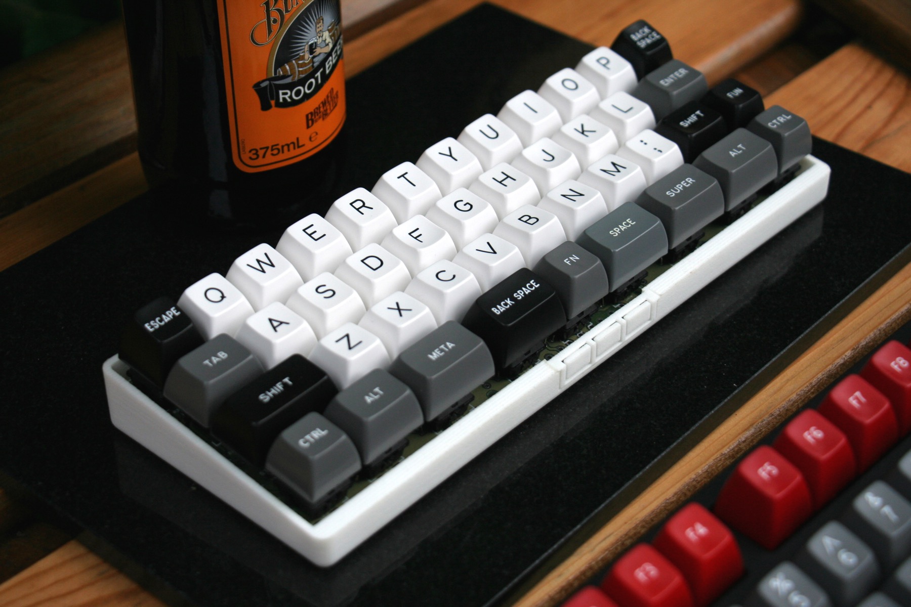
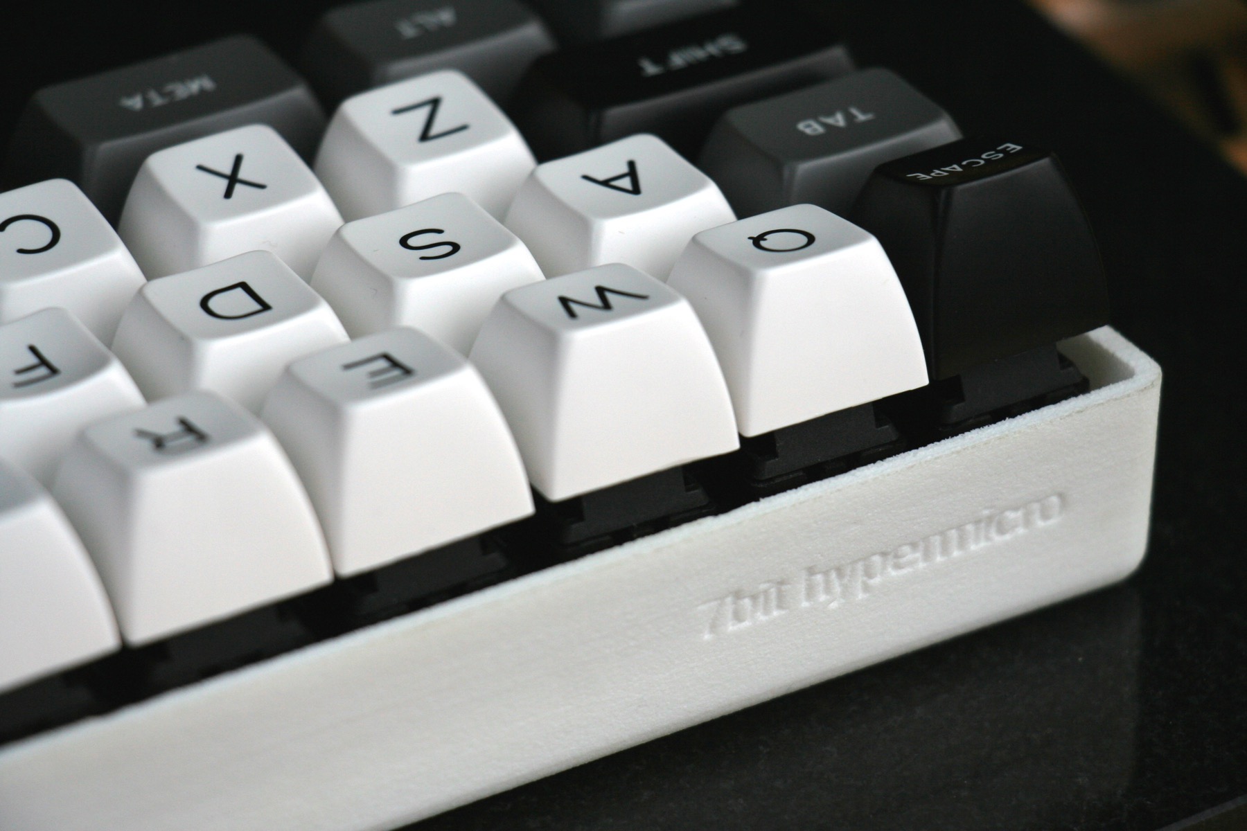
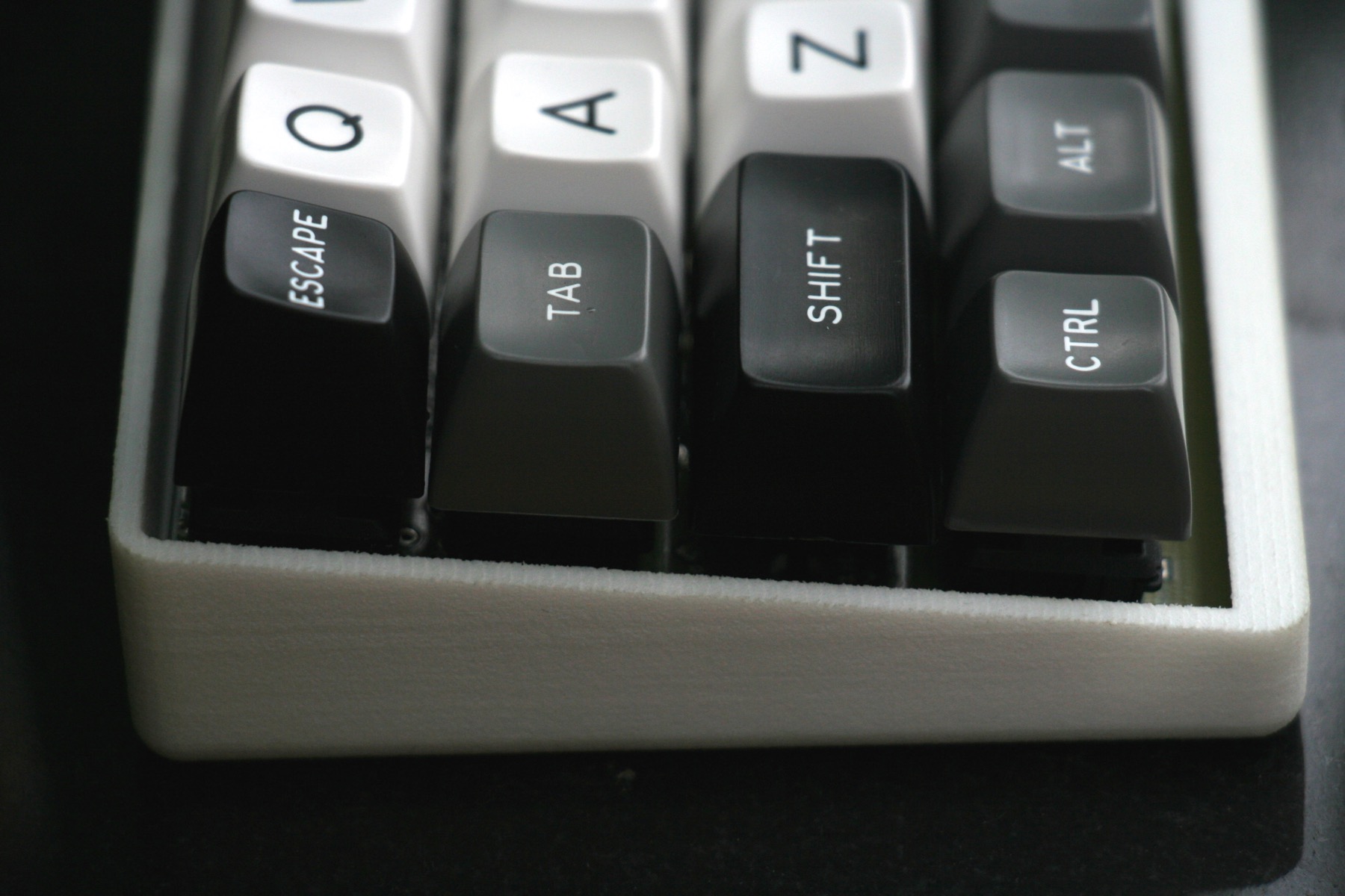
The PCB screws in at a couple of mounting points. It's okay, but (prepare for my usual rant) 3D print material isn't a panacea. It's crumbly stuff, not well suited to bearing loads. I don't feel quite safe with it in these tasks, though whatever Suka used is pretty solid and doesn't seem to have deformed so far. 3D printing is one of those things where people get carried away: OMG 3D PRINTED 3D PRINTERS!! It is pretty good at making keyboard case bodies, though. But the 3D design work is nontrivial, I'm sure, and I'd prefer a more robust mounting system than putting screws straight into this material. Especially when a stiff plate is concerned.
Posted: 25 Oct 2015, 16:23
by malcomkern
Did all the soldering. Not a pro with the SMD stuff but slowly learning. I think all parts are fine now.
If I plug the USB cable in on my windows machine I see a ATm32U4DFU in my Other devices present so there is some communication
Now I wait for the ordered USB programmer, should come on Wednesday or Thursday

Posted: 25 Oct 2015, 16:28
by Muirium
Is that silver component (left of Z) a quartz crystal? Is it low enough to stay out the way of the keycap?
Posted: 25 Oct 2015, 16:58
by malcomkern
Yes it is. Key fits easy, never goes down all the way to the crystal. See photo.