I've seen some of these projects here on DT and GH, but it seems they never went to full scale production or they are specifically crafted for a particular keyboard (or they are not compatible with TMK firmware)
Do you think it would be possible to develop a "keyboard friendly" teensy alternative? Unfortunately I can't work on the design but I can take care of production and sponsor the development.
Ideally the specs I'm thinking are:
- approx 38x18mm
- components on 1 side only
- micro-usb (or usb-c?) on the longer side, I'm thinking it would be nice to place it on a small peninsula so it sticks out a little
- accessible USB pins for easy routing (ie: extension cable)
- at least 2 screw holes
- as many in/out ports as possible of course
- I don't need leds, but if you think it's necessary I'm fine with that
Should we think of some kind of "expansion slot" for future development (namely wireless)?
Ideas? suggestions? volunteers?
Just to be clear, I don't think this is going to cost less than a teensy (depends on quantity), but at least it will be exactly what we need.
Can we design the teensy alternative for keyboards?
-
matt3o

- -[°_°]-
- Location: Italy
- Main keyboard: WhiteFox
- Main mouse: Anywhere MX
- Favorite switch: Anything, really
- DT Pro Member: 0030
- Contact:
-
DiodeHead

- Location: Spain
- Favorite switch: Gateron white
- DT Pro Member: -
Hi matt, well i think some people in this forum are very close to achieve that, flabbergast being one of them in my opinion, he´s working with arm micros and have some very interesting breakout boards right now.
This link he sent me to give me some info on how to start with the k27 from freescale:
https://imgur.com/a/BaKSk
In mass production that board should cost more or less like a pro micro i think, since it has very few components and those micros arent expensive.
I´ve been investigating micros and for the most interensting feature i found is, some of them (im not sure if others brand do this but npx does) if you hold the reset button they will appear in the computer as an massive storage device, and then you only have to copy and paste the firmaware to program it, i think this is a very desirable feature for actualization distribution. and im sure layout configuration can be handled in a similiar manner so is not so dificult for the non programer type.
-
matt3o
- -[°_°]-
- Location: Italy
- Main keyboard: WhiteFox
- Main mouse: Anywhere MX
- Favorite switch: Anything, really
- DT Pro Member: 0030
- Contact:
there are quite some projects of this kind, flabbergast's fails at least in one thing though: components are on both sides.
-
mohitgarg
- Main mouse: R.A.T 7
- Favorite switch: Blue
- DT Pro Member: -
It's a good idea, and one I have toyed around a bit with regack via PM earlier too. we too a slightly different approach and were planning on using a board-to-board connector on one side, so when switching between boards or trial PCBs, just plug out the controller from one, and plug it into the next PCB.
If you want to make something like the Teensy, I can probably give it a shot, one thing though, if we use the TQFP package which is usually used on PCBs with integrated MCU, fitting it in the 18mm width will be impossible, you'll have to go with the QFN package, which is mighty hard to hand solder, so has to be done at the fab. If you feel, that these cna be made available via some vendor(s) and assembled using automated systems at the fab, I can most likely make the PCB and fit everything around the same dimensions as the Teensy. Hit me up if you want to go that route.
If you want to make something like the Teensy, I can probably give it a shot, one thing though, if we use the TQFP package which is usually used on PCBs with integrated MCU, fitting it in the 18mm width will be impossible, you'll have to go with the QFN package, which is mighty hard to hand solder, so has to be done at the fab. If you feel, that these cna be made available via some vendor(s) and assembled using automated systems at the fab, I can most likely make the PCB and fit everything around the same dimensions as the Teensy. Hit me up if you want to go that route.
-
matt3o
- -[°_°]-
- Location: Italy
- Main keyboard: WhiteFox
- Main mouse: Anywhere MX
- Favorite switch: Anything, really
- DT Pro Member: 0030
- Contact:
absolutely! The idea is to have them already assembled in a factory.
Please consider the dimensions I proposed are not final, the smaller the better of course but we need enough i/o and the screw holes.
Please consider the dimensions I proposed are not final, the smaller the better of course
-
Ratfink

- Location: North Carolina, USA
- Main keyboard: IBM Displaywriter
- Main mouse: CST L-Trac
- Favorite switch: Beam Spring
- DT Pro Member: -
Why is putting components on both sides a bad thing? You've said twice now that you see that as a necessary feature, but haven't given any rationale. If it keeps the board smaller in the other two dimensions, I personally don't see it as bad at all to put SMD components on both sides.
-
matt3o
- -[°_°]-
- Location: Italy
- Main keyboard: WhiteFox
- Main mouse: Anywhere MX
- Favorite switch: Anything, really
- DT Pro Member: 0030
- Contact:
the controller board needs to be as flat as possible to reduce the height of the case (especially 60-65% "sandwich" cases). Also having no components on one side lets you put the board flush on the inside of the bottom plate or directly over a PCB.Ratfink wrote: ↑Why is putting components on both sides a bad thing? You've said twice now that you see that as a necessary feature, but haven't given any rationale. If it keeps the board smaller in the other two dimensions, I personally don't see it as bad at all to put SMD components on both sides.
-
mohitgarg
- Main mouse: R.A.T 7
- Favorite switch: Blue
- DT Pro Member: -
Sounds good, I'll give it a shot over this long weekend. If it's assembled at factory, I will most likely use 1206/1210 components to further reduce the footprint and see how to minimize the size while retaining the mount holes and all I/O pins.matt3o wrote: ↑absolutely! The idea is to have them already assembled in a factory.
Please consider the dimensions I proposed are not final, the smaller the better of course
IIRC, assembly is substantially more expensive if components are on both sides of the board, cause it's essentially twice the work for the labor at the factory.
-
matt3o
- -[°_°]-
- Location: Italy
- Main keyboard: WhiteFox
- Main mouse: Anywhere MX
- Favorite switch: Anything, really
- DT Pro Member: 0030
- Contact:
\o/mohitgarg wrote: ↑ Sounds good, I'll give it a shot over this long weekend. If it's assembled at factory, I will most likely use 1206/1210 components to further reduce the footprint and see how to minimize the size while retaining the mount holes and all I/O pins.
add it to the 101 reasons to have components on just one sidemohitgarg wrote: ↑IIRC, assembly is substantially more expensive if components are on both sides of the board, cause it's essentially twice the work for the labor at the factory.
oh, of course we need a reset button... or actually any way to put the controller in flash mode (we could just short two headers)
-
vvp

- Main keyboard: Katy/K84CS
- Main mouse: symetric 5-buttons + wheel
- Favorite switch: Cherry MX
- DT Pro Member: -
If you want really small size then you can use a microcontroller which does not require crystal for USB. At least ATXMega and STM32F0x2 do not need a crystal. I'm sure there are much more.
-
matt3o
- -[°_°]-
- Location: Italy
- Main keyboard: WhiteFox
- Main mouse: Anywhere MX
- Favorite switch: Anything, really
- DT Pro Member: 0030
- Contact:
using a different chip is definitely and option but we have to keep TMK compatibility... unless we want to build and maintain a completely new firmware.
Also the micro-usb port is already relatively tall, basically any component that is shorter than the micro-usb port is fine.
Also the micro-usb port is already relatively tall, basically any component that is shorter than the micro-usb port is fine.
-
vvp
- Main keyboard: Katy/K84CS
- Main mouse: symetric 5-buttons + wheel
- Favorite switch: Cherry MX
- DT Pro Member: -
Somebody who knows TMK well needs to respond to that.
ATXMega is supported by LUFA. So any firmware supporting a LUFA back end should not be a problem. LUFA's support is "experimental" but I did not find any problems as for as keyboard/mouse goes. ATXMega has a hardware crypto engine so it is probably better to avoid it because there would be some additional paperwork when exporting it.
STM32F0x2 does not have crypto HW so exporting it should be easier but I do not have any idea about its TMK support.
-
mohitgarg
- Main mouse: R.A.T 7
- Favorite switch: Blue
- DT Pro Member: -
Regarding size and crystal, my feeling is that the crystal doesn't really play into adding space to the board. You have to remember that the pin holes to breakout the I/O lines are the deciding factor. Eg with the Teensy and ProMicro, you can see that the board itself isn't overly populated, but you need space for the pins.
-
vvp
- Main keyboard: Katy/K84CS
- Main mouse: symetric 5-buttons + wheel
- Favorite switch: Cherry MX
- DT Pro Member: -
It will take usable place if you decide to put pins in multiple rows (not only on the sides of the PCB how most breakout boards do it). And if you want to just slap your controller breakout board on another PCB then there is no reason to put pins in almost any available place.
-
mohitgarg
- Main mouse: R.A.T 7
- Favorite switch: Blue
- DT Pro Member: -
Agreed, but consider the complexity of using pins on the inside when hand soldering as well as routing when placing on a PCB, this is probably the reason why most breakout boards have them on the edge. Even the Teensy++ has only a few pins in the middle.
This is just my two cents.
This is just my two cents.
-
vvp
- Main keyboard: Katy/K84CS
- Main mouse: symetric 5-buttons + wheel
- Favorite switch: Cherry MX
- DT Pro Member: -
I do not understand how soldering pin in the middle is harder than on a side. But I have some experience soldering so maybe it somehow feels harder for people without experience.
I do not think it makes sense to make breakout board bigger just so that all the pins can be on the edges.
I do not think it makes sense to make breakout board bigger just so that all the pins can be on the edges.
-
flabbergast

- Location: Southampton, UK
- DT Pro Member: 0120
- Contact:
My points:
- pads are traditionally along the sides to make the board usable on a breadboard; keyboard use doesn't need this; if you want to keep the dimensions matt3o quotes some pins will need to be inside to have a reasonable amount of pins for larger keyboards
- TMK supports STM32 (probably all) and Kinetis chips (KL2x, K20x families ATM)
- some STM32s may not need a crystal, but they all need a voltage regulator
- Kinetises don't need a voltage regulator or crystal (a bit out-of-spec but works), they do need a bootloader though, so this (flashing a bootloader) would need to be also done at factory {KL27Z is an exception, it has a bootloader, but having played with the chip it feels kinda rushed by Freescale, there are some quirks/undocumented stuff. Should be fine for keyboards though.}
- QFP footprint or larger is definitely out of the picture (I've designed a few breakouts and there's no way you can have enough pins and one-sided board of size 38x18mm with QFP). So QFN, or even better, BGA.
- if QFN (or BGA), 0402, and other small parts are OK, then having a voltage regulator and/or crystal is not a problem (space-wise)
- one-sided boards can be baked in a toaster oven - you might want to get in touch with bpiphany for development and testing {he bakes his boards}
EDIT:
- one more: I've also played with XMEGAs and IMO they're not worth the effort&money {need a voltage regulator, flashing a bootloader, about the same price as ARM chips}. Yea, LUFA supports XMEGAs but other parts of TMK will need updating {other peripherals than USB need a bit different code, e.g. GPIO, sleep, ...}. I would vote for ARM if AVR8 (atmega32u4 or at90usb*) is not used.
-
flabbergast
- Location: Southampton, UK
- DT Pro Member: 0120
- Contact:
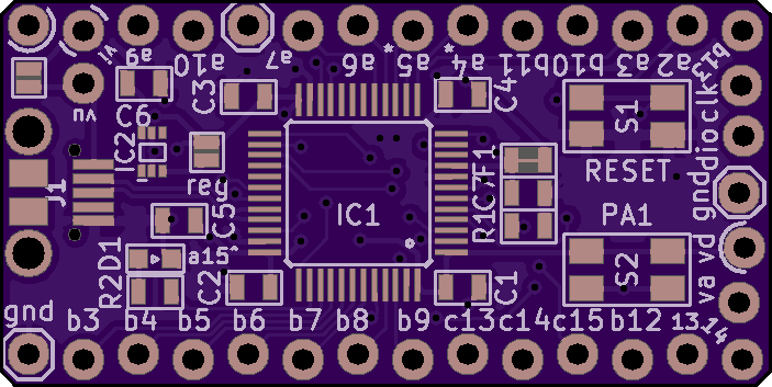
Actually, just today I've finished another STM32 breakout board, but it still doesn't satisfy matt3o's requirements (it is one sided but wrong position of the micro USB, buttons are slightly taller than USB, only 26 pins, and it's teensy 3.2-sized). You might just as well use a Teensy 3.2 (which has more pins broken out on the bottom side) for a keyboard instead of this one. I had a different application in mind (very low power sensors).
-
Matt_
- Location: France
- Main keyboard: KBT Pure Pro
- Main mouse: G500
- Favorite switch: MX Red, MX Blue
- DT Pro Member: -
That would be a great idea. I was playing with a custom AT32u4-based controller project that I could use on different PCBs a few weeks ago, but with a single row of pads: https://geekhack.org/index.php?topic=48 ... msg2050620
I love the flexibility that such a controller would provide, so I'll be following this thread with interest.
edit : Flabbergast, I like the staggered pads on your board. Are they meant to allow pads to make contact with headers without soldering?
I love the flexibility that such a controller would provide, so I'll be following this thread with interest.
edit : Flabbergast, I like the staggered pads on your board. Are they meant to allow pads to make contact with headers without soldering?
-
flabbergast
- Location: Southampton, UK
- DT Pro Member: 0120
- Contact:
@Matt_: yes, the staggered holes hold a row of pins pretty tightly. Great for testing. The idea is from mchck (I think originally from SparkFun though.)
Coming back to what I wrote (... QFP impossible ... bla bla ...) It may be possible to do, but it will be _very_ tight. {On the other hand, the only reason to go with QFP instead of QFN is hand-solderability, and that would also require other parts to be hand-solderable, i.e. at least 0603... _veeeery_ tight, but perhaps possible. LQFP-48 max. Close to mchck.}
Coming back to what I wrote (... QFP impossible ... bla bla ...) It may be possible to do, but it will be _very_ tight. {On the other hand, the only reason to go with QFP instead of QFN is hand-solderability, and that would also require other parts to be hand-solderable, i.e. at least 0603... _veeeery_ tight, but perhaps possible. LQFP-48 max. Close to mchck.}
-
vvp
- Main keyboard: Katy/K84CS
- Main mouse: symetric 5-buttons + wheel
- Favorite switch: Cherry MX
- DT Pro Member: -
Good point about voltage regulator.
So that would mean some Kinetis chip. What do you mean a bit out of spec? Do they not officially support USB without crystal?
If it is supposed to be factory produced then QFP is a bad choice. Is preloaded boot loader on the chip important in this case? I mean how expensive it is to add it at the factory?
-
matt3o
- -[°_°]-
- Location: Italy
- Main keyboard: WhiteFox
- Main mouse: Anywhere MX
- Favorite switch: Anything, really
- DT Pro Member: 0030
- Contact:
Just to be clear, my specs are just suggestions not actual requirements. Let me expand my rationale a bit.
- TMK compatibility would be mandatory, and I mean without hacks. Every time the firmware is updated it must be just a matter of recompiling. As far as I understand atmega32u4 and few others have this flexibility even though more chips seem to be supported.
- 38x18mm is approximately the clearance that we have available between the stabilizer and the switch of a 6.25u spacebar. For small keyboards with a sandwich case that would be the perfect spot for the controller. Of course all components and ports must fit, so I'm not sure what the final size will be, you tell me
- components on one side as I already mentioned it is to be able to place the board flush over a PCB (or anywhere). That also seems to help the development phase (as flabbergast says) and probably reduce cost.
- micro usb or usb-c it's just to keep the board as thin as possible. You usually put the controller horizontally inside your keyboard, so it makes sense that the port is on the longer side facing up.
- access to the usb pins, this is for easy routing in case you need to make an extension cable inside the keyboard from the controller to the keyboard side.
- screws well having the possibility to fix the board somewhere is always nice
The idea is to have the board produced and assembled in a factory, so we can go pretty crazy with the design, of course the smaller the traces/components the fewer the factories that could work on it.
-
flabbergast
- Location: Southampton, UK
- DT Pro Member: 0120
- Contact:
@vvp - USB on Kinetises: out of K20x and KL2x only KL27 officially supports crystal-less USB.
TMK on STM32 and Kinetis - not sure what do you mean "without hacks". At this point you get the official TMK sources, get the official chibios sources (it's 2 repos for Kinetis), an ARM toolchain (the analogue of avr-gcc for ARM chips) and run 'make'. {The updates have been accepted to both TMK and chibios.}
Screw holes are nice but they cost a lot of PCB space.
-
matt3o
- -[°_°]-
- Location: Italy
- Main keyboard: WhiteFox
- Main mouse: Anywhere MX
- Favorite switch: Anything, really
- DT Pro Member: 0030
- Contact:
as long as things don't break when TMK is updated, I'm fine with thatflabbergast wrote: ↑TMK on STM32 and Kinetis - not sure what do you mean "without hacks". At this point you get the official TMK sources, get the official chibios sources (it's 2 repos for Kinetis), an ARM toolchain (the analogue of avr-gcc for ARM chips) and run 'make'. {The updates have been accepted to both TMK and chibios.}
-
vvp
- Main keyboard: Katy/K84CS
- Main mouse: symetric 5-buttons + wheel
- Favorite switch: Cherry MX
- DT Pro Member: -
Still KL27 looks quite nice. Do you know how the boot loader selects the source. Will it just use the first peripheral (from UART, SPI, I2C, USB) on which it detects activity?
-
Matt_
- Location: France
- Main keyboard: KBT Pure Pro
- Main mouse: G500
- Favorite switch: MX Red, MX Blue
- DT Pro Member: -
I don't get it. If the controller is meant to be placed here, why should it have a USB port? Would it not be simpler to break out the four USB lines?matt3o wrote: ↑- 38x18mm is approximately the clearance that we have available between the stabilizer and the switch of a 6.25u spacebar. For small keyboards with a sandwich case that would be the perfect spot for the controller. Of course all components and ports must fit, so I'm not sure what the final size will be, you tell me
-
DiodeHead
- Location: Spain
- Favorite switch: Gateron white
- DT Pro Member: -
vvp the link i posted it`s a k27 board and doesnt have regulator, ask flabbergast, but i think it already has it inside, that model u have it in other packages like qnf i think, but software side looks like smt32 is already fully working with TMK if what i read is right.
-
flabbergast
- Location: Southampton, UK
- DT Pro Member: 0120
- Contact:
About KL27:
- Freescale f**ked up part numbering again, there are 2 kinds of KL27: MKL27Zxxx (where xxx is either 128 or 256) - these have an internal regulator, so can run off of USB directly. The other kind is MKL27Zxx (xx = 32 or 64), these don't have a regulator.
- bootloader: there is an option byte which selects whether to boot from flash or ROM (this is set in the firmware). If you want the bootloader at least sometimes, you need to select boot from ROM (=bootloader). If this is set, the MCU determines whether to continue with a bootloader or jump to firmware by checking the state of a particular pin ( - that's why my breakout has 2 buttons: pressing one during powerup or reset brings up the bootloader). AFAIK there is no hardware way of getting the behaviour that we're used to on atmega32u4 (i.e. powerup => firmware, reset => bootloader), but of course this can be done in the firmware (i.e. firmware runs every time, checks the reason for reset, and if it's not a power-up then jumps to the bootloader).
- more about the USB bootloader: the one that is in KL27 actually implements a vendor HID device, (so no drivers are needed), but then it requires to download an application for flashing (from Freescale, for free). {The protocol is open and documented.} {It is also slower than DFU.}
- about the other options (I2C, SPI, UART) I haven't tried those. There is an option byte that allows enabling or disabling the protocols; I would imagine that by default they're all on, and the bootloader just waits on all those if there's any activity.
- there are some quirks of KL27 that are not fully documented in the datasheet (e.g. I2C driver needs a workaround {present now in chibios already}), a reset from bootloader brings up the bootloader again for 5 seconds regardless of the option byte setting). But so far nothing that would prevent this from being used for a keyboard.
By the way: if you guys would want a mass storage bootloader (i'm not a big fan of those, but people seem to be excited about them) then we can use pretty much any MCU (except ARM Cortex M0; M0+ is OK) and code one ourselves (actually maybe haata already has one for Kinetis K20x; and there's one in LUFA for ATMEL devices).
-
flabbergast
- Location: Southampton, UK
- DT Pro Member: 0120
- Contact:
If we go the ARM way, I would go for KL27 in QFN48 package (enough pins, 8 extra passive parts + LEDs/buttons, no factory flashing required and we can put another bootloader on it if we want) or MK20 in either QFN48 or LQFP48 (same as KL27 but factory flashing or a hardware programmer required, a bit out-of-spec - but thoroughly tested chip (Teensy 3.0, mchck, infinity keyboard)).
{STM32, while I like them, seem to mostly not come in QFN packages. Otherwise STM32F0 or STM32L0 have crystal-less USB, require extra 7 passive parts + 1 IC (regulator), but stuck with DFU bootloader on F0 and only UART bootloader on L0 (but can flash a custom one with just an USB-to-serial converter).}
{For comparison, atmega32u4 requires at least 9 passive parts + crystal.}