I was under the impression that this is to be assembled in a factory.bpiphany wrote: ↑My God, you're on page 12 already.. I haven't read it all.
All I have to say is that QFN's are a bitch to solder at home. At least quickly and reliable. There may be people with more assembly skills than me out there, but I tend to get a lot of solder bridges, or unconnected pads, always requiring hands on touching up. And that is no fun at all, not even seeing the pads and all.. 0402s and other fine pitched things are ok, they are at least accessible. I have a hard time believing anyone will want to be home-assembling something like this for the masses. Factory assembled is another story of course.
Can we design the teensy alternative for keyboards?
-
pomk
- Location: Finland
- Main keyboard: ergoDox
- Main mouse: zowie ec2
- Favorite switch: brown
- DT Pro Member: -
-
matt3o

- -[°_°]-
- Location: Italy
- Main keyboard: WhiteFox
- Main mouse: Anywhere MX
- Favorite switch: Anything, really
- DT Pro Member: 0030
- Contact:
yes these boards will be factory assembled.
-
hasu

- Location: Japan
- Main keyboard: HHKB
- Main mouse: HHKB
- Favorite switch: Topre
- DT Pro Member: -
Hi all,
Great job, and thank you for useful information.
I have checked this thread periodically but not sure I can follow current status of this project. I'm interested mainly in bootloader and solution for programming in user site. I won't be a user of this alternative board but like to use compatible setup in my future project.
I got QFN32 of KL27Z256 the other day and played with its bootloader on breadboard for a few days. Kinetis ROM bootloader(KBOOT) is very powerful and you can even recovery from infamous 'FSEC' trap('secured' chip state). But it is too powerful and you can easily shoot yourself in the foot, that is, you can change boot sequence config with writing FOPT(and FSEC) bytes accidentaly and lose access to bootloader. You cannot recover it from the situation without SWD adapter such as J-Link or CMSIS-DAP. In fact I am idiot and wrote wrong file into the chip without careful thought and bricked my controller several times
Is there safe way for average users to use KBOOT? I hope the controller provides configuration for fool-proof programming operation. Or as flabbergast said, we need other safe bootloader than KBOOT?
flabbergast wrote: ↑ Couple of comments:
- it's impossible to achieve the "AVR behaviour" (one button => bootloader) hardware-wise with this chip (or actually with any ARM chip I've looked at, i.e. STM32, Kinetis, LPC), without some cooperation of the firmware.
- another advantage of having our own bootloader is also to prevent the users from accidentally bricking their chip. The Kinetises have a security option byte at 0x40c, and writing a wrong value there will 'lock' the chip; it's possible to 'lock' it so that it's impossible to change *or erase* the firmware at all. If we write our own bootloader, this can't happen (that address can be/is within the bootloader itself).
EDIT: Forgot to say that it will be relatively easy to make Jacob's kiibohd bootloader run on this, so having a DFU bootloader will definitely not be a problem.
-
tigpha
- Location: United Kingdom
- Main keyboard: IBM Bigfoot + Arduino
- Main mouse: Kensington Orbit Trackball
- Favorite switch: IBM Model F buckling spring
- DT Pro Member: -
Hasu, I notice you wrote a comment on the Anyone interested in an ADC-based capsense controller? thread. Do you know if the chip proposed here is capable of capacitive sensing, or CapSense® as Cypress Semiconductors insist on calling it? I'd love to see this project offer support for IBM Model F, and other capacitive keyboards, and possibly (why not?) also magnetic valve ones.
-
flabbergast

- Location: Southampton, UK
- DT Pro Member: 0120
- Contact:
The proposed chip (MKL27Z256*) does not have any special capacitive sensing hardware module (this is really very similar chip as the one in Teensy LC). {The K20 family, think Teensy 3.x/MCHCK/InputClubKeyboard, does have *a* capsense module, the hardware module is called TSI.} {So any capacitive sensing would have to be done in firmware - which is possible, as various libraries for Teensies demonstrate.}
@hasu: the KBOOT bootloader is open source {maybe also the host app?}, so I think that if we go that way, we should provide our own 'host application' which would make sure that the wrong values aren't written to the FSEC/FOPT bytes.
{EDIT: What I mean to say is that the bootloader running on the chip does not do any special protection, by design - the point is that some companies/uses may want to flash a 'protected' firmware using this bootloader. However the host app can of course decide what data it's going to send to the MCU bootloader.}
Last edited by flabbergast on 31 May 2016, 09:12, edited 1 time in total.
-
hasu
- Location: Japan
- Main keyboard: HHKB
- Main mouse: HHKB
- Favorite switch: Topre
- DT Pro Member: -
tigpha, as two guys above said, it is possible to implement capacitive sensing on the chip. but you may need some extra capacitors and resisters. Every controller with ADC or comparator can be used, methink.
flabbergast, ah, custom host app is nice idea and good enough for us among the community. I still wonder if Freescale provides method letting end-users use ROM bootloader in safe way, if not it surprises me a bit.
flabbergast, ah, custom host app is nice idea and good enough for us among the community. I still wonder if Freescale provides method letting end-users use ROM bootloader in safe way, if not it surprises me a bit.
-
Ratfink

- Location: North Carolina, USA
- Main keyboard: IBM Displaywriter
- Main mouse: CST L-Trac
- Favorite switch: Beam Spring
- DT Pro Member: -
Since there seems to be some concern about ARM MCUs having bootloaders that don't do what we want, I'd just like to point out that NXP's LPC11U6x series might be perfect for this job. It has built-in USB, and if the ISP line is held low on reset and a USB-select pin is held high, it runs a bootloader that allows programming by USB flash drive emulation. If the USB-select line is wired on the board, all that needs to be done to enter the bootloader is hold one button while plugging in the USB cable.
-
flabbergast
- Location: Southampton, UK
- DT Pro Member: 0120
- Contact:
There are a few reasons I prefer Freescale (well it's also NXP now) Kinetis to LPC chips: LPC chips need both a crystal AND a voltage regulator; Jacob's (aka kiibohd) code is for Kinetis ("bare-metal", so portable to other Kinetis chips without too much work, but other families require quite a bit of work); TMK with chibios backend also does not support these LPCs (although the mbed backend does).
As you say, they do have the advantage that the default bootloader in ROM is a mass storage one.
EDIT: I see now that LPC11U6x can do low-speed USB without a crystal. So not sure that the mass storage bootloader works without a crystal.
As you say, they do have the advantage that the default bootloader in ROM is a mass storage one.
EDIT: I see now that LPC11U6x can do low-speed USB without a crystal. So not sure that the mass storage bootloader works without a crystal.
-
Ratfink
- Location: North Carolina, USA
- Main keyboard: IBM Displaywriter
- Main mouse: CST L-Trac
- Favorite switch: Beam Spring
- DT Pro Member: -
I just checked because I wasn't sure, and it turns out that it does need a 12 MHz crystal for the USB bootloader to work. Given how tiny this board has to be, I can see how requiring three additional components may be a dealbreaker.
By the way, I don't think I've seen any design with castellated pads in this thread, which I find a bit odd. We're trying to make it so this board can be soldered flat against another PCB for Ridiculously Thin Keyboards®, but header pins are required?
By the way, I don't think I've seen any design with castellated pads in this thread, which I find a bit odd. We're trying to make it so this board can be soldered flat against another PCB for Ridiculously Thin Keyboards®, but header pins are required?
-
matt3o
- -[°_°]-
- Location: Italy
- Main keyboard: WhiteFox
- Main mouse: Anywhere MX
- Favorite switch: Anything, really
- DT Pro Member: 0030
- Contact:
if possible I would totally like to have a castellated PCB along with the standard hole pads
-
flabbergast
- Location: Southampton, UK
- DT Pro Member: 0120
- Contact:
IO: as many as we can. ISP: depends on the architecture (it is 4 for AVRs: reset, miso, mosi, clk; but only 2 for ARMs: SWDIO, SWCLK). I personally would like to see at least one more power pin, "VIN", plus a bunch of solder jumpers.
Once more about the power: 4 pins altogether: GND, VUSB, VIN, VCC. About the nets:
- VUSB: connected to USB's 5V
- VIN: connected to the input of the regulator
- VCC: connected to the power pins of the MCU
The most standard operation is when VUSB is connected to VIN, and the output of the regulator is connected to VCC (i.e. USB powered). There are two more situations that I'd like to support:
- Rechargeable battery powered: In this case: VUSB is connected to the input of a charger, VIN is connected to the battery output, and VCC is connected to the output of the regulator. (So the thing runs on battery, the voltage is regulated, the battery is being charged when the USB is plugged in.) This setup needs the solder jumper between VUSB and VIN to be disconnected.
- Powered directly from a battery (3V - 3.6V, e.g. 2 AA batteries). In this case: VUSB is connected to VIN, the regulator output is not connected to anything, and the battery output is connected to VCC. This setup needs the solder jumper between the regulator output and VCC to be disconnected.
It's a bit complicated, so here's a diagram:
(SJ = solder jumper, < ... > is a physical part, | ... | should be an accessible pad.)
EDIT: the power considerations above apply to ARM chips (which run on 3.3V), for 5V running AVRs we only need VUSB, VIN and a solder jumper between those. Running on batteries will require some soldering in some diodes.
Once more about the power: 4 pins altogether: GND, VUSB, VIN, VCC. About the nets:
- VUSB: connected to USB's 5V
- VIN: connected to the input of the regulator
- VCC: connected to the power pins of the MCU
The most standard operation is when VUSB is connected to VIN, and the output of the regulator is connected to VCC (i.e. USB powered). There are two more situations that I'd like to support:
- Rechargeable battery powered: In this case: VUSB is connected to the input of a charger, VIN is connected to the battery output, and VCC is connected to the output of the regulator. (So the thing runs on battery, the voltage is regulated, the battery is being charged when the USB is plugged in.) This setup needs the solder jumper between VUSB and VIN to be disconnected.
- Powered directly from a battery (3V - 3.6V, e.g. 2 AA batteries). In this case: VUSB is connected to VIN, the regulator output is not connected to anything, and the battery output is connected to VCC. This setup needs the solder jumper between the regulator output and VCC to be disconnected.
It's a bit complicated, so here's a diagram:
Code: Select all
USB 5V ---| VUSB |---( SJ1 )---| VIN |---<in VoltReg out>---( SJ2 )---| VCC |---<in MCU>
EDIT: the power considerations above apply to ARM chips (which run on 3.3V), for 5V running AVRs we only need VUSB, VIN and a solder jumper between those. Running on batteries will require some soldering in some diodes.
-
flabbergast
- Location: Southampton, UK
- DT Pro Member: 0120
- Contact:
Didn't know about that - any reference?pomk wrote: ↑The (arm) MCU is not designed to be powered from 2x AA as it can only use about 20% of the batteries full capacity, thus I would not design any features around it.
The 2xAA was only an example, it could be any power source producing reasonably stable 1.8V to 3.6V. For instance a step up converter from 1 AA, or a more efficient voltage regulator than the one in the MCU.

-
flabbergast
- Location: Southampton, UK
- DT Pro Member: 0120
- Contact:
Thanks, I understand now. My mistake, I said min 3V above. Every ARM chip can do that, but the actual minimum depends. For the MCU we're considering (MKL27Zxxx) it's 1.71V according to the datasheet. This normally means it can usually go a bit lower, but it becomes unpredictable.
-
pomk
- Location: Finland
- Main keyboard: ergoDox
- Main mouse: zowie ec2
- Favorite switch: brown
- DT Pro Member: -
My mistake for not checking the datasheet. If the limit was 3,0-3,6V as stated in the earlier post, then my assumption would have made sense. If the limit is 1,71-3,6V then it most definitely can utilize alkaline batteries without problems.
-
bpiphany
- Location: Stockhom, Sweden
- Main keyboard: Symmetric Stagger Board
- Main mouse: Kinzu
- Favorite switch: Topre
- DT Pro Member: -
How does the price for assembly differ between QFN vs. parts with leads? When I was looking around some time ago. QFN and 0402 seemed much pricier than the next step larger.
What are the arguments moving to ARM? Are they cheaper, smaller, newer, more powerful, running on lower power?
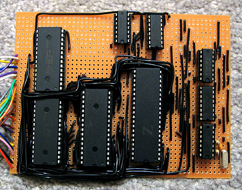
I'm obviously a fan of decoders/multiplexers. They could even be moved away from the controller board completely. It does make some sense spreading them out over the main board to reduce the number of traces needed to be routed to the controller itself. Decoders come in all sorts of easily soldered packages. Using decoders moves a bit further away from the Teensy concept, with all GPIO pins, but on the other hand this is supposed to be something keyboard specific.
For what it's worth. Here it is, my latest masochistic mistake...
It does work, and with more practice assembly may be a smoother experience. I made more bad decisions on the board it goes onto, but those should be possible to correct. This one is a bit beat up from endless touching up...
Does anyone know if there are test clips like this with 1mm pitch? I should have known to stick with something imperial =P
What are the arguments moving to ARM? Are they cheaper, smaller, newer, more powerful, running on lower power?
I'm obviously a fan of decoders/multiplexers. They could even be moved away from the controller board completely. It does make some sense spreading them out over the main board to reduce the number of traces needed to be routed to the controller itself. Decoders come in all sorts of easily soldered packages. Using decoders moves a bit further away from the Teensy concept, with all GPIO pins, but on the other hand this is supposed to be something keyboard specific.
For what it's worth. Here it is, my latest masochistic mistake...
- nucleus_small.jpg (552.81 KiB) Viewed 6966 times
- paw2016.jpg (289.28 KiB) Viewed 6966 times
- clip.jpg (27.67 KiB) Viewed 6966 times
-
flabbergast
- Location: Southampton, UK
- DT Pro Member: 0120
- Contact:
The MCU we're considering at the moment (MKL27Z256*), the main reason for QFN is space. The various packages are priced about the same (with QFN slightly cheaper), but the smallest package with leads on that one is LQFP-64. Which is big.
For me the most compelling reason for ARMs is the hardware debugging (it is soooo much easier to step through the code as it runs on the MCU than putting blinks and serial outputs everywhere to get a clue about what's actually going on). Of course this probably doesn't matter for most people (who are not actually writing firmware code
Other than this: 28kB limit on AVR (yes, there are at90usb*, but they are much more expensive and, again, bigger packages), smaller number of external parts, and, to a lesser extent, speed.
Multiplexers: that's probably a way to go for bigger keyboards, but since we have the GPIOs, the challenge so far was to do a small board with as many GPIOs on pads as we can. I strongly advocated for 2.54mm pads, to make it reasonably directly solderable for the newbies.
BTW I remembered now that the Chinese already have an atmega32u4 board, flat solderable onto a bigger PCB, with (I think) 1.27mm pads: Kimera Core. While great for a PCB project, I wouldn't want to solder wires to these pads directly. Solder bridges and cold joints galore...

-
Halvar

- Location: Baden, DE
- Main keyboard: IBM Model M SSK / Filco MT 2
- Favorite switch: Beam & buckling spring, Monterey, MX Brown
- DT Pro Member: 0051
I tried to get a Teensy 2.0 from a guy selling Teensies and other breakout boards at the Make Munich trade show this spring, and the guy looked at me like I had asked for a Z80. Good thing he couldn't see the keyboard I needed it for...
-
elecplus

- Location: Kerrville, TX, USA
- DT Pro Member: 0082
- Contact:
You mean one similar to this one?Halvar wrote: ↑I tried to get a Teensy 2.0 from a guy selling Teensies and other breakout boards at the Make Munich trade show this spring, and the guy looked at me like I had asked for a Z80. Good thing he couldn't see the keyboard I needed it for...
- IMG_5295.JPG (570.47 KiB) Viewed 6892 times
-
matt3o
- -[°_°]-
- Location: Italy
- Main keyboard: WhiteFox
- Main mouse: Anywhere MX
- Favorite switch: Anything, really
- DT Pro Member: 0030
- Contact:
more like this
-
matt3o
- -[°_°]-
- Location: Italy
- Main keyboard: WhiteFox
- Main mouse: Anywhere MX
- Favorite switch: Anything, really
- DT Pro Member: 0030
- Contact:
don't give up on me!
as I said, I'm available at paying for the design! of course the final cost will be a tad higher, but better than not having it at all
as I said, I'm available at paying for the design! of course the final cost will be a tad higher, but better than not having it at all
-
mohitgarg
- Main mouse: R.A.T 7
- Favorite switch: Blue
- DT Pro Member: -
Haven't given up, just extremely exhausted from work for the past few weeks. (You'd have seen a trend, as soon as I flew from ohannesburg to India, I've been super busy)
Also, still no consensus on microUSB+1.6mm PCB vs USB Type-C+1.2mm PCB?
Also, still no consensus on microUSB+1.6mm PCB vs USB Type-C+1.2mm PCB?
-
matt3o
- -[°_°]-
- Location: Italy
- Main keyboard: WhiteFox
- Main mouse: Anywhere MX
- Favorite switch: Anything, really
- DT Pro Member: 0030
- Contact:
honestly depends mostly on pricing