Man vs MicroSwitch: Converting a SD16234

User avatar
LessthanZero

27 Aug 2018, 00:56

openpicflipped.jpg
openpicflipped.jpg (3.08 MiB) Viewed 49219 times
The Space Cadet was something that was talked about in hushed voices in my high school computer group as if its name were holy and to speak the word at a normal volume would be sacrilege. I can still remember fantasizing about owning one, about writing programs with one. I suppose it's the sort of thought a young athlete might have,
``Gosh if I could just get those Nike Pumps I know I could dunk.''

I was doomed to eternal suffering it seemed until one day quite by chance I noticed a video recommendation while I was searching for some Slime tutorials. This video had a maniac on the screen with an actual Space Cadet keyboard and he had a voice like Barry White it was one of the most amazing things that I had ever seen. The only problem it seemed was that it hadn't been converted to work with a modern computer, he couldn't use the damn thing. It was a shame that it was nothing but a shelf queen. I had dreamed of typing on the Space Cadet, not staring at it through a display case.

If I could never have a Space Cadet and I had long ago accepted that fact. (Yeah I called Symbollics, yeah I'm on their stupid waiting list.)

If I couldn't have the real deal, then surely I could have the next best thing. I could make a replica. Now I knew I could go the cheap(cheaper) way and just use Cherry or Matias and try to re-purpose some already made kit and maybe order some Caps from Signature Plastics. But I thought if I was going to do it, I might as well do it as perfectly as I could. I decided that would at least be a keyboard made with the same switches and preferably on the same type of PCB with an identical housing made from identical materials. Keycaps could be made, but preferably I could find enough donor boards and mix and match.

I knew this would be expensive and require a good amount of work on my part but I'm a hacker and I could smell the beginning of a project brewing. As any good hacker would, I dove in head first at full speed.

That said once I began my research into MicroSwitch the Wiki was my primary source of information so I have to give a huge thank you to the people that are responsible for writing the articles and posting the links. The SD16 documentation was priceless. I also need to thank MMcm(Mike McMahon), who I don't know and have never had any contact with. His code gave me a good jumping off point and made my conversion possible. I really also need to thank DorkVader, XMIT, and all the others on the boards who had already broken this ground a bit before I trod on it. Of course another thanks to the admins of this site for keeping it all going in the first place.

Enough chit chat...

The four pin has an output and an input, the input is an enable pin. Here is the relevant quote

`` The modules output signal is valid when the input interrogation signal(clock pulse) is low and the key is depressed.''

When I read this paragraph I instantly knew I could have full n-key rollover with these switches, they were designed for it.


This is for all four pin SD-16 switches as far as I know, the switches output is variable though I believe some switches hold open while others emit a pulse. There might be other types but the documentation we have doesn't mention them so I can't say one way or the other. But all of the four pin switches have an enable that when high inhibits output.


----------------------------
| Four Pin | Three Pin |
|____________|_____________|
| ground pin | Ground Pin* |
| output pin | Output Pin |
| enable pin | Power Pin |
| power pin | |
----------------------------

The three pin SD type is I believe an early example of some of the more modern low power Hall Effect transducers that are currently on the market.
The three pin has two modes of operation. It can operate in a normal level sourcing mode with a power, ground, and an output (pin). When used in this manner the switch works just like any four pin sans enable. To operate in what is termed 'Scanned Mode' the ground pin becomes the negative supply and is used as an enable. Applying current to the negative (ground) pin starves the switch putting it into an off state. When the current is removed the switch can draw power and function normally. Of course if the plunger is not depressed the output remains low.

I had wanted to find a MicroSwitch board with the same type of switches that were found on the Space Cadet. But there were none to be found on ebay. So after a good two or three months I finally settled on a board that had the right qualities. Which honestly were cheapness and switch numbers that weren't of the pulse variety.

At the time I tried to get switches that were of the logic scan signal type on the Wiki switch listing but I really think that all the four pin SD16 switches are logic scan signal output. We only need to differentiate between pulse and hold. (Note: This is my personal conjecture and I can't verify this I only have a few switch types.)

I felt like a hacker again, I dove in as any good hacker would headfirst and with full abandon. My wife thought I was crazy. I had spent over a hundred dollars getting the keyboard and a Teensy with headers. Luckily, I already had breadboards and a Fluke Multimeter but no O-scope or any other high tech diagnostics. I honestly didn't know enough to even know if I needed all of that stuff.

I made a power supply out of a cell phone charger that output 5v and began printing out all the documentation that I could dig up about the SD series and Honeywell in general, which is very sparse. There is no home of MicroSwitch keyboards like you have with IBM or SGI and the Wiki has just about everything that has been gathered about these interesting switches.

After a few days of waiting it arrived and I had planned on using some of my vacation from work to devote all my time to working on the project. I wanted to give something back to the community that had helped me so many times when I needed to identify a board or when I was trying to determine if a switch was authentic or a clone.

I wanted people everywhere to be able to use these old MicroSwitch boards. The feel of those keycaps and the dream of having something that sexy on my desk was also a big factor.

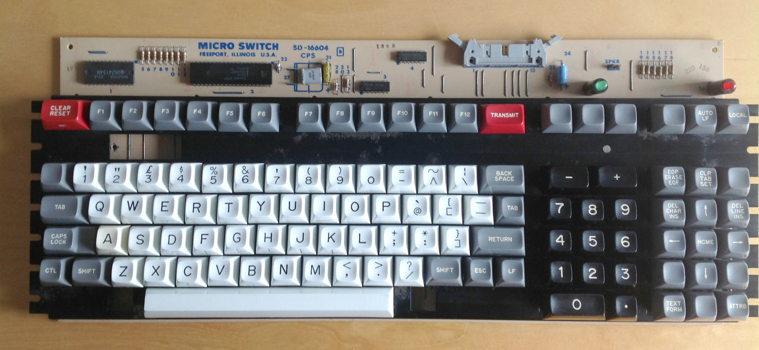
When I opened the box this is what I saw,
establishingkeycaps1.jpg
establishingkeycaps1.jpg (3.74 MiB) Viewed 49219 times
When I depressed a plunger it slipped down with all its promised smoothness, this is the closest you can get to touching an angel I remember thinking. The deep clunk of the switch bottoming out was satisfying (something I always do on linear switches). I can honestly say it was one of the few times that I felt that the hype was justified.

This is what she looks like naked, I love the modular mounting system that would allow for awesome customization as far as I can tell there is no reason why you couldn't turn this into a Space Cadet type. I would just need to get more switches and have a keycap set made or just accept having a motley assortment of keys.
naked1.jpg
naked1.jpg (4.22 MiB) Viewed 49219 times

After carefully going over the board, I began to write down the part numbers for the different chips that had been placed on the upper edge of the PCB. A few of the chips didn't have anything to do with the actual operation of the keyboard, such as an optical driver for a light pen.

I used the datasheet of the TI 74154, which is a four to sixteen line demultiplexer to determine where the power and ground lines were, double checking myself against the big caps just below the original cable connector to be sure. I had soldered some female connectors onto a cell phone charger and I used this as my test power supply feeding the board with five volts dc.

I had already used the Multimeter's continuity tester and I really can't stress enough how much trouble and time it saved me. I think you can get away without having an O-scope but you can't get away without having a good Multimeter with a continuity tester(The louder the beep the better). Such a tester lets you with no power supplied to the board, place a probe tip on say a leg of an IC while placing the other on the connector pins to see how the connector is laid out.

Then using my Multimeter, I checked the eight test points that I had deduced were tied to one of the eight rows which I realized each corresponded to one pin on the cradle that had held an Intel 8748. I felt at this point I was making progress.

But my probes showed that there was zero volts on the test points with FIve volts supplied to the board. I checked various points on the board and found that they all had power. I asked my wife to press down keys so I could hold the probes steady on each of the test points in turn which I hoped would produce a voltage when depressed, still nothing.

Feeling defeated I went back to the SD Keyswitch document and found that someone had scribbled a diagram of a four pin hall effect, they had even labelled the pins correctly and I could clearly see that one of the pins was an input.

In a flash of insight I reached for a jumper and applied a voltage to one of the inputs on the de-multiplexor and once again probed the testpoints but was disappointed yet again.

So I rechecked the 74154's datasheet, combing through the short document. I laughed aloud when I realized my error. There were two enable pins on this chip, one had already been tied low but the other had a trace to a pin on the 8748. So running another jumper from it to ground, I tried again.

Powering up the board I used a jumper and applied a voltage to a single input on the 74154. My probe quickly found voltage on one of the rows and when I depressed a key the current disappeared. I released the switch and the current returned, if I were an athletic man I would have done a back-flip.

Now I just needed to program some kind of driver but I really didn't know anything about creating a USB device much less an entire driver library.

So starting small I wrote a simple binary counter that worked by bit shifting a one. Then set up a while loop to strobe the enable lines one column at a time. While I scanned the other port for any lines that went from high to low.

I quickly began to view the sixteen outputs of the de-multiplexor as the columns in a standard keyboard.

So my debug program was watching for any changes as it ran through a for loop enabling an input and then checked the 8 bits I gathered from reading the D port on my Teensy. I then set up a simple if statement inside two for loops, to keep up with where I was in the array so that I could print out a number to provide my location in the keymap.

This worked off the PRJC Debug Print function and it simply said KeyHit and then spit out the hex number of where the key was in hex.

It took me a little while to get the timing worked out right. I was suprised at how quickly I could poll the switches. Now this was progress. I now had a working MicroSwitch board with inherent nkey rollover I just needed a driver.

In the end I decided on the LUFA driver and as I said earlier I used the LMkbd project as a jumping off point.

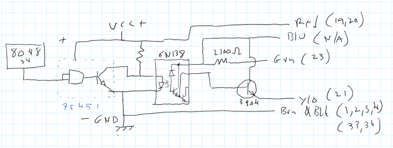
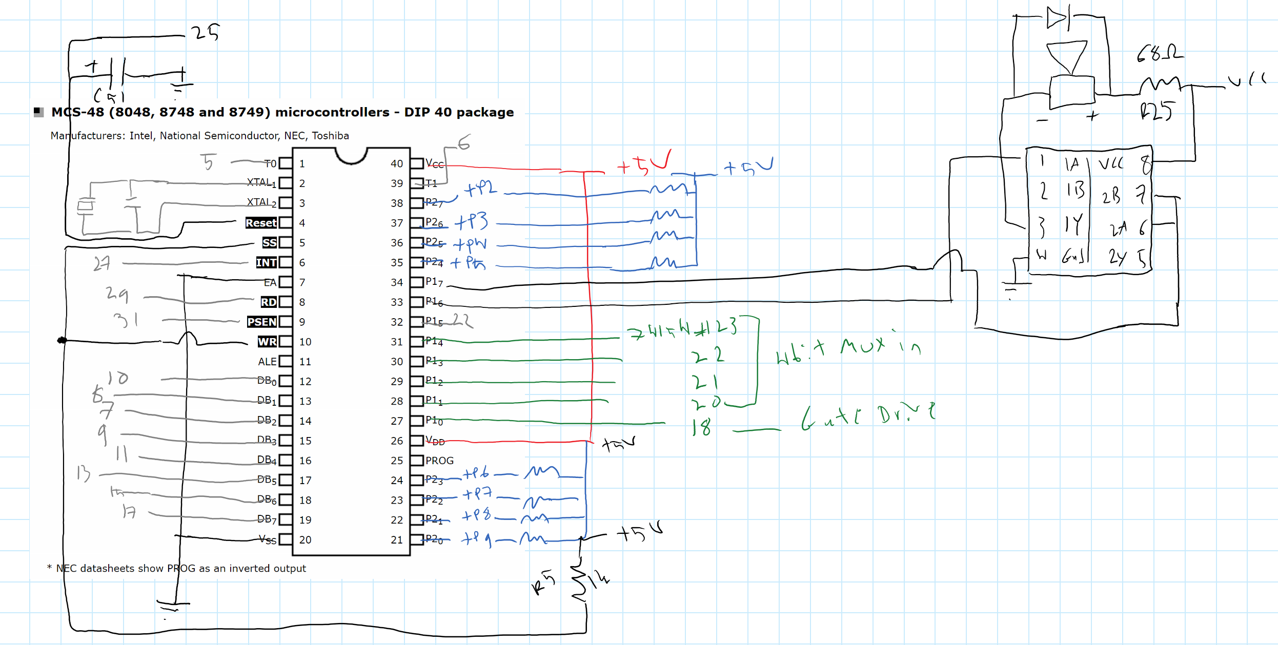
I hooked up everything with jumpers to my breadboard.

| 8748 pin | Teensy 2 pin | Signal |
|-------------|---------------|--------------|
| 20 | GND | GND |
| 40 | 5V | +5V |
| 27 | PB0 | Demux Strobe |
| 28-31 | PB4-7 | Demux Address|
| 21-24 | PD0-3 | Input |
| 35-38 | PD4-7 | Input |

Once I had the driver up and running I began the laborious process of setting up my KeyMap.

After finishing this up, I connected everything more permanently with male to female connectors. I hooked the female end to the header pins I had soldered on earlier. I then drove the male ends directly into the cradle that had already been attached to the board making sure everything was well connected. This finally brought us up to this point.
My teensy hooked into the old Micros cradle
cradlepic2.jpg (2.51 MiB) Viewed 49219 times
keypic2.jpg
keypic2.jpg (3.84 MiB) Viewed 49219 times
holdingteensy.jpg
holdingteensy.jpg (3.5 MiB) Viewed 49219 times
So now I had a working MicroSwitch. I had done it, and a part of me wanted to go brag about it, but I'm still not quite finished because there remain a few minor annoyances.

My main problem is that several keys on my board have unique shifts and I couldn't get the proper HID KeyCode for them.

This is something I've noticed on several MicroSwitch boards the open parenthesis is placed over the eight and the close parenthesis over the nine. There is no shift over the zero so this moves all the alpha-shifts one row over to the left.

There are in fact more than a few keys that are non standard and so you have to just assign them to something that's close or just use what that position would be on a standard board.
loosekeycaps.jpg
loosekeycaps.jpg (67.61 KiB) Viewed 49219 times
To me, this was unacceptable but after doing some digging I realized that there was just no easy way to make your own key shifts. There is a way, but I didn't think getting each person to patch their kernel was really going to be a popular solution.

Using the board is a little tiring. The non-standard layout drove me nuts so I messed around with the Keymap until I had the modifiers I needed for my day to day computing. With the keymap arranged properly, I started to use the board as a daily driver.

The switches are nice but heavy and tiring. They have a long travel and being linear I always bottom them out. I love the sound they make, but after fifteen minutes of typing I feel like I've been running a marathon. It's almost a piece of exercise equipment for typing strength.

The construction of the board is top notch. The PCB is thick as hell and most of the boards basic components were all military grade. It has a modular top plate that allows you to move switches around in a grid based arrangement.

Sadly I worry that we will never have a one size fits all ``Soarer'' type converter for these MicroSwitch boards. Or even a single tutorial to convert multiple board types.

HoneyWell (MicroSwitch) made mostly unique solutions to their customers specific problems. Most of the boards that I see were taken from old combined monitor, tower, and keyboard designs. These keyboards weren't designed for some protocol, they were made to work with that specific computer system which was designed in its own unique way. This creates a problem for anyone wanting to convert such a board.

Are there any XT/AT Honeywell Hall Effect boards?

I could probably come up with a way to convert most SD boards to USB or PS2 but I would have to physically work on the board and decipher it like a puzzle. Then formulate a method that would be unique for that specific board type. I'm not sure there can be one single solution.

So I have to admit that it seems the best way to go about having a modern MicroSwitch Keyboard will be designing a PCB that works with the SD type switch. It would then be trivial to use my McMM modified driver. A Kiibohd scanner module could also easily be written to work with such a PCB.

But in this idea of creating a new PCB and removing the switches from the old boards, are we not destroying something that is beautiful to create something that in all honesty will probably be less beautiful. A part of me cringes at the thought of seeing the post.

"My new old school genuine Hall Effect MicroSwitch Poker brauh."

But these switches were designed to be used and if things aren't used they have a habit of disappearing. Maybe we just need to use some discretion guys. Lets work on all the Silent 700's first. I can even draw up a KiCad project for it if no one else wants to do it.

If we come across something truly unique and truly special we should try to do a proper on board conversion to bring it back in its original state. This will be more involved, more expensive, and it might not even be possible to do in every case. But I honestly don't think destroying a work of art is worth having the coolest board on the block. That's just my humble opinion though.

Thanks
LessThanZero <0


Sidenote: I can also upload the hex and source of my code if anyone is interested because the Lmkbd source won't work out of the box, at least it didn't for me. I had to invert the logic and rewrite a few other functions. I have been working on another version based off of my Scanning function that I wrote and has a built in method for creating your Keymap.
Last edited by LessthanZero on 24 Jan 2019, 16:07, edited 1 time in total.

orihalcon

27 Aug 2018, 03:19

Very impressive writeup!

I'd love to see the source code posted and maybe a couple of brief examples of how to change the keymap. I find the most difficult part of creating a matrix is knowing exactly where a key is on the matrix. Is there some way that you could press a key, and have some sort of a listening tool that tells you the X and Y position that switch is on the matrix, so you could then go back and name the point in the matrix to what is wanted?

Also, I would find it helpful if you could make a small diagram showing how the matrix would be wired on something like a 5x4 matrix for those that are handwiring.

I've seen a few conversions on SD series which I believe only work with certain switch variants rather than based on the number of pins there are, but I definitely could be wrong with that. Would be interesting to make a table of what can and can't be converted with your firmware.

Big wish list item would be a conversion for the older SW series, not sure if your solution could be modified to work with those? I have a board that would be cool to convert, and I can probably donate you some switches if that would help at all.

Slom

27 Aug 2018, 07:10

Cool! Finally another MS conversion, congrats LessthanZero!

I'm super happy that people are working on finally dispelling that "Micro Switch are hard to convert" myth. :)
LessthanZero wrote:
The four pin has an output and an input, the input is an enable pin. Here is the relevant quote

`` The modules output signal is valid when the input interrogation signal(clock pulse) is low and the key is depressed.''

When I read this paragraph I instantly knew I could have full n-key rollover with these switches, they were designed for it.


This is for all four pin SD-16 switches as far as I know [...]
That is under the heading "Logic Scan Modules", which is the type of SD switches that this is valid for. These are those with a 'S' as last character in the part number

And, yes, I have boards where two pins are wired as output pins.
LessthanZero wrote: "My new old school genuine Hall Effect MicroSwitch Poker brauh."

But these switches were designed to be used and if things aren't used they have a habit of disappearing. Maybe we just need to use some discretion guys. Lets work on all the Silent 700's first. I can even draw up a KiCad project for it if no one else wants to do it.
Here is my TI silent, I found basically the same things you did :)
workshop-f7/converting-a-ti-silent-keyb ... 18283.html

User avatar
Muirium
µ

27 Aug 2018, 11:31

Ah, Hall effect Honeywells. How about this bad boy?

photos-f62/a-honeywell-who-dunnit-1983-t6296.html

User avatar
LessthanZero

27 Aug 2018, 14:03

Muirium wrote: Ah, Hall effect Honeywells. How about this bad boy?

photos-f62/a-honeywell-who-dunnit-1983-t6296.html

This board could use my driver with little mod it seems from the pics at least. It has the 74154 I can't tell the micro but if its an 8748 you should be good to go. Message me if you are interested in converting it and I will help you in any way that I can.

User avatar
XMIT
[ XMIT ]

27 Aug 2018, 19:49

cheapness and switch numbers that weren't of the pulse variety
Good choice. HaaTa and I still think that you can get "pulse" variety switches to behave by strobing power to them. "Hold" switches are just easier to work with.

The reason I stopped progress on workshop-f7/converting-my-wang-t12379.html was because none of the options forward were great. I could either: use the original logic to get 1KRO scanning, replace the switches, or replace the PCB with a new one that I would have to design. Maybe one day I'll come up with a good solution. I don't have the time I did three years ago for these sorts of projects.

But maybe power strobing would still work. That's the ideal approach, since it works with any kind of Hall sensor that has reliable power-on characteristics.

LessthanZero, please upload as many resources as possible (sources, schematics, built firmwares, etc.) to enable others to follow in your footsteps. I'm curious to see just what MMcM gave you. I know he's written protocol converters for other, better behaved boards than my Wang.

I have a couple of other Micro Switch boards in storage. The Wang was the prettiest of the bunch (IMO) and the one I most wanted to use as a daily driver. Maybe some of the others (like the Delta, or the TI 914) would play more nicely with this approach. I haven't tried.

okrutnik

27 Aug 2018, 23:19

Aaah this warms my heart! Congratulations.
LessthanZero wrote: I can still remember fantasizing about owning one, about writing programs with one. I suppose it's the sort of thought a young athlete might have,
``Gosh if I could just get those Nike Pumps I know I could dunk.''
...and the real Lisp hacker secret is seeping wine at your workstation :lol:
while I was searching for some Slime tutorials. This video had a maniac on the screen with an actual Space Cadet keyboard and he had a voice like Barry White it was one of the most amazing things that I had ever seen.
Care to share a link?
If I could never have a Space Cadet and I had long ago accepted that fact. (Yeah I called Symbollics, yeah I'm on their stupid waiting list.)
There still keep a waiting list, wow. Is it for whole computers?
The switches are nice but heavy and tiring. They have a long travel and being linear I always bottom them out. I love the sound they make, but after fifteen minutes of typing I feel like I've been running a marathon. It's almost a piece of exercise equipment for typing strength.
Thank you for being honest with your impressions. I thought about it today and:

1. Maybe it's like MX Blacks, which are "heavy" in a sense, but you don't actually need to press them even halfway down. You are supposed to touch them softly, pet them not hit them, and they just will register (just won't do so randomly as MX Reds do, I think). Although I am genuinely curious if someone taught people not to bottom out back in the day.

2. The software on Lisp Machines maybe wasn't meant for any kind of long typing sessions. You have mouse for object-oriented interface, and I suppose you have heavy intelligent auto-completion in Zmacs and such. It was an interactive vision of interface, just not dumbed down.

BTW it would be awesome if you tried using Symbolics Genera OS with a Space Cadetsy board, lots of people would be interested in that. The VM route is kind of shady but you know.

3. I wouldn't be surprised if they just used the most expensive parts they could get :P
But in this idea of creating a new PCB and removing the switches from the old boards, are we not destroying something that is beautiful to create something that in all honesty will probably be less beautiful. A part of me cringes at the thought of seeing the post.

"My new old school genuine Hall Effect MicroSwitch Poker brauh."

But these switches were designed to be used and if things aren't used they have a habit of disappearing. Maybe we just need to use some discretion guys.
To me it's like peasants stealing stones from ancient ruins to build their cottages. You must if you must, but it's barbaric :( I can't say anything about complex electronics stuff, but there should be ways without destroying so much, more by tasteful additions to make things usable.
Last edited by okrutnik on 16 Apr 2020, 19:57, edited 1 time in total.

User avatar
zrrion

27 Aug 2018, 23:45

You might be able to cheat with your non standard shift by making it a fn key where the layer has things moved around as necessary and has shift added to keys that need it to get capitals and whatnot.
I'm also waiting for a video showing this bad boy in action :D

User avatar
LessthanZero

28 Aug 2018, 04:21

Here is a link to the source and the Hex file which is for a Teensy 2, you can use the pinout provided if the Micro on your board matches mine, this code should work for the 3 pin SD variants as well. I say should because I have never tried it myself but I took this code almost directly from a Space Cadet Conversion that another guy named McMM had done a while back, the Space Cadet uses the 3 pin type if I'm not mistaken.
If your board has a different Micro or it has a different switch type.
I really need to get more switches so I can understand how they work. I can't understand why MicroSwitch would manufacture a Hall Effect with four pins and one of them be redundant. All the modern digital Hall Effect switches that I have found that are similar in type to the ones used in a MicroSwitch board are 3 pin. I really thought the enable pin was just something that they had done for the logic scan thing. It seems they just took an And gate and tied one leg of the Output of the transducer and ran the other leg out of the casing of the component which is a great solution to the whole n-key rollover problem.
But since I don't have any of the other signal types I really can't say much about them. But I have been looking at the the Wang Board(phrasing) I think it could be converted with just a daughter board a multiplexor and a teensy 2 but I'm an optimist(not really) But it should be possible without to much rework but I can't say without understanding fully why the switches have two pins that emit the same signal.
Here is the link to the source and hex
https://github.com/lessthan0/microswitchkbd?files=1
Last edited by LessthanZero on 28 Aug 2018, 13:13, edited 2 times in total.

User avatar
dorkvader

28 Aug 2018, 05:22

Hey cool! thanks for the PM. I have this exact KB. I only had time to skim this before bed but I'll read it in depth and have a look at maybe getting mine worked on.
This is something I've noticed on several MicroSwitch boards the open parenthesis is placed over the eight and the close parenthesis over the nine
a lot of older boards are bit paired or have layouts based on that concept. https://en.wikipedia.org/wiki/Bit-paire ... rd#Mapping
I did get the "bit paired" layout to match what's printed in the keycaps by implementing "shift' as a function key, and the "shift" function layer outputs a macro for each key that's <shift><keypress></shift>. This works to get capital letters and anything you want out of the number row. Note that bit paired keyboards also often have something weird on the 2 (usually ") and have other differences. I switched back to normal keyboarding and ignore what's printed on the number row after I got better at touch typing.
Are there any XT/AT Honeywell Hall Effect boards?
not as far as I know, but I believe you could buy one that output ASCII of some kind. Some of the apple 1 computers had one (from a TI silent 700 model 733?) http://randomvariations.com/2014/10/18/ ... ard-logic/
Lets work on all the Silent 700's first. I can even draw up a KiCad project for it if no one else wants to do it.
There's a lot of silent 700 variations. I myself have 3 that were supposedly identical, but the internals were completely different. 2 of the keyboards were the same and the third different (mostly minor layout changes and 1 layer vs 2 layer PCB). Some of the oldest Silent 700's from the early 1970's cane with the older rail mounted switches. Using the "disable' pin you can scan the matrix pretty effectively, but switches without this will be harder to adapt. When I found out my working silent 700 had 1KRO I almost despaired! then I realized that's because it's a telex unit. Adapting some of the more common silent 700's is a great next step, and I'm happy to help with versions I have.

I have a silent 700 that I have drilled the PCB and can quickly wire up any way I want, The only thing I'm missing is firmware. I'll see what I can make work.

Oh and as a "bounty" for helping me work on hall effect, I might have some extra keycaps with the legends you are after. I'll have to check through my collection though.

Finally, SP can make new hall effect compatible keycaps. You always get a few with the yearly grab-bag that they do.
this code should work for the 3 pin SD variants as well. I say should because I have never tried it myself but I took this code almost directly from a Space Cadet Conversion that another guy named McMM had done a while back, the Space Cadet uses the 3 pin type if I'm not mistaken.
I believe the 3-pin variants will power the column directly. This requires much more current (or a transistor) because the current capability of the atmega 32u4 is quite low (I think can only power 4-5 switches at a time). The current required to bring the 'output disable" pin low is very small by comparison. I used to have the results of my electrical characterization. maybe I'll re-do part of it tomorrow. Anyway it should work in a similar way, but you may run into issues if your PCB has a lot of switches in a row or your microcontroller has low current capability and you don't have transistors. Unfortunately I don't have any of the 3-pin variants to test with.

Cheers!

User avatar
Chyros

28 Aug 2018, 08:54

Wow, lots of work being done Oo .

User avatar
Sangdrax

28 Aug 2018, 10:19

This is some really great stuff. I know I'm taking notes.

User avatar
LessthanZero

28 Aug 2018, 13:52

My board is powered entirely by the USB. The space cadet was a three pin but I don't know if it has transistors on the rows. In the scanned mode you are only powering 3 or 4 switches at a time so you might not need any extra power source. I think Muirium has a board with 3 pin switches, we need to convert that board here is the link to the post
photos-f62/a-honeywell-who-dunnit-1983-t6296.html
And photo of that board
Image

User avatar
dorkvader

29 Aug 2018, 03:12

What I really like (or hate) about these hall effect boards is that they're all different. This one is an excellent example of one that looks like it was modified after the PCB was printed. I mean, look at all those capacitors on top of the pull-up resistors. Mine has a ground lead that's soldered on to the end of a trace SMD style.I have random bypass caps all on the back.

What's even more amazing is that despite being almost identical, ours are actually different. Yours does not appear to have soldermask on the top (many don't) but mine does. I can't read the printing on your demux chip (8219 is the date maybe?), but mine is actually a DM74154j by National semiconductor made in 11'th week of 1983. The PCB is also lightly different. Yours has pin 19 of the sip socket marked on the copper, that is absent at mine. Yours has two vias between the end of the sip socket and the resistors at right, mine is either routed differently or missing completely. Fortunately we aren't using the connector at the edge of the unit and I think the other routes are all the same (verifying that now). Anyway I've grabbed your HEX and a spare teensy and I'll solder it up and give it a go probably tomorrow.

Mine is also interesting because it has quite a few pad print keys (the entire function row and some others). The function row is reverse-sloped, which is relatively common on hall effect boards. See the burroughs for another example. My keycaps don't show much wear except for "send" but all the black doubleshot keycaps, the white legend has yellowed. I don't think I have any other hall effect boards with yellowed plastic.

I also really like the locking capslock, and the fact that either shift key releases shift lock. How delightful! the "bent" spacebar is (as far as I know) only used in some hall effect boards and some keytronic (I bout a want thinking it was hall effect and got duped!) also the lack of stabilizer on left shift is quirky. This is why I love these keyboards so much.

I didn't see anything in the OP, but the rest of the chips are a TI SN75451BP high current "peripheral driver interface" (for the speaker, they are only using output 1. output 1 is grounded) on the left, and on the right is an HP branded 6N138 which is an optocoupler!? (I tested it vs the datasheet and it seems to work out. Pins 1 and 4 are NC, pins 8 and 5 (vcc and gnd) are tied to the transistor next to it and go to the connector on the far right. Pins 2 and 3 (the isolated input) go through current limiting resistor 18 and to the power plane of the switches. Not sure why they needed an optocoupler for that. in 1982 this would not have been cheap. how very mysterious.

Other things to note, switches 1,2,3,25,26,27 and 21 have been desoldered at some point and flux residue is left over. I suspect whatever system these went in they modified the standard KB from microswitch pretty heavily before fitting them. Since I'm out of time for the night I'll just upload some pictures to my flickr..


Wait, I never noticed this before, but this board is identical to my texscan MSI boards!!! You can see photos of them here
https://www.flickr.com/photos/dork_vade ... 1603359937 The texscan MSI has an NEC D8048C fitted, as well as the crystal it needs and were not modified so heavily. They also have (thin) tripleshots. however the optocoupler is desoldered. I can't believe I never noticed this before. Partnumber for the texscan-specific configuration is 112SD34-1 and my examples are from 39'th week of 1983 and 38'th week. Serial numbers are 662 and 621, so microswitch was not making these frequently. edit: the "master" KB does not have the optocoupler fitted, but the "slave" kb does. Its wired up correctly also. I'm going to try and power it!

edit: texscan "slave" KB powers and draws about 300 mA at 5V. The CPU gets warm. the output has a few cables, but only appears to "read" from the transistor attached to the optocoupler, which seems to be taking its input from TP2. I'm not sure how this works and will reverse-engineer the schematic a little before I get out the scope.

User avatar
LessthanZero

29 Aug 2018, 08:24

Awesome board, man I wish I had your collection you have some really awesome stuff. Yeah all the Micro boards that I have seen are almost all different, even as you were saying boards that are of the same type. All the diferent Silent TI configurations for example or the boards like the one that I have which seems to have been made or at least modified towards a specific purpose. Like my board has caps on the back between the VCC and the Ground on several rows. I assume this was to clean up the signal for some reason maybe because they were using the CRT light pen and it was attached directly to the boards PCB. Also my board has a place for a speaker but no speaker has ever been soldered on. I can definetly tell someone other than the factory has soldered on my board there are a few caps that they left really long legs on and stuck a piece of insulation on so they could reach between pins on the IC. That's one of the reasons I really love working on these old boards because in a way its like being a detective and you are reconstructing the mind of an engineer who designed something that is truly amazing.

I fixed caps lock and the locking shift works now, I updated the git so you might want to get the latest version so you can have a fully functional board at least, I'm still working on the non standard shifts and the somewhat automated keymap generator. Hopefully your keymap will be similar enough to mine and you might not need to do much to it.

This is how I figured out my keymap, I set all the places to be a character 'o' and then I changed the first ten to the first ten letters of the alphabet. Then I compiled the code an loaded it on the teensy. Then I would depress keys until I found an A or a B whatever and I would see which Index that was in the Array and change it to the proper Keycode. For example the A might have been an X I would then change the A to an X, after I found all the keys that I could I would recompile the code and double check myself. Then I could move on to the next ten changing them from O to A through J. I just repeated this process untill I was done, after I had they keys mapped out I went back and any letter 'o' that I had left I changed to a nokey which is mapped as a 0.

User avatar
dorkvader

29 Aug 2018, 15:36

It's really odd how my two texscan MSI boards have minor differences between them. the "master" board uses the buzzer and the second output of the 75451 and does not have the optocoupler populated, whereas the "slave" board has the inputs of that 75451 channel bridged (doing nothing) and the buzzer is not soldered. This is a difference in the PCB itself. Likewise there are minor differences around the optoisolator between my SD-16234 board lessthanzero's

Anyway I reverse-engineered most of the output section and drew a partial schematic.
They have pin34 of the 8048 going into both "and" gate inputs of the 75451. This effectively acts as a buffer and gives it high current output. This then goes into the LED "input" of the optocoupler. The "output" of the optocoupler is going into a transistor and then out pin 21 of the output connector (yellow wire in the "slave texscan MSI board).

Basically, they're getting the output of pin34 on the 8048 in a fully isolated fashion, no idea why they thought this is necessary, and it's not even used on the "master" texscan board.
Image

Written data
Spoiler:

Code: Select all

75451 Dual Peripheral Driver
1	1A	bridged to 1B and not used		
2	1B	bridged to 1A and not used
3	1Y	speaker(+) & TP1 & [diode 54 -> speaker (-) & R25 pull up to Vcc]
4	GND	
5	2Y	R18 pull up to VCC & 6N138 pin2
6	2A	bridged to 2B and 8048 pin34
7	2B	bridged to 2A and 8048 pin34
8	VCC	

6N138 Optocoupler
1	NC	N/A
2	VF+	R18 pull up to VCC & 75451 pin5 (2Y)
3	VF-	GND
4	NC	N/A
5	GND	NC
6	VO	NC
7	VB	3904 base
8	VCC	blue wire -> 2100 ohm -> Green wire

3904 NPN Transistor
B	6N138 pin7 (VB)
C	Blue wire & 2100 ohm -> green wire
E	Yellow wire

kb conector
blk1	1,2,3,4	GND & momentary switch (reset?)
blk2	25	momentary switch (reset?)
blk3	33,34	GND
brn	33,34	GND
red	VCC
ylo	21	3904 emitter
grn	23	2100 ohm then blue wire
blu	n/a	3904 colector
*note* this is all for the "slave" texscan MSI boards since it has a populated 8048 microcontroller and is a self contained unit unlike the "master" texsan MSI board and the one detailed here. That said, the output will be very similar but with different pin assignments.

With all that in mind I'm going to ignore the isolated output and see what pin34 of the 8048 is doing. I'm guessing some sort of serial output, but it has to be clocked internally. In testing, the "slave" texscan board drew about 270 mA idle and about 300 mA with keys pressed. The 8041 got warm but not hot.

Awesome board, man I wish I had your collection you have some really awesome stuff. Yeah all the Micro boards that I have seen are almost all different, even as you were saying boards that are of the same type. All the diferent Silent TI configurations for example or the boards like the one that I have which seems to have been made or at least modified towards a specific purpose.
I used to think they had standard boards and then the customer (or just a regular person) could purchase them and then modify it. This board has several sections that are definitely designed to mod the output of the optocoupler, however the fact that there are physical differences to the PCB of all 4 boards seems to contradict this. They could have modified the texscan PCB from a standard part number (it only has minor mods and texscan would have bout at least 600 of them based on serial numbers) but that doesn't explain my our two boards have differences to the PCB copper (lack of soldermask is a small difference).
Like my board has caps on the back between the VCC and the Ground on several rows. I assume this was to clean up the signal for some reason maybe because they were using the CRT light pen and it was attached directly to the boards PCB.
These are decoupling capacitors, used to give the device nearby a better power signal. See here for an excellent explanation https://www.youtube.com/watch?v=BcJ6UdDx1vg
Also my board has a place for a speaker but no speaker has ever been soldered on. I can definetly tell someone other than the factory has soldered on my board there are a few caps that they left really long legs on and stuck a piece of insulation on so they could reach between pins on the IC. That's one of the reasons I really love working on these old boards because in a way its like being a detective and you are reconstructing the mind of an engineer who designed something that is truly amazing.
These boards were definitely meant to be modified by the customer, but these were modified the most out of all my hall effect boards and in such a... haphazard fashion. The soldering was all done by hand and isn't very high quality. The part selection (resistors and decoupling caps) is also somewhat random and low quality. It's all "a bit how ya goin" as they say. These wouldn't ahve been cheap parts in 1982, but I'd love to get some pricing on them.
I fixed caps lock and the locking shift works now, I updated the git so you might want to get the latest version so you can have a fully functional board at least, I'm still working on the non standard shifts and the somewhat automated keymap generator. Hopefully your keymap will be similar enough to mine and you might not need to do much to it.
That's another weird difference! the texscan boards have locking capslock to the left of spacebar, these boards have locking capslock in the top left below F1. really weird. I'll have to figure out your code to update my keymaps. Thanks for your work on this! One of my favorite features is the "shift lock" is released by pressing either shift key. It's so whimsical, I play with it all the time.
This is how I figured out my keymap, I set all the places to be a character 'o' and then I changed the first ten to the first ten letters of the alphabet. Then I compiled the code an loaded it on the teensy. Then I would depress keys until I found an A or a B whatever and I would see which Index that was in the Array and change it to the proper Keycode. For example the A might have been an X I would then change the A to an X, after I found all the keys that I could I would recompile the code and double check myself. Then I could move on to the next ten changing them from O to A through J. I just repeated this process untill I was done, after I had they keys mapped out I went back and any letter 'o' that I had left I changed to a nokey which is mapped as a 0.
That's the same way I reverse-engineer a keymap for other keyboards (like my cut-down pingsaver ibm japanese kb see here for explanation and pics https://geekhack.org/index.php?topic=85 ... msg2302188 ). I assign 1,2,3,4 etc. to random matrix positions and then press keys and match them up, then edit the keymap after. It's a lot easier for the microswitch keyboards where every key is individually numbered.

There's a lot of cool customizeable features about this board. The white jumpers (labeleed 26-41) at the far left allow tswitches 1 and 2 (first 2 switches at far left) to either be part of the normal switch matrix or wired up completely separate to the connector. The pins to the far right, which are set up for LEDs on this one you can alternatively get switches with in-switch LEDs and put the LEDs there. they are also wired up to the connector. Both of the non-texscan kbs used to have a crystal soldered but it was cut off the PCB at some point. Perhaps when the controller was removed? TP1 is for the buzzer, but TP 2-9 appear to be for the rows and are terminated with a pull-up resistor and otherwise go directly into the controller.

Despite being made only a few weeks apart (11'th week 1983 vs 21 week 1983), the texscan uses a plastic signetics 74154 and a National Semi 75451 and a nichicon input capacitor (the one at the far top right) whereas the nonbranded one uses a ceramic National semi 74154 and a texas instruments 75451 and a Nippon Chemi-con capacitor (and they have added another capacitor afterwards, also from nippon chemi). As far as I can tell, there are no major PCB differences between my "unbranded" SD16234 and the "slave" Texscan one (there's a few minor differences on the copper with regard to labelling the part number)

I do like how every component and potential jumper position is labelled. The chips are 1,2,3,4 with chip 1 (the 75451) and chip 3 (8048) are conveniently the chip number is near the specific pin of that chip.
---
ok I'm off to work. We'll see what the controller is outputting tonight!

Edit: had a look at the code, and while I don't really understand C yet (I that class is this semester!) I think I have a good idea how your keymap is working, so it should be pretty easy to remap my KB, and might not be "too" difficult to program the texscan ones with all their extra keys. Once I get it loaded and working I'll have a look at the electrical characteristics and see if those decoupling capacitors clean up the output (the raw switch output isn't great https://geekhack.org/index.php?topic=87 ... msg2355651 )

User avatar
LessthanZero

31 Aug 2018, 13:09

Just count how many possible spaces there are on the keyboard I used 128 which is just the rows and cols with keys. But I think the whole board has 6*24 or 144 possible key posistion. So just change the array size which is

Code: Select all

  static const KeyInfo Keys[128] PROGMEM = {
      
Just change 128 to 144 or whatever size you need then update the array.

Have you tried out my hex? I'm excited to see how it does in the wild.

User avatar
dorkvader

01 Sep 2018, 17:38

LessthanZero wrote: Just count how many possible spaces there are on the keyboard I used 128 which is just the rows and cols with keys. But I think the whole board has 6*24 or 144 possible key posistion. So just change the array size which is

Code: Select all

  static const KeyInfo Keys[128] PROGMEM = {
      
Just change 128 to 144 or whatever size you need then update the array.
oh ok so it scans every possible position, then you map a position to a keycode. I saw the second part of that in your code, so if I can figure out how to build a HEX from it, I'll be able to adapt my other keyboards.
LessthanZero wrote: Have you tried out my hex? I'm excited to see how it does in the wild.
Hey, the kb works great with your hex! Keys read just fine, there's basically no lag, and I count 6KRO.

but I'm having some issues with the keymap. Basically F1-F4 send weird keycodes (aquakeytest says they are bios code 0x67 windows key 0x7f for F1 for example). "Last Page" sends F5, the next key "end" is escape, they key after that and F8 do nothing, and F9-12 work great. F13-14 send "weird" keycodes and "send" is letter O. Most of the alphas are fine except the key labeled [* :] which sends letter "H" Most of the tenkey is fine except 6 sends letter "Q"

I need to head out now, but I'll double check my wiring on the inputs. It's entirely possible I have a wire crossed somewhere. I didn't have a chance to double check my wiring before my girlfriend wants to go to the county fair.

User avatar
LessthanZero

02 Sep 2018, 06:21

Awesome news awesome, I will check the source I can fix the function row I just used the standard f-alphs as placeholders while I was debuging and forgot to replace them. The switch which corresponds to 6 numpad is broken on my board so I never set it. I can update the hex in the morning I just need to find the duplicate 'Q' and 'H' then replace them with the proper keycode. Good deal, have fun at the fair.

They had some cool Microswitch numpads on ebay I don't know if he has any left but I got one and I think I'm going to make a macro pad out of it. My Silent 700 showed up today I pulled the board , I tried to take pictures of eveything so I can do a full tutorial on how to convert one to modern USB. Do we know the best way to tell that a Silent 700 for sure has hall effect switches. I just went off what the keycaps looked like

Slom

02 Sep 2018, 11:20

LessthanZero wrote: They had some cool Microswitch numpads on ebay I don't know if he has any left but I got one and I think I'm going to make a macro pad out of it.
In a repeat of history, I was faster than you *again* :p
other-external-f66/great-interesting-fi ... ml#p422963
LessthanZero wrote: My Silent 700 showed up today I pulled the board , I tried to take pictures of eveything so I can do a full tutorial on how to convert one to modern USB.
What is incomplete about my tutorial?
LessthanZero wrote: Do we know the best way to tell that a Silent 700 for sure has hall effect switches. I just went off what the keycaps looked like
Stack pole has a rounded 3 (I think),edit: the one on ebay right now has a flat top 3, dammit

clare-pendar has a completely different key cap profile.

User avatar
LessthanZero

02 Sep 2018, 19:09

My apologies Slom if I stepped on your toes but I wasn't saying that there was anything wrong with your tutorial in fact I like it. But I was planning on showing the total process from identifying the right kind of Silent 700 through removing the board and maybe adding a few more switch locations to provide a Meta and a Super, and I was thinkning of turning that left side toggle switch into a caps lock and the one on the far right could be a num lock or function layer lock key.

Did you pick up one of the keypads? I only got one of them I should have bought a few more they came with a datasheet for the SD series it was worth it to me just for that.

I want to put up a hex file that will work with the Silent 700 I know you already have an arduino version up but I was wanting to make one in C. That way it will be possible for someone who doesn't want to download the compiler to use the code. They can just grab the HEX file and be ready to go. I have no problem giving you credit though by having your name in the source for the C code since I'd base the scanner function off of your Arduino implementation.

Since there is so much variation in the design and implementation of a MicroSwitch board we are going to need to create several different conversion procedures and different driver software as well. As I'm sure you have noticed your code wouldn't work on my SD keyboard and vice versa. I will have to write a different scanner for the TI. So maybe we could have a kiibohd type of fix where people can pick the proper modules and then compile what they need.

It has been my goal with all of this to help in the creation of a single repo for MicroSwitch conversions. They are probably my favorite manufacturer, its just something about their aesthetic the beautiful double shot keycaps the thick heavy sound they make when you type in them. I even think their PCBs are sexy.
So the thought of all these wonderful keyboards sitting in silence collecting dust drove me into action, I needed to contribute I had set back for too long reaping the fruits of other mens labors. Do you have any idea how much time(and money) the Wiki and these forums have saved me. Countless times when I couldn't identify a board or if I was trying to determine if X board had Y switches before I purchased it.

I just wanted to give back and the Hall Effect thing was just where I seemed to fit in best. Although I honestly like Alps switches a little more for day to day typing. I have a silver label omnikey 102 and a fk 5001 and I love both of those boards like my children.
My other project is an attempt at cloning the blue Alps switch. I have alot of experience in injection molding and thermoforming plastics and I think that some of the problems with the other clone types could be alleviated with better quality control standards. But hey thats something I could talk about for hours. I'm about to reupload the HEX to fix the keymap as I mentioned in a earlier post. But I will wait until I hear from you before I add a C version of the Silent TI.

here is a link to Slom's tutorial on on converting the Silent 700 to work with USB
workshop-f7/converting-a-ti-silent-keyb ... 18283.html
Last edited by LessthanZero on 05 Sep 2018, 03:47, edited 1 time in total.

User avatar
LessthanZero

02 Sep 2018, 20:02

I've updated the source and HEX files fixing the keymap.

User avatar
dorkvader

03 Sep 2018, 05:43

LessthanZero wrote: Awesome news awesome, I will check the source I can fix the function row I just used the standard f-alphs as placeholders while I was debuging and forgot to replace them. The switch which corresponds to 6 numpad is broken on my board so I never set it. I can update the hex in the morning I just need to find the duplicate 'Q' and 'H' then replace them with the proper keycode. Good deal, have fun at the fair.

They had some cool Microswitch numpads on ebay I don't know if he has any left but I got one and I think I'm going to make a macro pad out of it. My Silent 700 showed up today I pulled the board , I tried to take pictures of eveything so I can do a full tutorial on how to convert one to modern USB. Do we know the best way to tell that a Silent 700 for sure has hall effect switches. I just went off what the keycaps looked like
I got a keypad from Haata back in 2011 https://geekhack.org/index.php?topic=18048.0 Here's my work so far, https://geekhack.org/index.php?topic=89262.0 but I need to know how to program to make it work. Haata has kiibohd code to set it up as a 16*1 matrix.
LessthanZero wrote: My apologies Slom if I stepped on your toes but I wasn't saying that there was anything wrong with your tutorial in fact I like it. But I was planning on showing the total process from identifying the right kind of Silent 700 through removing the board and maybe adding a few more switch locations to provide a Meta and a Super, and I was thinkning of turning that left side toggle switch into a caps lock and the one on the far right could be a num loclk to control or function layer lock key.
I plan on adding a few switch locations and maybe replacing some of the ultra-heavy switches with lighter ones. Here's a good resource for identifying various silent 700's https://terminals-wiki.org/wiki/index.php/Category:TI good rule of thumb is that things produced after about 1980 are not hall effect.
LessthanZero wrote: Did you pick up one of the keypads? I only got one of them I should have bought a few more they came with a datasheet for the SD series it was worth it to me just for that.
that datasheet is awesome. it really opened the door to starting electrical characterization of the hall effect sensors themselves.
LessthanZero wrote: I want to put up a hex file that will work with the Silent 700 I know you already have an arduino version up but I was wanting to make one in C. That way it will be possible for someone who doesn't want to download the compiler can just grab the HEX file and be ready to go. I have no problem giving you credit though by having you name in the source for the C code since I'd base the scanner function off of your Arduino implementation.
I'll also happily test it. I have 4 variations of silent 700 boards I think, but one of them is in a working 700, so it stays there. Another one I drilled the PCB so I can wire it up any way I want.
LessthanZero wrote: Since there is so much variation in the design and implementation of a MicroSwitch board we are going to need to create several different conversion procedures and different driver software as well. As I'm sure you have noticed your code wouldn't work on my board and vice versa. I will have to write a different scanner. So maybe we could have a kiibohd type of fix where people can pick the proper modules and then compile what they need.
back when I thought you had to strobe the columns (before the input-disable pin and slom method was introduced) I thought the recommended way would be to drill the PCB, then make a little hardware PCB strip to run across the top that has the requisite transistors (and probably a demux or port expander of some kind) then you'd get that, cut it to length, and put the controller on one side, then wire the rows up to it. Such a mod would work with a vast majority of PCBs.
LessthanZero wrote: It has been my goal with all of this to help in the creation of a single repo for MicroSwitch conversions. They are probably my favorite manufacturer, its just something about their aesthetic the beautiful double shot keycaps the thick heavy sound they make when you type in them. I even their PCBs are sexy. So the thought of all these wonderful keyboards sitting in silence collecting dust drove me into action, I needed to contribute I had set back for too long reaping the fruits of other mens labors. Do you have any idea how much time(and money) the Wiki and these forums have saved me. Countless times when I couldn't identify a board or if I was trying to determine if X board had Y switches before I purchased it.
and the keycaps are really unique! Your board has the "thin" doubleshots and pad print. There is one level thicher doubleshots, and tripleshots, then a super thick doubleshot and tripleshot after that! Then the spacebars are really unique, with the "bent" one and there's one with a weird profile on the long front and back that helps identfy the KB for me. Here's the pictures I have that I'll re-shoot sometime now that I have a proper macro lens. https://www.flickr.com/photos/dork_vade ... 2083935704
LessthanZero wrote: I just wanted to give back and the Hall Effect thing was just where I seemed to fit in best. Although I honestly like Alps switches a little more for day to day typing. I have a silver label omnikey 102 and a fk 5001 and I love both of those boards like my children. My other project is an attempt at cloning the blue Alps switch. I have alot of experience in injection molding and thermoforming plastics and I think that some of the problems with the other clone types could be alleviated with better quality control standards. But hey thats something I could talk about for hours. I'm about to reupload the HEX to fix the keymap as I mentioned in a earlier post. But I will wait until I hear from you before I add a C version of the Silent TI.

here is a link to Slom's tutorial on on converting the Silent 700 to work with USB
workshop-f7/converting-a-ti-silent-keyb ... 18283.html
Thanks for the link! I have a 700 like that, so I'll wire it up sometime. I remember when 700's were going for $20, I think they have gone up in price now though.
LessthanZero wrote: I've updated the source and HEX files fixing the keymap.
Awesome, I'll give it a try tomorrow.

User avatar
dorkvader

03 Sep 2018, 19:22

Still getting some errors with the layout. I think I'm going to see if I can figure out how to compile your source code into a hex file and play with the key assignments myself.

In other news I reverse-engineered the entire circuit Here's the schematic for most of it. Missing are two components that might be diodes (?) near the crystal and the output of Pin 5 of the 75451 (which is shown above). Grey are the pins on the output connector in the front. PIns 11 and 25 (ALE and PROG) on the 8041 appear to be not connected.
Image

Here's the matrix. The number in the square is the numbered switch on the back of the board. They go across then down from left to right so it's easy to see what the number is from the top. Note that switches 1-4 are wired up to the row of jumpers located at the top right called 26-41 on the PCB. These can be arbitrarily wired up. I have put them in the matrix where they are assigned on the texscan (1-3 are the same for the board here and 4 is not connected at all)

Code: Select all

		0	1	2	3	4	5	6	7	8	9	10	11	12	13	14	15
TP2	0	38	37	36	96	34	33	32	31	30	29	28	27	26	25	13	12
TP3	1	62	61	60	50	58	57	56	55	54	53	52	51	59	49	14	11
TP4	2	85	84	83	74	81	80	79	78	77	76	75	82	73	112	15	10
TP5	3	108	107	106	40	104	103	102	101	99	100	98	97	35	95	16	9
TP6	4	39	105	41	43	42	44	45	46	47	48	71	94	117	128	17	8
TP7	5	63	64	65	66	67	68	69	70	22	122	4	3	2	1	18	7
TP8	6	86	87	88	89	90	91	92	93	21	124	125	126	127	23	19	6
TP9	7	109	110	24	72	113	114	115	116	123	111	121	120	119	118	20	5
(its tab separated so it doest come out right. Paste into your text editor for a better look) I have also uploaded it here as an xlsx spreadsheet.

The columns across the top are the logical outputs of the 74154 which are labeled as 0-16 in the datasheet
The rows correspond to the inputs of the microcontroller which are also connected to test points TP2-9 and pins 35-38 and pins 21-24. In the 8048 datasheet, these are called "P20-P27" I know this doesn't apply to the board we have here, but it's very relevant to the texscan MSI boards I have as well as any other keyboard using this assembly form microswitch.

I'm still not able to get any output from mine with the 8048 microcontroller. I've traced the "issue" back to the fact that the demux output enable pin never enables the demux output, so the columns never turn on and the rows never send signals. I have a button that is connected to the "reset" pin of the 8048 but it doesn't appear to work.
Attachments
microswitch sd-16234 matrix.xlsx
(11.9 KiB) Downloaded 143 times

Slom

04 Sep 2018, 20:10

LessthanZero wrote: [...]
But I was planning on showing the total process from identifying the right kind of Silent 700 through removing the board and maybe adding a few more switch locations to provide a Meta and a Super, and I was thinkning of turning that left side toggle switch into a caps lock and the one on the far right could be a num loclk to control or function layer lock key.
That sound interesting, I'm looking forward to it :)
LessthanZero wrote: Did you pick up one of the keypads? I only got one of them I should have bought a few more they came with a datasheet for the SD series it was worth it to me just for that.
I already have one of those numpads, so I could not justify the price (shipping to europe is not free :( )

The datasheet has your answer about the modules with two outputs: "[...] the [current sinking] level modules have two isolated outputs [...]" .
LessthanZero wrote: I want to put up a hex file that will work with the Silent 700 I know you already have an arduino version up but I was wanting to make one in C. That way it will be possible for someone who doesn't want to download the compiler can just grab the HEX file and be ready to go. I have no problem giving you credit though by having you name in the source for the C code since I'd base the scanner function off of your Arduino implementation.
The arduino version is just C code using the arduino libraries. It can (and indeed has to) be compiled to a hex file.

I deliberately did not provide a hex, as I do not know if the other Silent 700 keyboards have the same pin out. If you could check your board with a continuity tester, that would be great.

If you want to copy parts of my code, then go by the license that is at the top of the file. If you just want to take inspiration from the code, that is perfectly fine for me :)

Choosing a self contained arduino file as opposed to integrating into a existing keyboard framework was a conscious decision, that way it is easier to get started for someone who wants to learn programming. That is (I feel) the perfect size to tinker with. It is just two nested for loops after all.
LessthanZero wrote: Since there is so much variation in the design and implementation of a MicroSwitch board we are going to need to create several different conversion procedures and different driver software as well. As I'm sure you have noticed your code wouldn't work on my board and vice versa. I will have to write a different scanner. So maybe we could have a kiibohd type of fix where people can pick the proper modules and then compile what they need.
I think my code will work with all TI Silent 700 with SD scan modules.

I left out handling the toogle switches as these would need code for debouncing, which would distract from the code that handles the hall effect switches. It should not be hard to add these.

I'm skeptical about starting a universal hall effect driver, at least until we have a few more boards converted.
LessthanZero wrote: It has been my goal with all of this to help in the creation of a single repo for MicroSwitch conversions. They are probably my favorite manufacturer, its just something about their aesthetic the beautiful double shot keycaps the thick heavy sound they make when you type in them. I even their PCBs are sexy. So the thought of all these wonderful keyboards sitting in silence collecting dust drove me into action, I needed to contribute I had set back for too long reaping the fruits of other mens labors. Do you have any idea how much time(and money) the Wiki and these forums have saved me. Countless times when I couldn't identify a board or if I was trying to determine if X board had Y switches before I purchased it.
I hear you :) I also like to contribute back a few little things. My contribution for this year is pointing out that the scan modules are nice for USB conversions, and writing that little driver for the TI Silent. Other years it has been some tear down thread of a keyboard or just some nice picture.

I also want to have people work together and enhance the work that came before them. That is why I'm so petty about proper attribution.

Keep up the good work! I will now (once again) try to understand that demux part of your writeup ... I'm a software guy after all and that is above my head for now ...

User avatar
LessthanZero

05 Sep 2018, 02:27

Arduino code is not C code it is Arduino.
Slom I think you misunderstood me. I wasn't saying that I think we could ever have a single driver or a single conversion for MicroSwitch boards there is to much variation between the different types. But we could create modular software to help.

The Kiibohd(am I spelling that right) library has different modules that you combine with the source as you need to for your specific keyboard. So say you have a Silent TI you would grab the basic HID driver source and then pick up the TI scanner module and compile the code this would give you a HEX that you could then use on a Teensy or other Micro. If you have a board like mine, which is not a SIlent TI then you might grab the 16 line demux scanner code instead and then build the HEX. This would allow us to create Scan modules for the different types of MicroSwitch as we discover them.

Yes your code will work on all MicroSwitch keyboard Silent 700's. The board pin outs are identical.

I was speaking of the keyboard that I converted, your TI code would not work on my board and the code I use wouldn't work on the TI. In order to change the driver to work on the TI I just need to change the scan module slightly, instead of using the four address lines of the demux I just strobe the enable lines directly.
I don't even need to change the loop I just need to change the array size from 16 to 8(really 7 because one line is always low) Im waiting on some more Teensy's to arrive so I can wire up the Silent 700 and test my source out on it before I post a second HEX compiled to work on the Silent 700 specifically. I'm planning on making a metal case for it as well something matte black probably.

Yeah the keymap is a bit of a mess but I just mapped the function row to the standard f1 through f12 so they would match up better with a modern OS. I am still working on the problem of the weird shifts and the fact that several of the keys have no corresponding key in the HID key table, some of the keymaps oddities come from this fact.

If I were you I would just pull the 8048 and tie in directly to its traces. I know the eeprom memory on the 8748 only has a lifespan of about 30 years so most of boards with this Micro on them are dead or slowly dying. Now it is possible to pull the Micro and reflash it with the proper binary which would give you I guess another 30 years or so before you needed to reprogram it once again. You can't program the 8748 in circuit though and I don't know about the 8048. So it could be possible that the code on the 8048 is corrupted in some way. Which is why I always pull the micro on my boards and tie directly into the pins, to me I'm removing a failure point and I can just read the columns and output HID directly without worrying about translating XT or some other protocol.
This is just my opinion and if you could get the 8048 to work then you could just read bits right from the socket. If you did that someone would then need to write up a converter that could take whatever format the 8048 was spitting out and convert it into something that your computers HID could understand. It would be a microswitch version of the Soarer converter.
I think I could write something like that fairly easily but figuring out the protocol would be the hard part. I guess I would need an O-scope and probably a logic analyzer to backwards engineer the protocol but that is something I've never done before. Of course since you know the computers that these boards went in, we could probably get some Documentation that would at least give an explanantion of how it worked.
I would say that pulling the 8048 would be the easiest option to get those boards up and running through USB. The pinout is a little different but I would just take the 8 inputs on the 8048(the rows) and tie that to PD0-PD7. Then you can take four lines from PB4-7 and tie them to to the four address lines of the demux, then you just need to tie PB0 to one of the enable lines on the 74154. The 74154 has two enable lines though and they both need to be low(pretty sure its low I'm not looking at it right now though) for the output to be valid. On my board they had tied one of the pins low and connected the other to the 8148. I suppose though that they could tie the other enable to a clock signal if they were planning on using an external clock. Just let me know and I will help you in any way that I can. I can let you use my debug version that gives you hex code for the key position that you pressed and when a key was hit and released which might be helpful when you are making the Tex's keymap since its so different from mine.
I've been wrestling with this SPI library and trying to implement a calculator on a teensy. I'm eager to start on the Silent 700 I've already gave it a deep cleaning and started to draw up some schematics. Kicad is another progam that I really need to master but I'm sure you know how it is, so much to do, so little time.
I'll put the TI code up as soon as I can test it. Should be this weekend. Let me know how it goes.

User avatar
dorkvader

05 Sep 2018, 03:04

Slom wrote:
LessthanZero wrote: Keep up the good work! I will now (once again) try to understand that demux part of your writeup ... I'm a software guy after all and that is above my head for now ...
I took logic design at my university last semester so I can help here. But first a datasheet:
http://ee.hawaii.edu/~sasaki/EE260/Labs ... n74154.pdf
The most important thing is the function table: it takes a 4-bit input and decodes that to 16 outputs. So you can turn on one output at a time by the binary combination of the 4 inputs. Its super useful if you need to only power 1 column of a keyboard at a time, but only want to use 4 pins of your controller. Also note that G1 and G2 have a bar over them, this means "not". Either G1 or G2 will disable the multiplexer. This is very useful for timing and other things. It's also sometimes called a decoder since it decodes the 4-bit binary into a one-of-16 output. Please forgive me if you knew all this, I'm just excited because I learned it in class recently and it's already useful in the "real world".

These specific ones have a propagation delay of 36 ns (max), which shouldn't adversely affect operation, but too many of these devices, or situations where high-speed timing it can definitely make a difference.

I'm not a software guy (C++ is this semester) so I don't know where it applies that logic output to the pins, but the scan module is lines 392-430, 16 columns of r, and 8 rows for j. I really like how there are exactly 128 key positions out of 128 possible. Microswitch really stuffed this board to the gills.


Slom, I'm going to work through your silent 700 writeup. If I can figure out how to build your firmware into a hex I can test it out on the PCB I have. It'll be cool to have another working one.

LessthanZero wrote: Yes your code will work on all MicroSwitch keyboard Silent 700's. The board pin outs are identical.
Unfortunately this is only true of some of them. The early 1973 models have a different pinout completely. (i suspect they have card-edge connectors like other hall effect keyboards of their time) but I've never seen one to confirm. Of my three silent 700 boards, two of them are completely different. Even though the pinout power/ground is the same, the keymap is different between them. One is a 63SD17-2-A from 21'st week of 1979. the other is a 58SD17-2-B from 29'th week of 1979. The internals of these units were also completely different despite being made weeks apart. But this is not the silent 700 topic (unless we want it to be)
https://www.flickr.com/photos/dork_vade ... 7779985502
LessthanZero wrote: I was speaking of the keyboard that I converted, your TI code would not work on my board and the code I use wouldn't work on the TI. In order to change the driver to work on the TI I just need to change the scan module slightly, instead of using the four address lines of the demux I just strobe the enable lines directly.
I don't even need to change the loop I just need to change the array size from 16 to 8(really 7 because one line is always low) Im waiting on some more Teensy's to arrive so I can wire up the Silent 700 and test my source out on it before I post a second HEX compiled to work on the Silent 700 specifically. I'm planning on making a metal case for it as well something matte black probably.
awesome. Can you tell me what kind of silent700 kb you have? I have a box of teensys and a soldering iron ready to go. I even drilled a PCB on one so I can wire it up however I want.
LessthanZero wrote: Yeah the keymap is a bit of a mess but I just mapped the function row to the standard f1 through f12 so they would match up better with a modern OS. I am still working on the problem of the weird shifts and the fact that several of the keys have no corresponding key in the HID key table, some of the keymaps oddities come from this fact.
I wonder why the function row isn't working for me. I downloaded the latest hex (and c) but I am still getting the weird results above. I'll re-flash the teensy tomorrow after class just in case. I checked and I have the pins wired correctly on the teensy (if I didn't an entire row or column wouldn't work and my results are not related to the matrix I posted earlier)
LessthanZero wrote: If I were you I would just pull the 8048 and tie in directly to its traces. I know the eeprom memory on the 8748 only has a lifespan of about 30 years so most of boards with this Micro on them are dead or slowly dying. Now it is possible to pull the Micro and reflash it with the proper binary which would give you I guess another 30 years or so before you needed to reprogram it once again. You can't program the 8748 in circuit though and I don't know about the 8048. So it could be possible that the code on the 8048 is corrupted in some way. Which is why I always pull the micro on my boards and tie directly into the pins, to me I'm removing a failure point and I can just read the columns and output HID directly without worrying about translating XT or some other protocol.
This is just my opinion and if you could get the 8048 to work then you could just read bits right from the socket. If you did that someone would then need to write up a converter that could take whatever format the 8048 was spitting out and convert it into something that your computers HID could understand. It would be a microswitch version of the Soarer converter.
Yes I was primarily interested in seeing what was going on with the kb protocol. Is this using a known protocol or something odd? It has no input so it's internally clocked for sure. I'm planning to pull the crystal and test it out of circuit, but the 8048 could be dead. It's socketed so no big deal. I can pull this and quickly install my teensy in it's place. I've just got flying leads for now, but I'm going to solder it to a dip socket so I can easily swap it between boards.
LessthanZero wrote: I think I could write something like that fairly easily but figuring out the protocol would be the hard part. I guess I would need an O-scope and probably a logic analyzer to backwards engineer the protocol but that is something I've never done before. Of course since you know the computers that these boards went in, we could probably get some Documentation that would at least give an explanantion of how it worked.
I have scope and Logic analyzer and could provide you the protocol if I can figure it out. It's really just an academic exercise at this point, but I found it interesting nonetheless. Maybe we can make it easier for someone else who has one of these boards.
LessthanZero wrote: I would say that pulling the 8048 would be the easiest option to get those boards up and running through USB. The pinout is a little different but I would just take the 8 inputs on the 8048(the rows) and tie that to PD0-PD7. Then you can take four lines from PB4-7 and tie them to to the four address lines of the demux, then you just need to tie PB0 to one of the enable lines on the 74154. The 74154 has two enable lines though and they both need to be low(pretty sure its low I'm not looking at it right now though) for the output to be valid. On my board they had tied one of the pins low and connected the other to the 8148. I suppose though that they could tie the other enable to a clock signal if they were planning on using an external clock. Just let me know and I will help you in any way that I can. I can let you use my debug version that gives you hex code for the key position that you pressed and when a key was hit and released which might be helpful when you are making the Tex's keymap since its so different from mine.
I've been wrestling with this SPI library and trying to implement a calculator on a teensy. I'm eager to start on the Silent 700 I've already gave it a deep cleaning and started to draw up some schematics. Kicad is another progam that I really need to master but I'm sure you know how it is, so much to do, so little time.
I'll put the TI code up as soon as I can test it. Should be this weekend. Let me know how it goes.
The #1 thing I need is a way to convert code into hex. Looking online I think avr-gcc will work? Let me know what you use and I'll do that.

I want to master kicad too, but I only have so much time also.

Slom

05 Sep 2018, 07:36

LessthanZero wrote: Arduino code is not C code it is Arduino.
"The Arduino IDE supports the languages C and C++ using special rules of code structuring. The Arduino IDE supplies a software library from the Wiring project, which provides many common input and output procedures. User-written code only requires two basic functions, for starting the sketch and the main program loop, that are compiled and linked with a program stub main() into an executable cyclic executive program with the GNU toolchain, also included with the IDE distribution. The Arduino IDE employs the program avrdude to convert the executable code into a text file in hexadecimal encoding that is loaded into the Arduino board by a loader program in the board's firmware."

Don't argue programming languages with me unprepared :evilgeek:
https://en.wikipedia.org/wiki/Arduino#Software

Slom

05 Sep 2018, 08:24

dorkvader wrote:
Slom wrote: Keep up the good work! I will now (once again) try to understand that demux part of your writeup ... I'm a software guy after all and that is above my head for now ...
That was me, not LessthanZero.
dorkvader wrote: I took logic design at my university last semester so I can help here. But first a datasheet:
http://ee.hawaii.edu/~sasaki/EE260/Labs ... n74154.pdf
The most important thing is the function table: it takes a 4-bit input and decodes that to 16 outputs. So you can turn on one output at a time by the binary combination of the 4 inputs. Its super useful if you need to only power 1 column of a keyboard at a time, but only want to use 4 pins of your controller. Also note that G1 and G2 have a bar over them, this means "not". Either G1 or G2 will disable the multiplexer. This is very useful for timing and other things. It's also sometimes called a decoder since it decodes the 4-bit binary into a one-of-16 output. Please forgive me if you knew all this, I'm just excited because I learned it in class recently and it's already useful in the "real world".
That was quite helpful indeed. The main thing I was missing yesterday, was that this is on the input side of the matrix. That is a nice trick to save some pins.

In software this would look something like this: (1 << pin). I suspect the digitalWrite function that I use does something like that somewhere deep down, maybe in assembly.
dorkvader wrote: [...]
I'm not a software guy (C++ is this semester) so I don't know where it applies that logic output to the pins, but the scan module is lines 392-430, 16 columns of r, and 8 rows for j. I really like how there are exactly 128 key positions out of 128 possible. Microswitch really stuffed this board to the gills.
Dont let C++ scare you, C is a much "simpler" language.

The output is set in lines 366/367:

Code: Select all

SC_ADDR_PORT = (SC_ADDR_PORT & ~(0x0F << SC_ADDR_SHIFT)) | (column << SC_ADDR_SHIFT);
SC_STROBE_PORT &= ~SC_STROBE;
dorkvader wrote: Slom, I'm going to work through your silent 700 writeup. If I can figure out how to build your firmware into a hex I can test it out on the PCB I have. It'll be cool to have another working one.
Please do. If all else fails I can provide the hex, but I would prefer that you try to compile it yourself. That way I would know if something is missing in my writeup. Also write down the pinouts, please :)
dorkvader wrote:
LessthanZero wrote: Yes your code will work on all MicroSwitch keyboard Silent 700's. The board pin outs are identical.
Unfortunately this is only true of some of them. The early 1973 models have a different pinout completely. (i suspect they have card-edge connectors like other hall effect keyboards of their time) but I've never seen one to confirm. Of my three silent 700 boards, two of them are completely different. Even though the pinout power/ground is the same, the keymap is different between them. One is a 63SD17-2-A from 21'st week of 1979. the other is a 58SD17-2-B from 29'th week of 1979. The internals of these units were also completely different despite being made weeks apart. But this is not the silent 700 topic (unless we want it to be)
https://www.flickr.com/photos/dork_vade ... 7779985502
Do you have a picture of the third board as well?

I was not implying that it would work unmodified. But the scan logic should work the same. The key map might have to be modified. I put the matrix position of pressed keys on the serial out, that should help setting up the matrix. I also have a compile time switch to disable key presses, that will also help setting up the matrix.

We can continue the TI silent discussion in my thread if needed.

User avatar
LessthanZero

05 Sep 2018, 20:36

Yeah I use Avr-gcc and a makefile for compilation. I write my code in Emacs and I wrote a simple build script so I can compile and load the teensy without leaving Emacs. Whatever build system(toolchain) that you pick, you just want to be able to quickly compile and test your code. The less time you waste clicking buttons and changing to different windows the better. You want instant feedback as soon as you alter source you want to be able to test it.
I'm an Emacs guy and I recommend checking it out. If you do make sure you disable your arrow keys and force yourself to use the hotkeys after a week you will never want to go back. If not emacs try vim but for me there is no debate. Plus since your in college you can take advantage of emacs Org mode to help with note taking, scheduling, writing papers.
I'm a Linux guy I installed Slackware in the tenth grade and never looked back I only use windows when I have no other options.
WinAvr is good though its a single download so you dnt have to grab the AVR and the libs separately. If Emacs isn't to your liking try Eclipse it has a plugin for AVR and might be better to get started with trying to learn Emacs and C at the same time might be alot to take in.
PJRC has a good tutorial on programming the teensy in straight C which would be a good place to start. https://www.pjrc.com/teensy/gcc.html

Post Reply

Return to “Workshop”