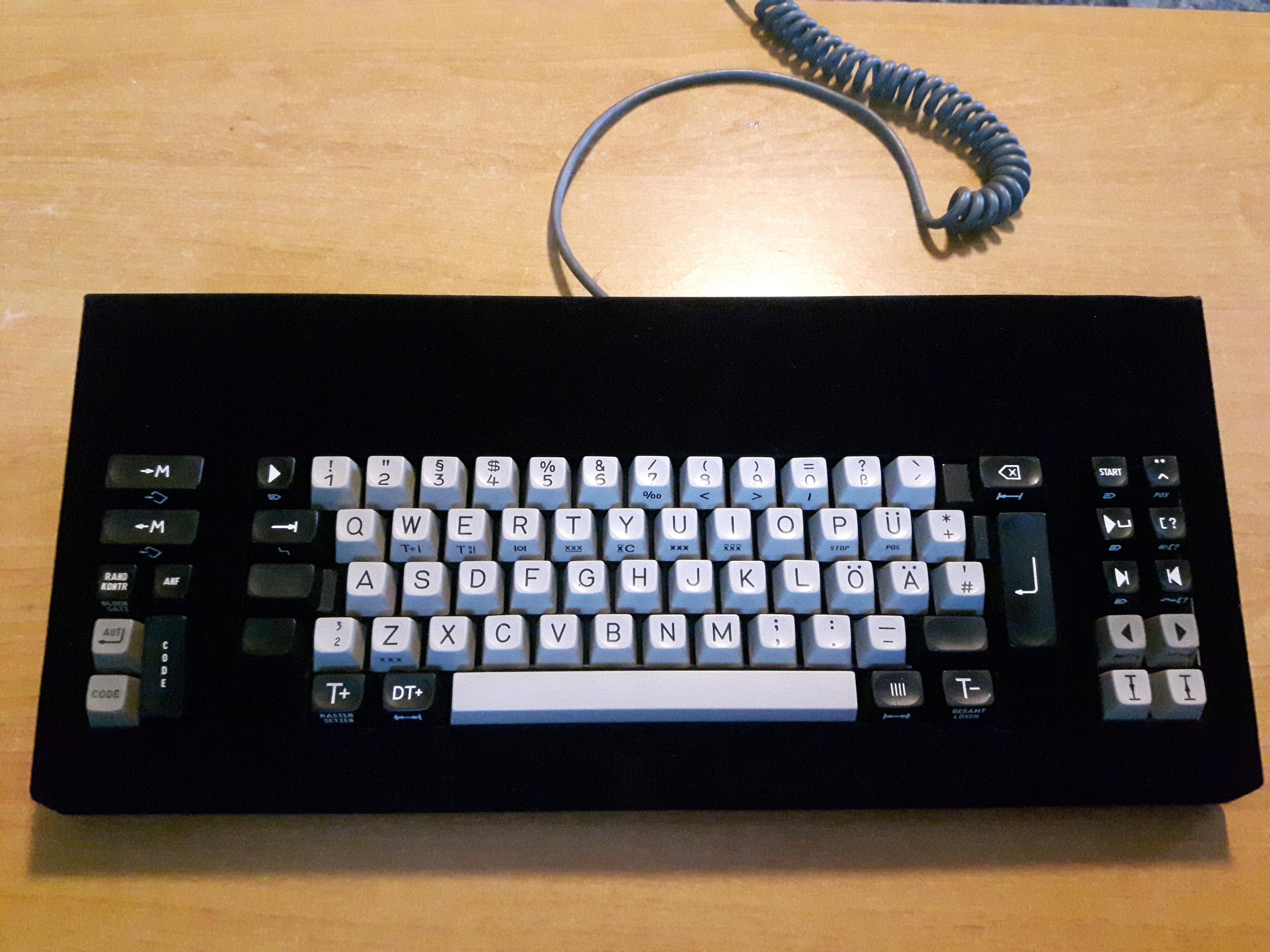
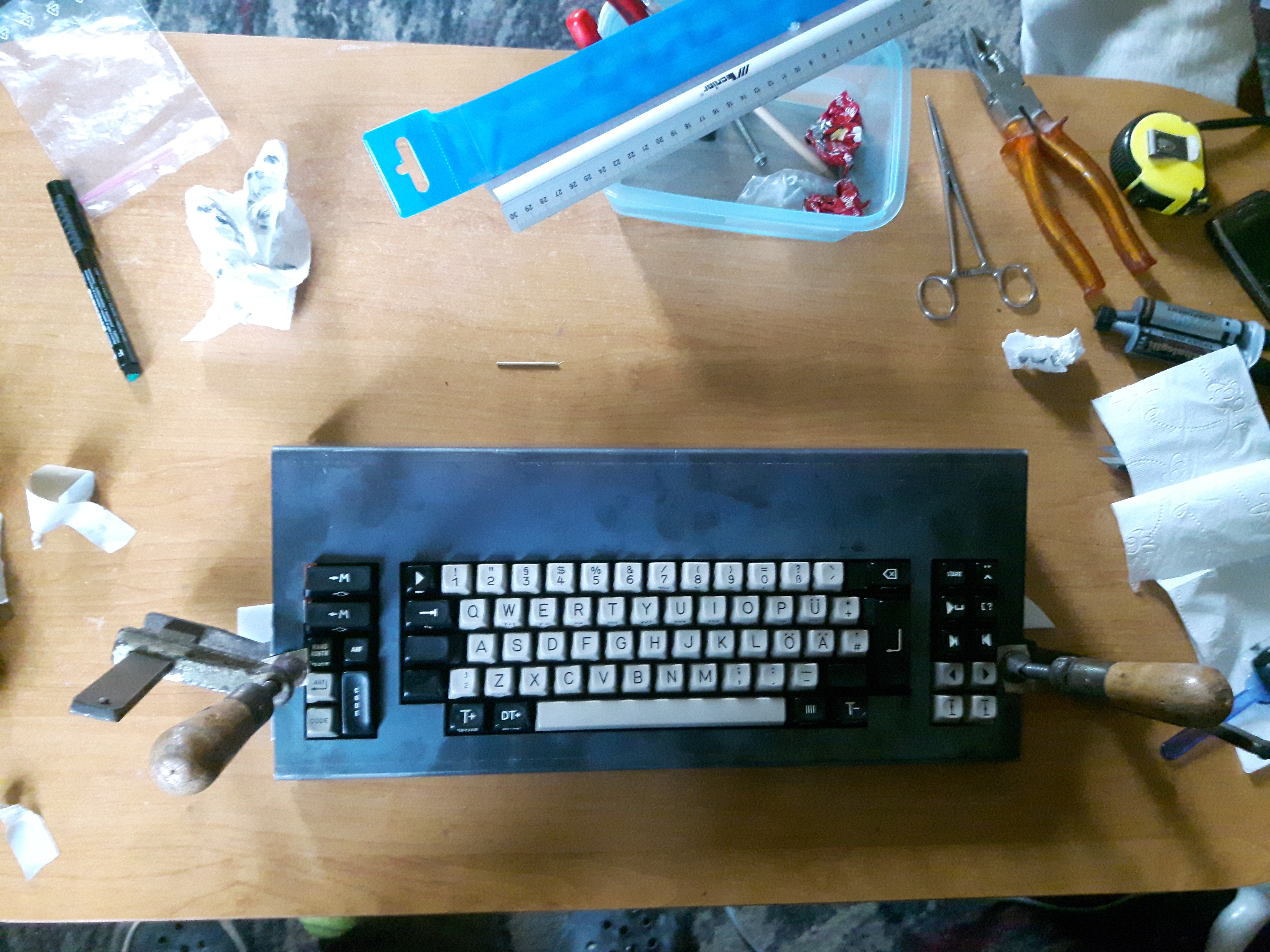
And the journey continues...
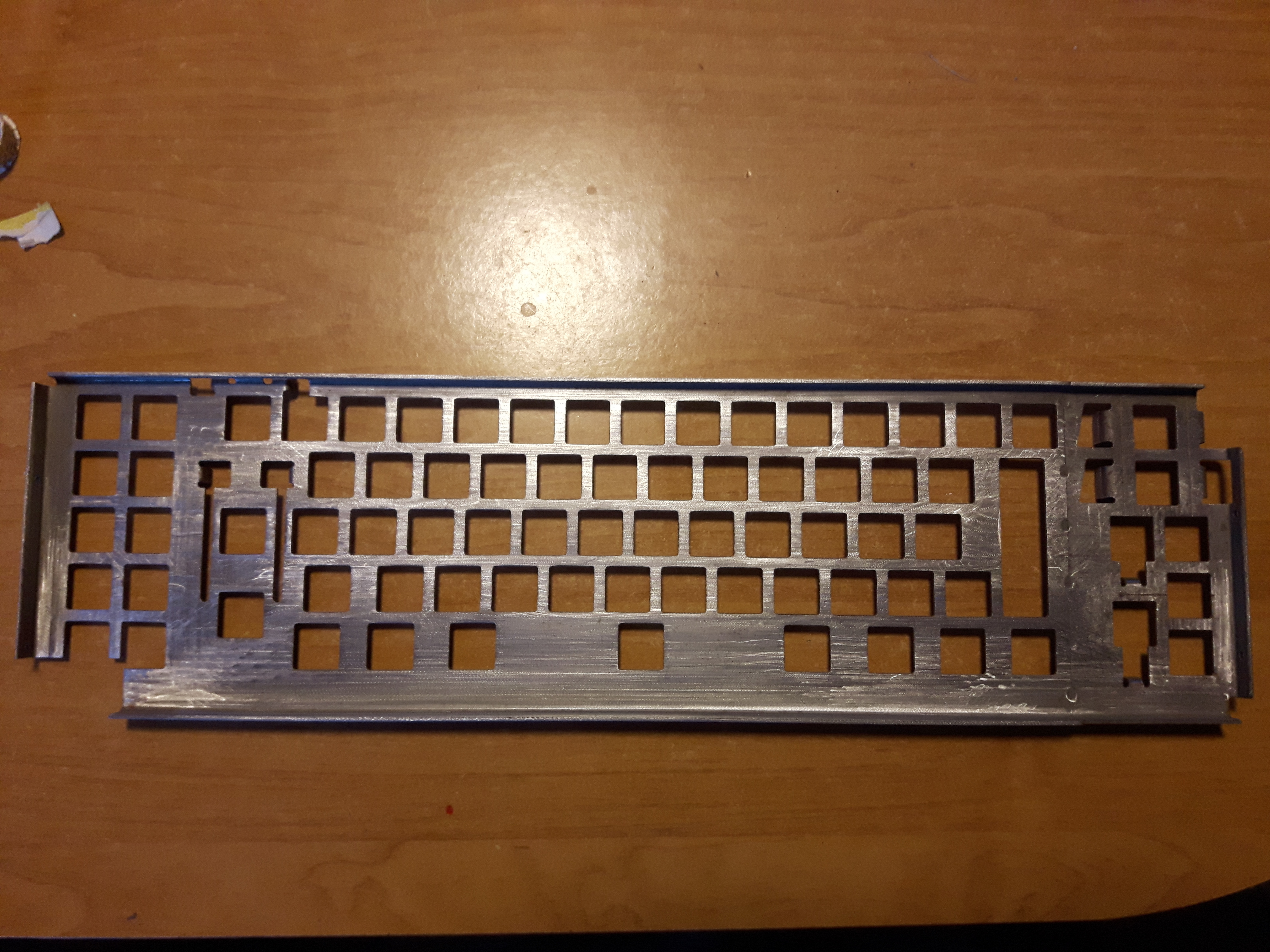
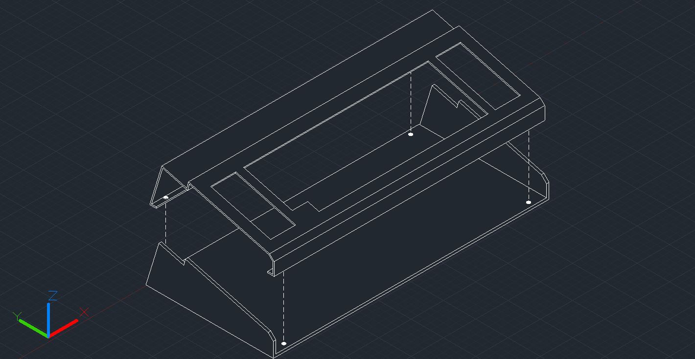
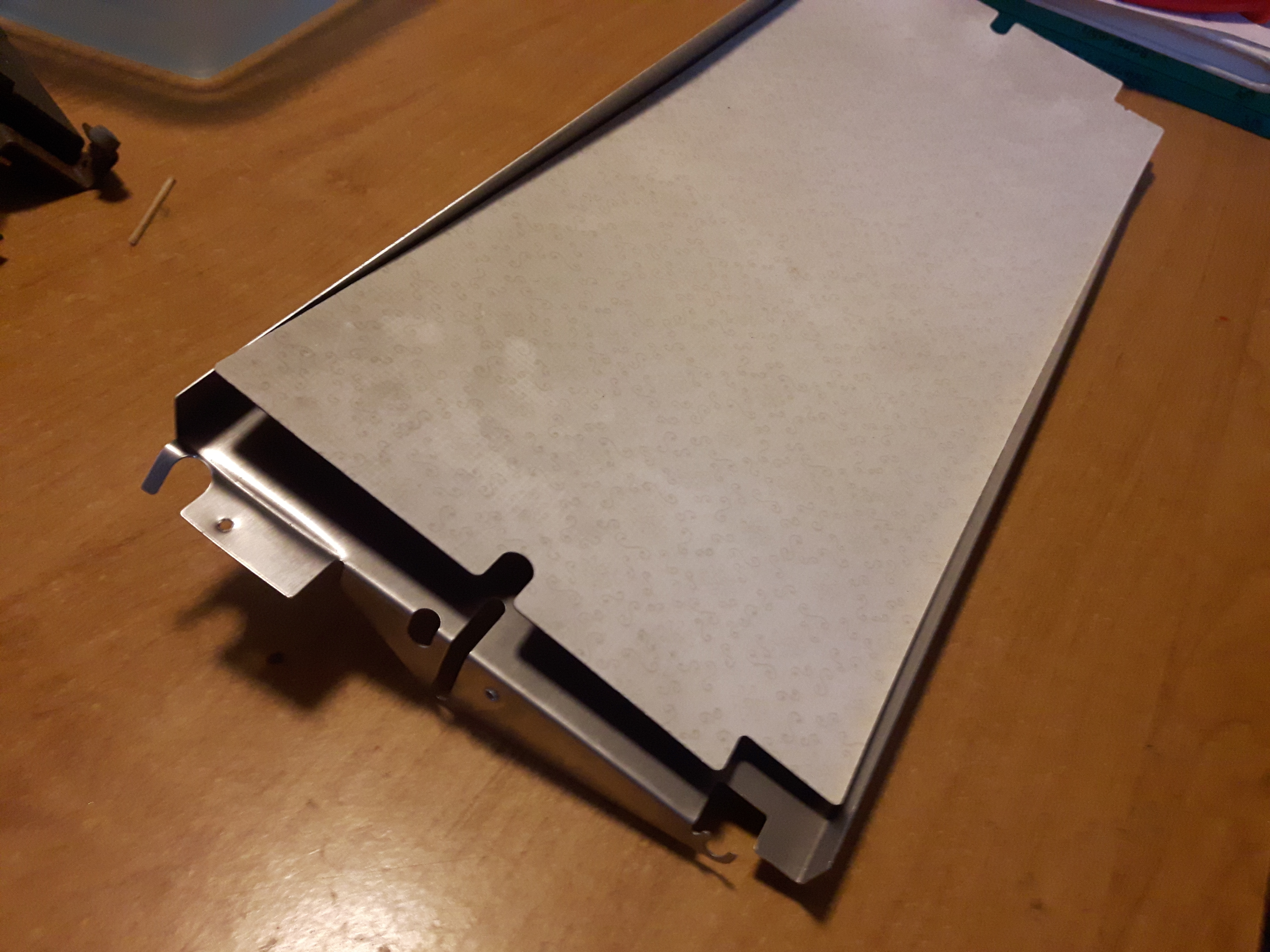
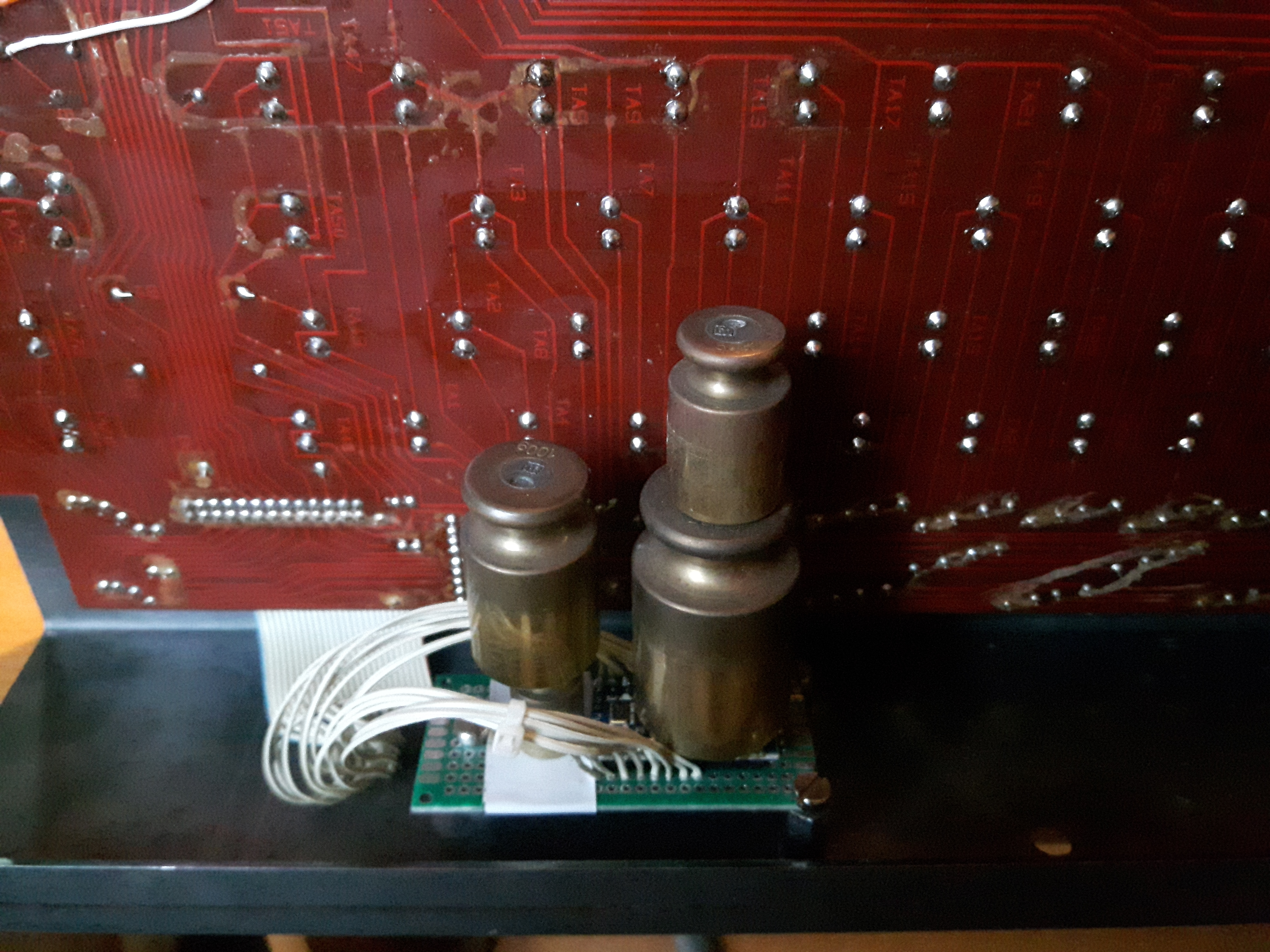
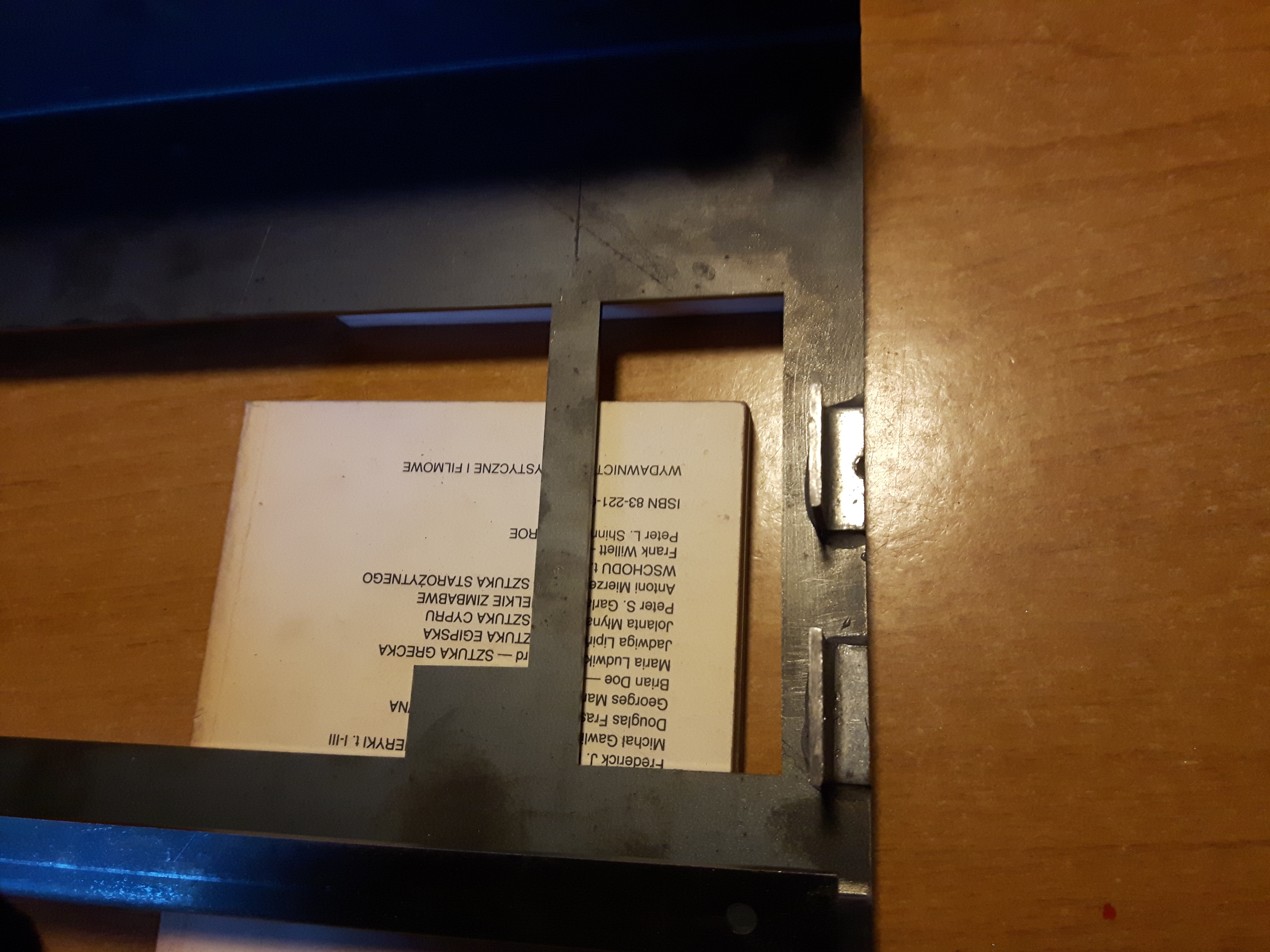
Did some measuring of the space between switchplate and the case. Cut some metal brackets and drilled the holes.
Then glued those brackets to the case.
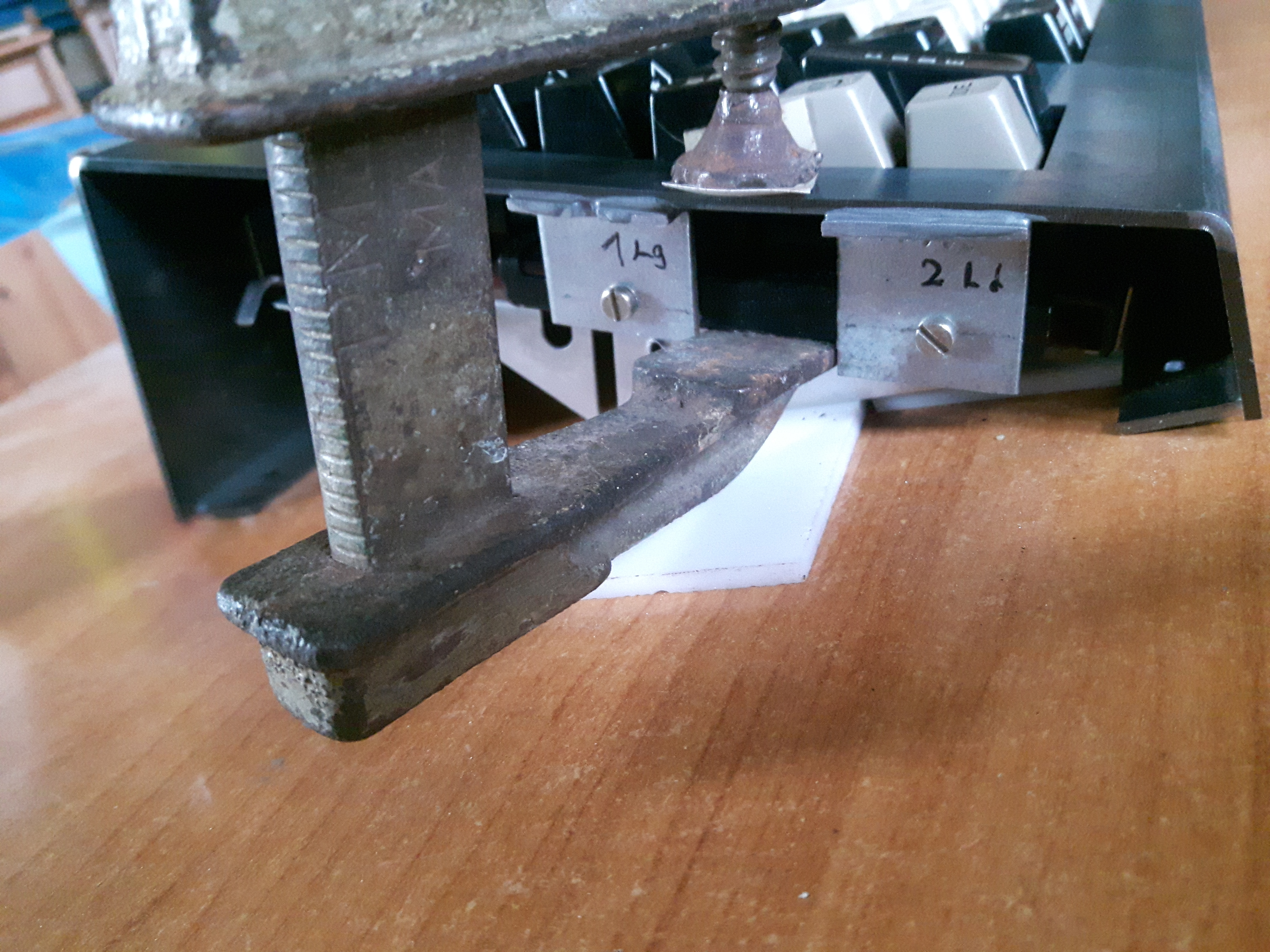
Left it curing for 24 hours.
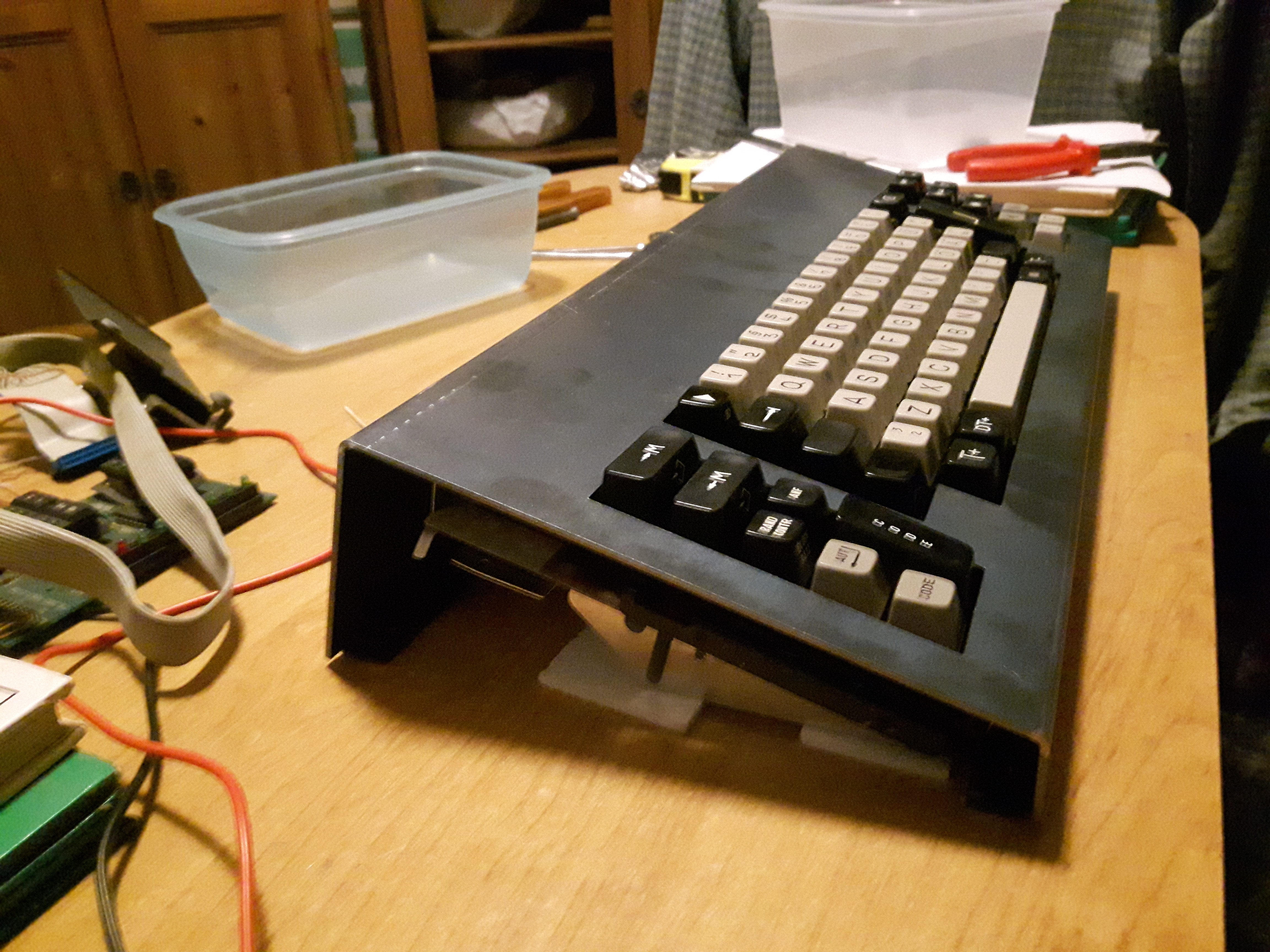
To be honest I wasn't convinced about the strength of such glue. So I did couple of drop tests from various heights.
Up to 60-70 cm I believe. And it survived just fine. Pretty happy that welding it together wasn't necessary.
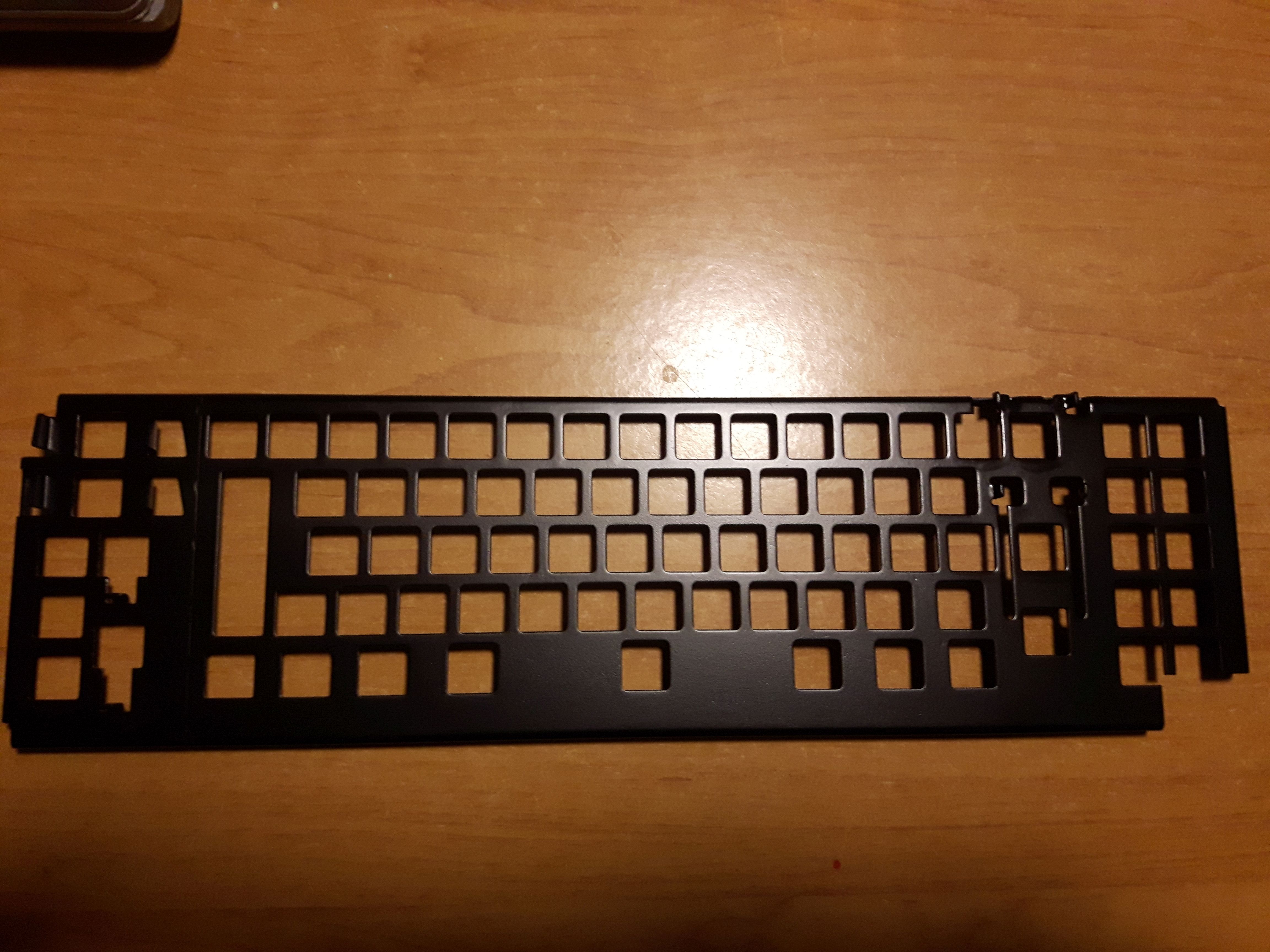
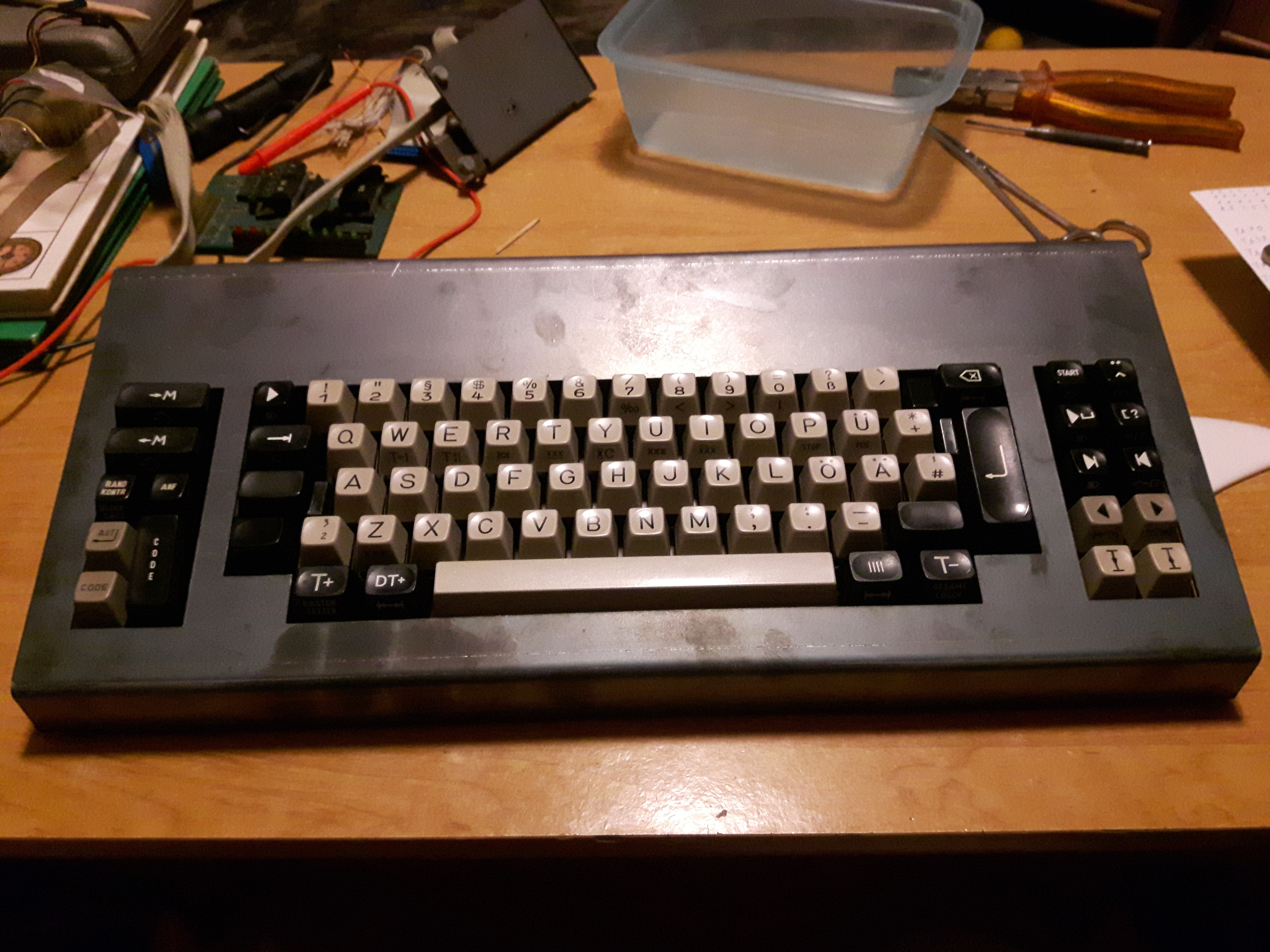
Next thing was trimming everything that sticks out.
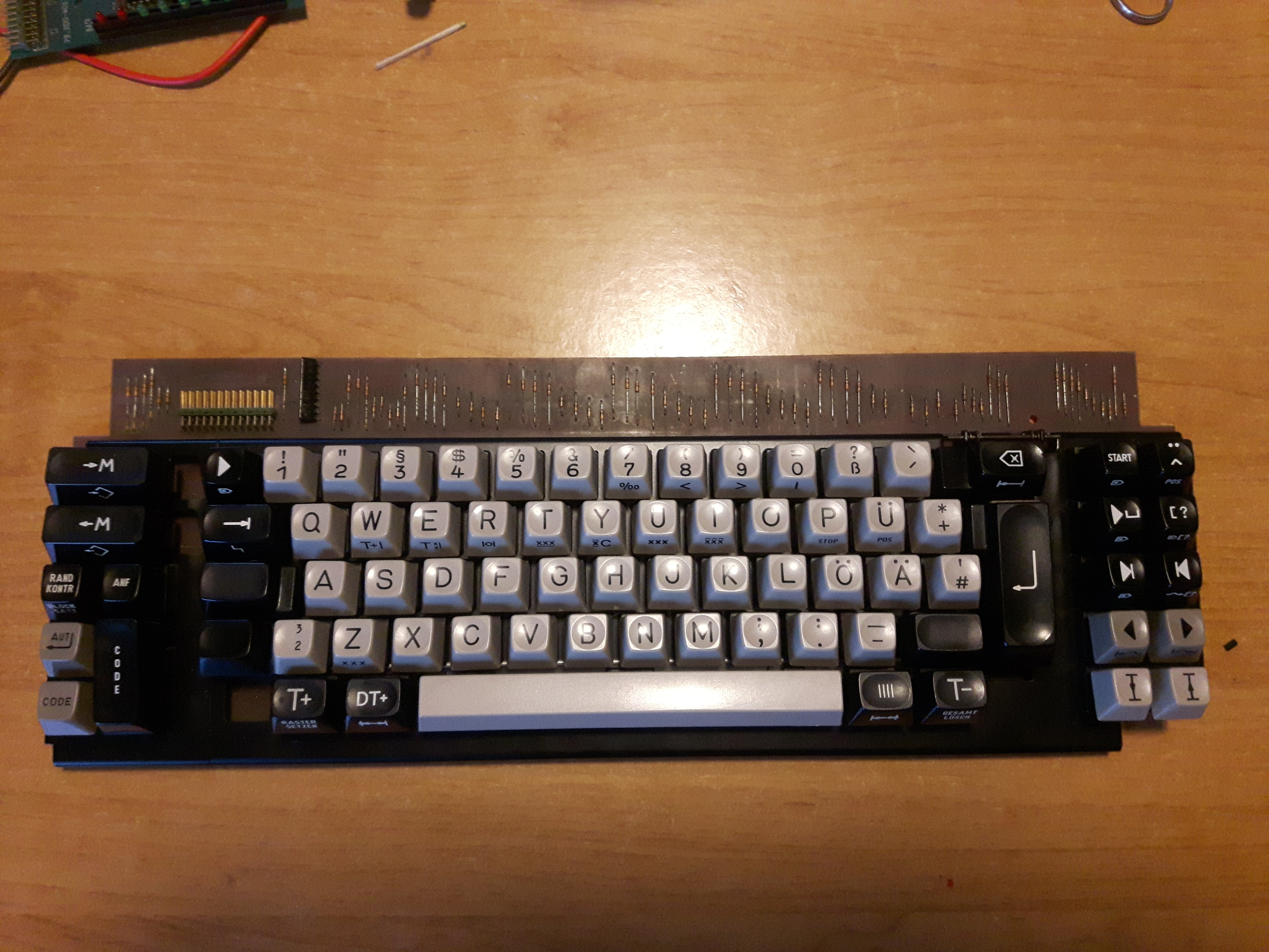
With that out of the way. It's firmware time.
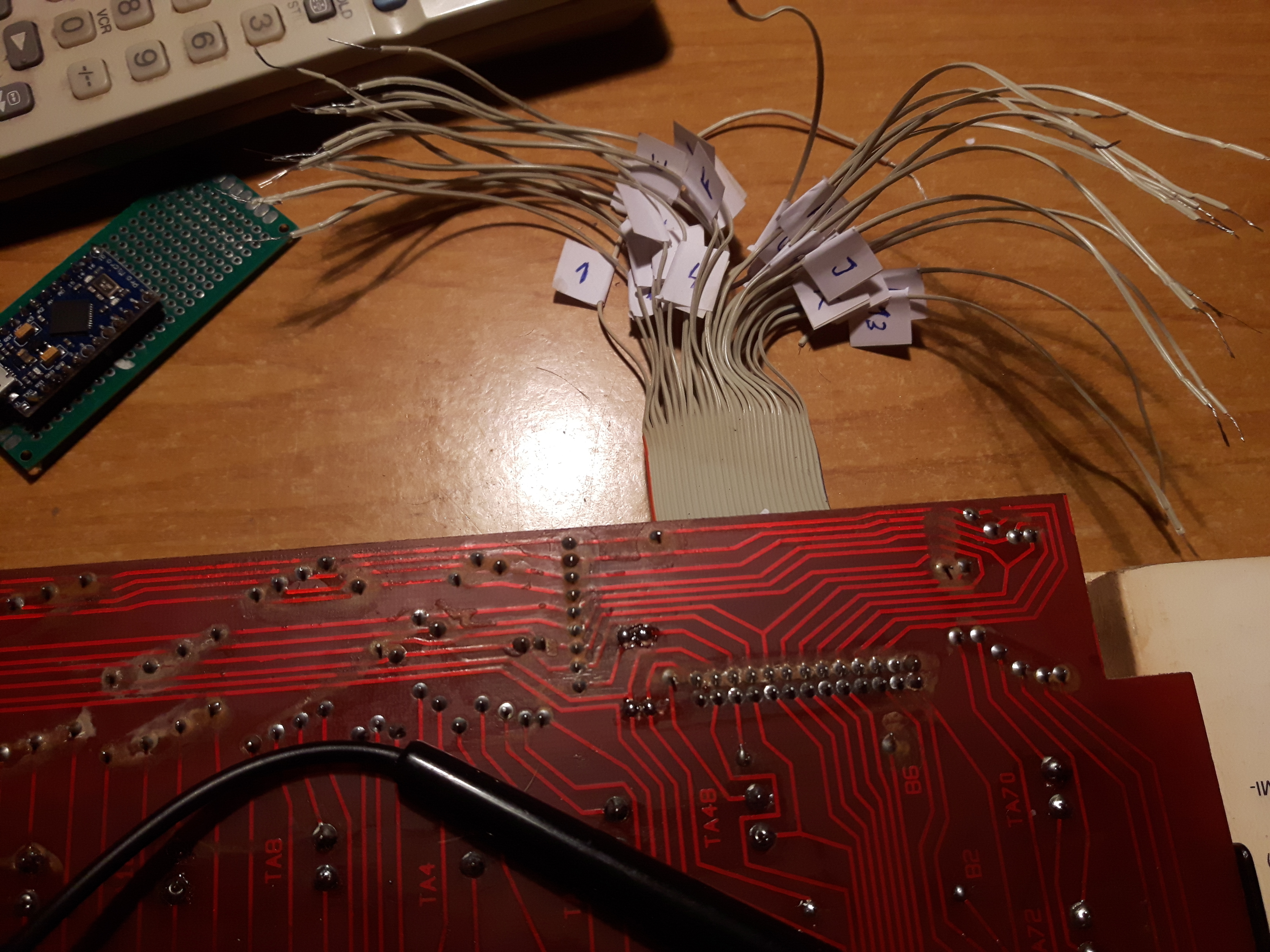
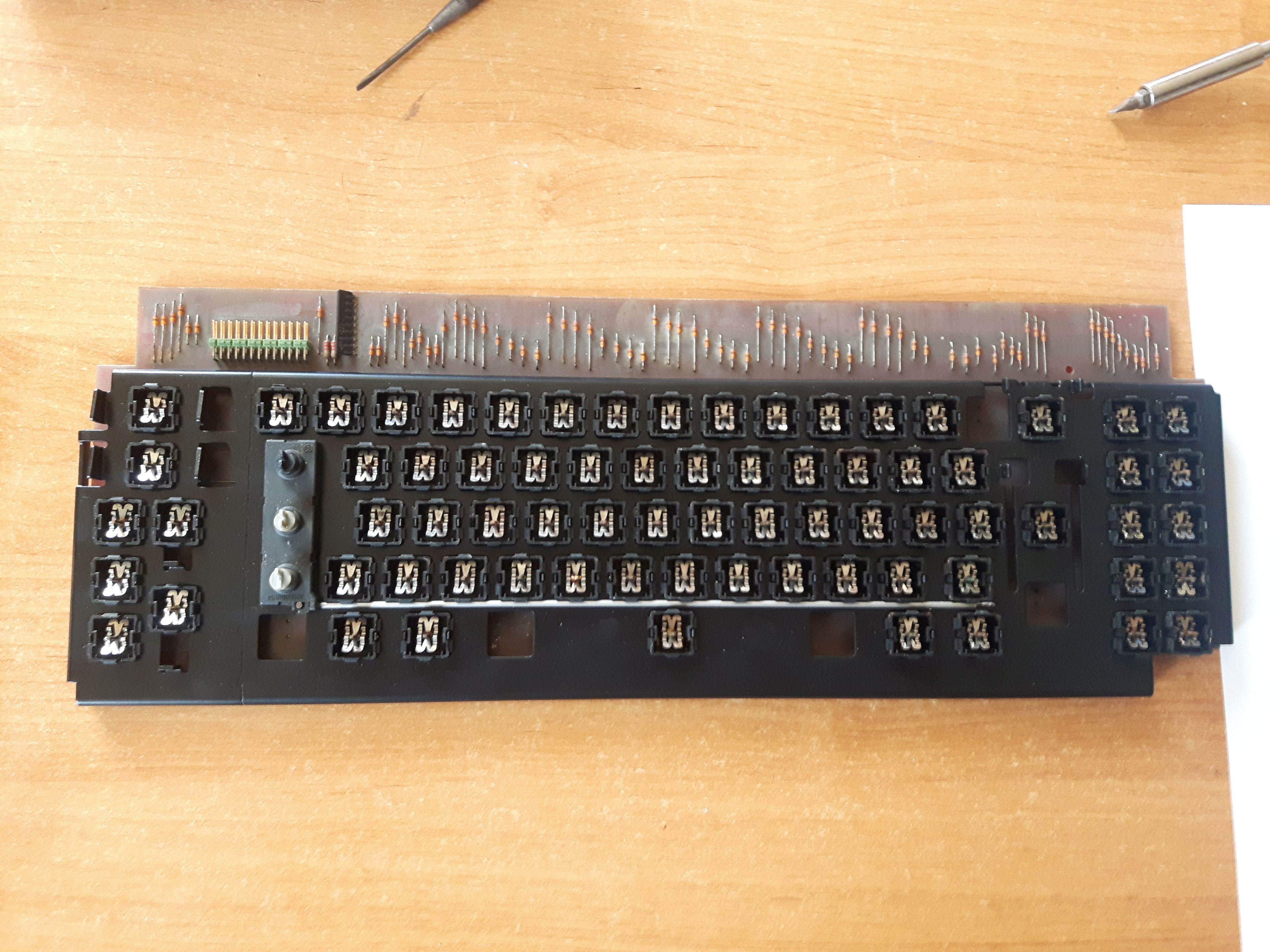
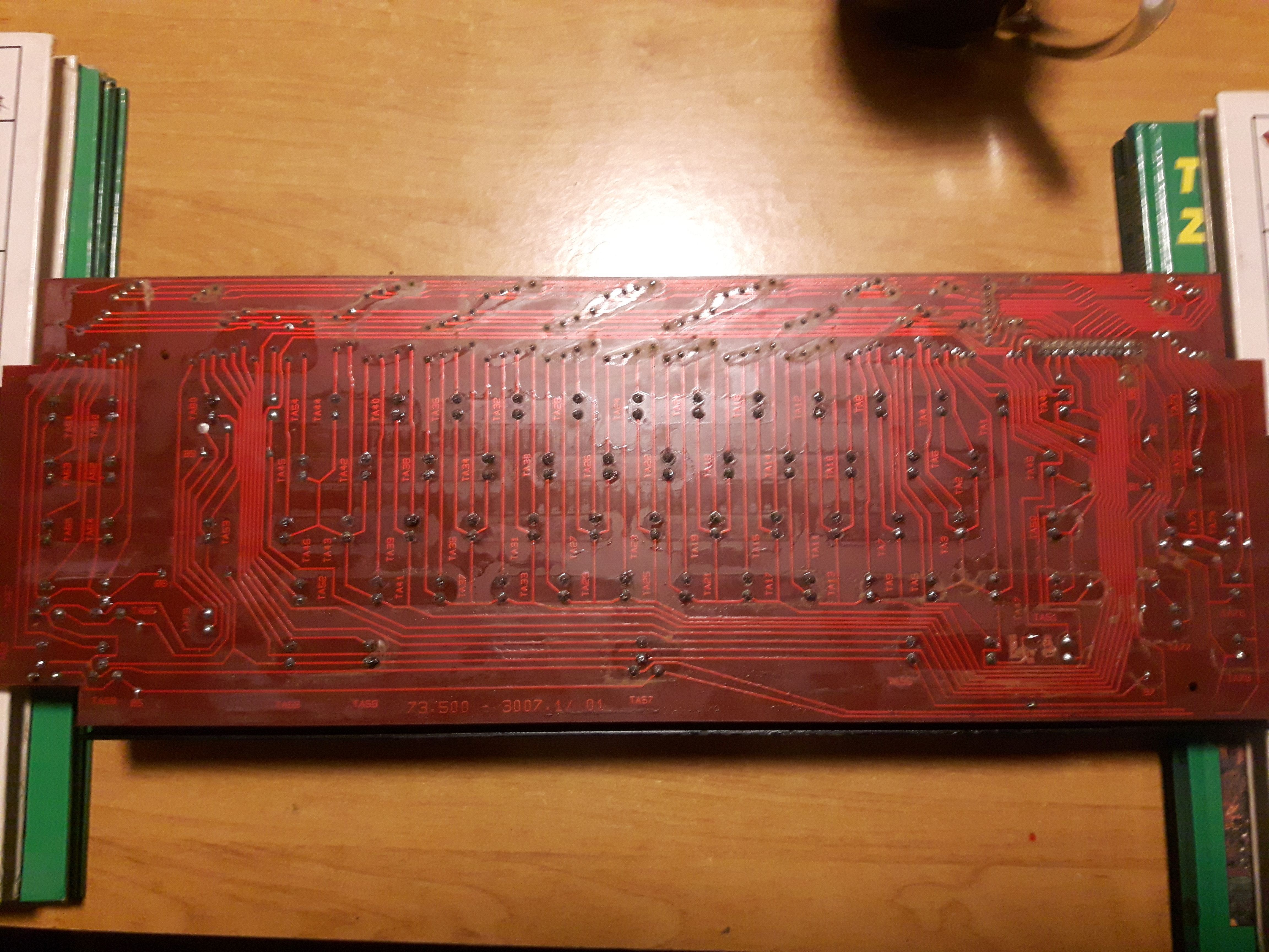
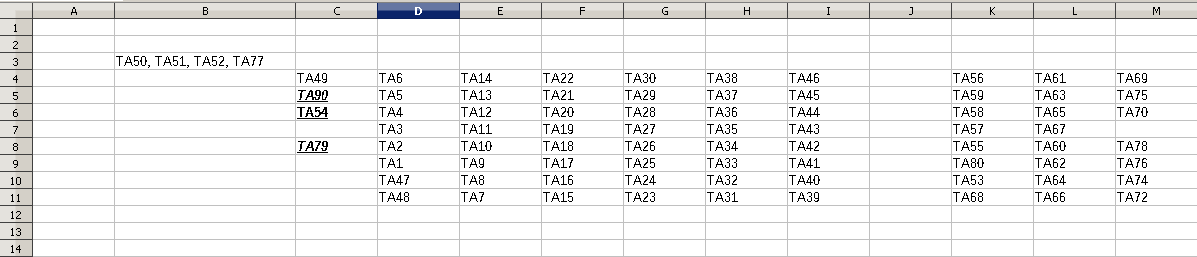
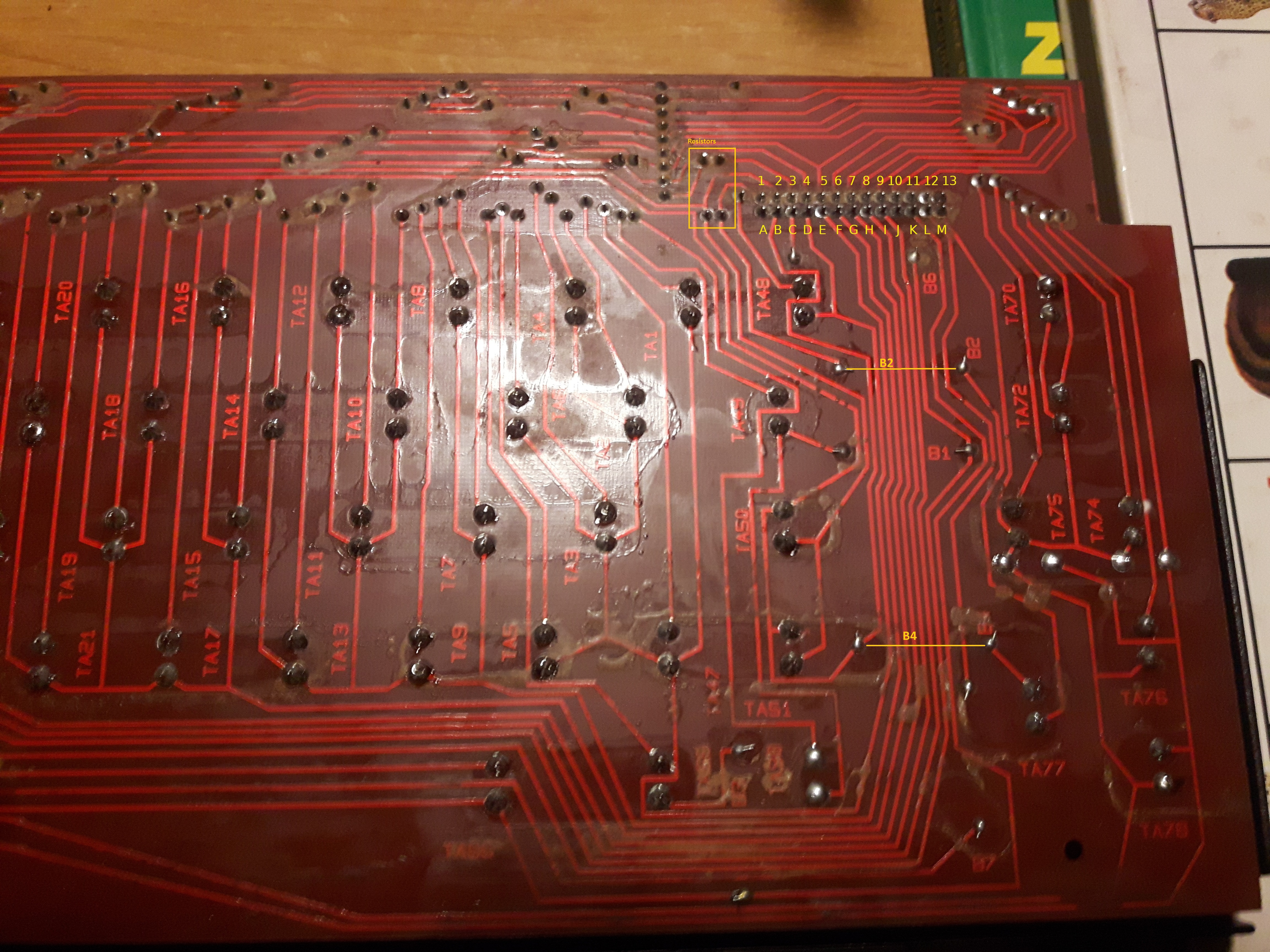
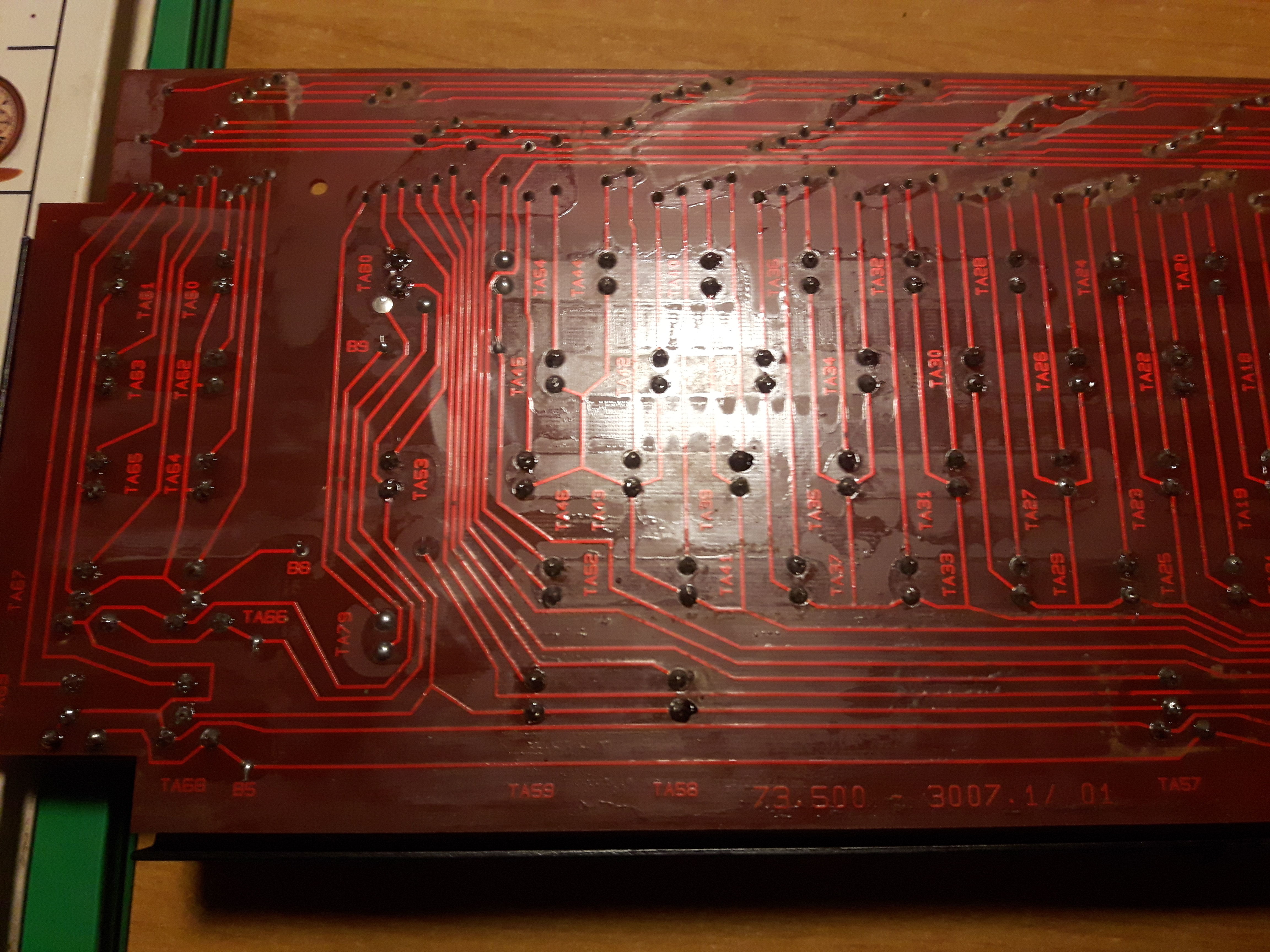
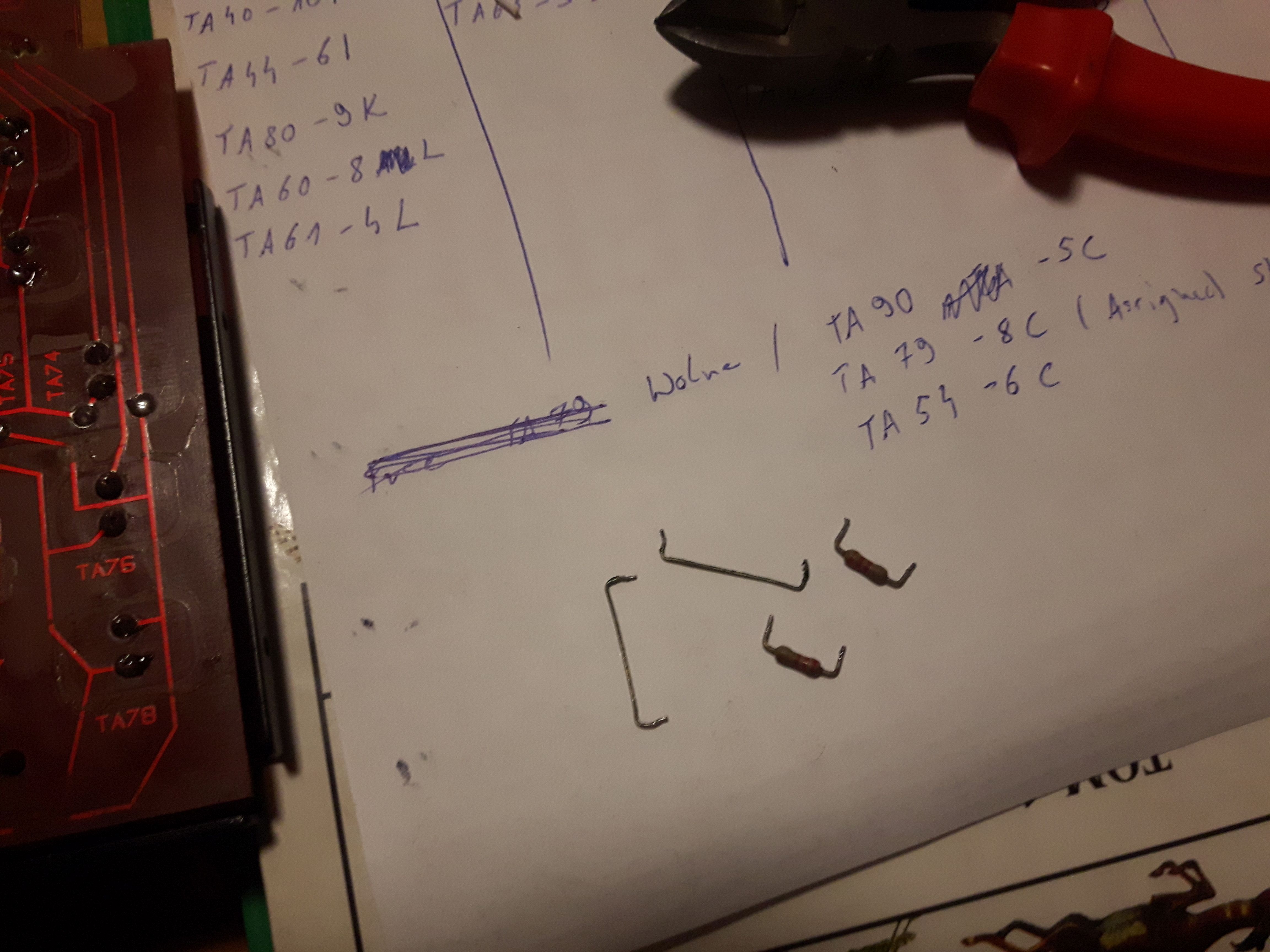
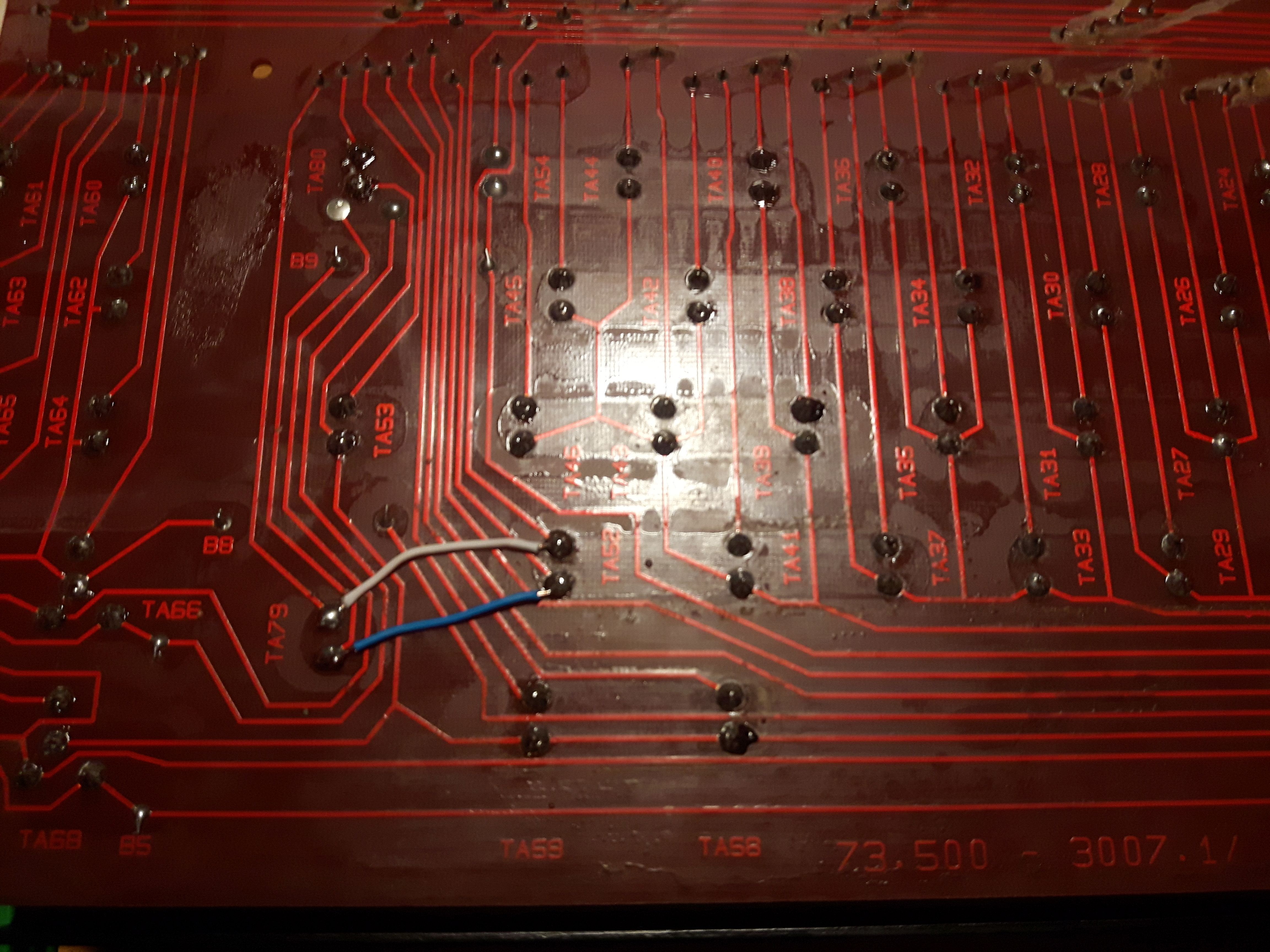
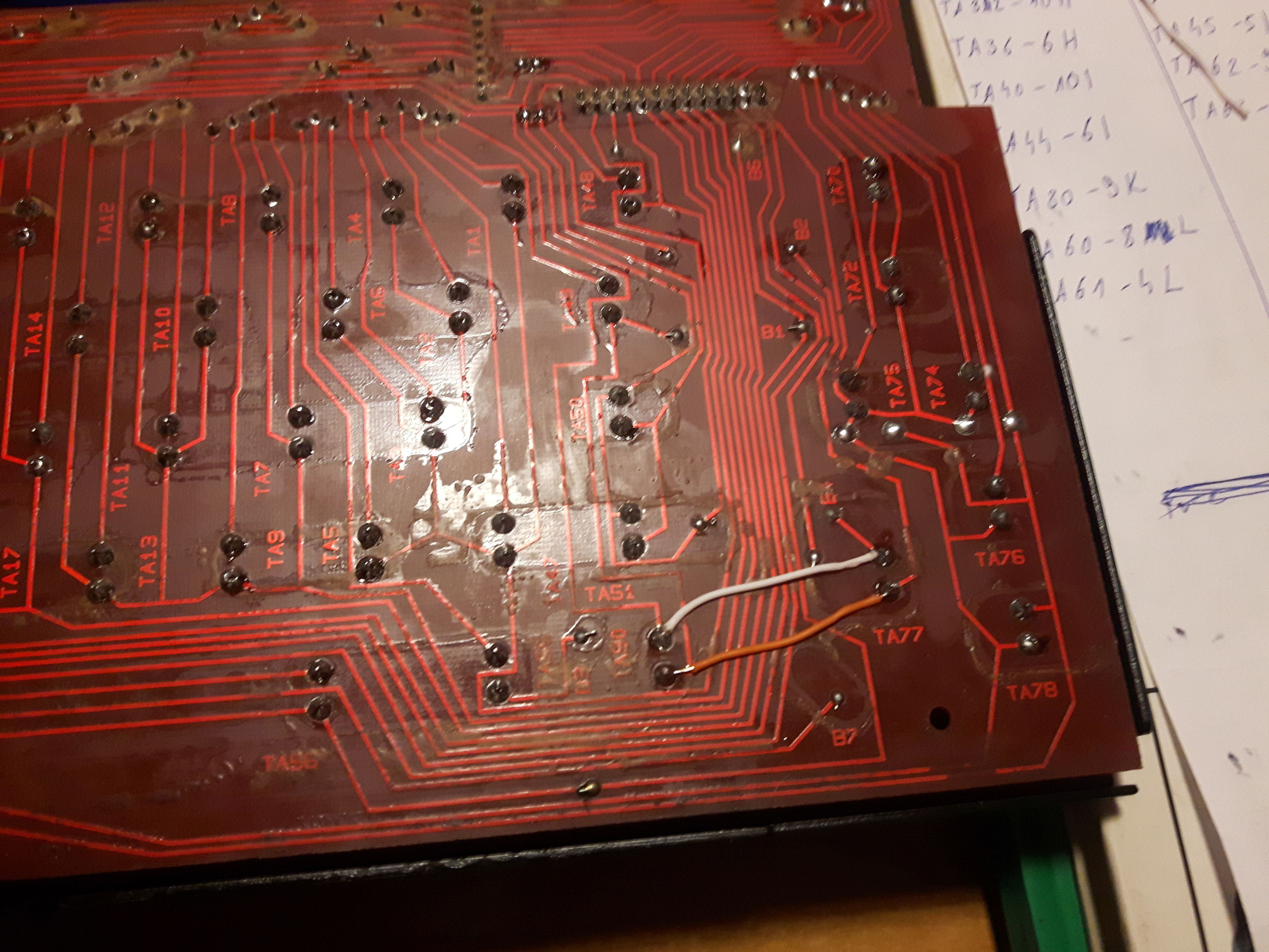
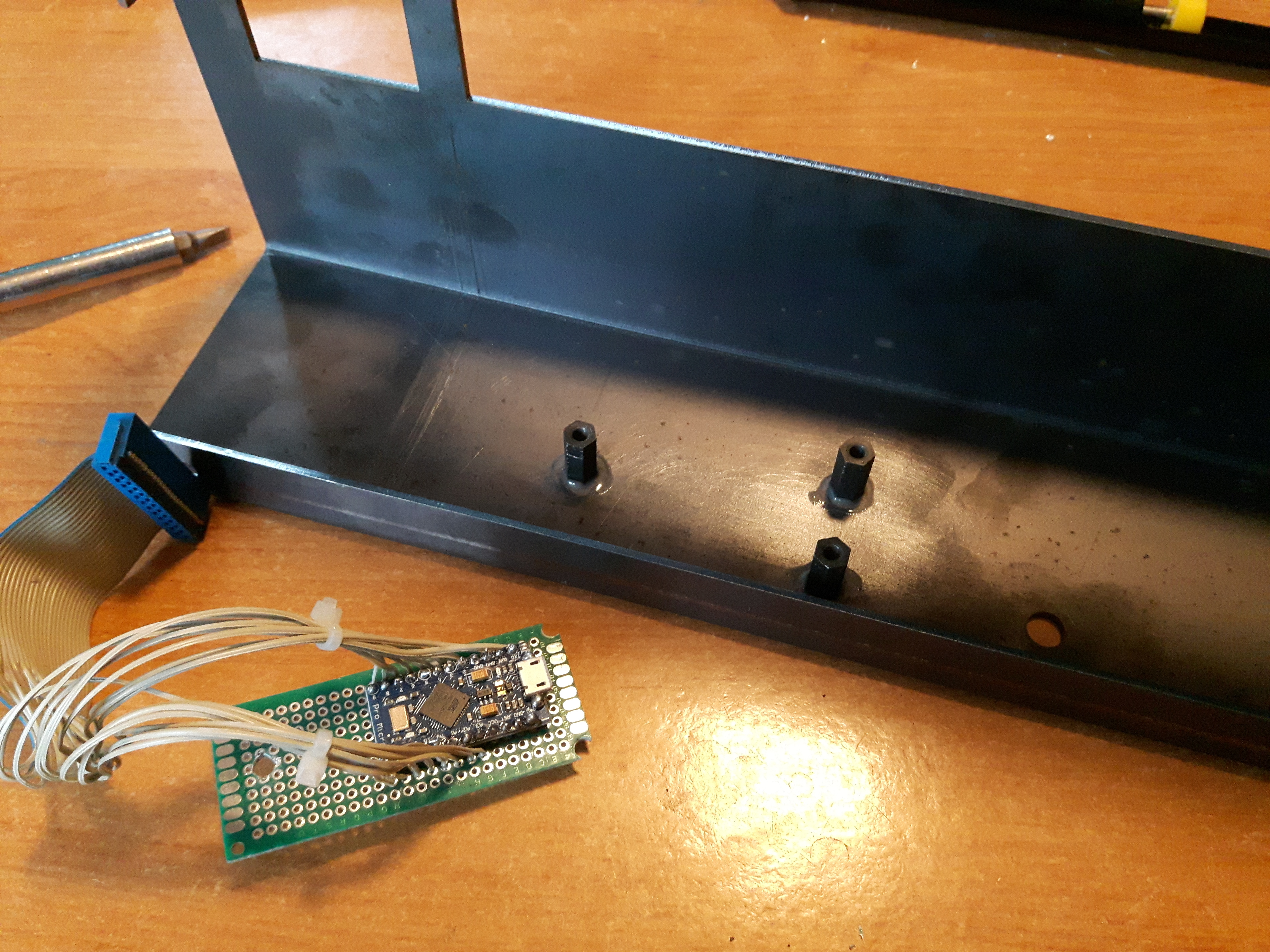
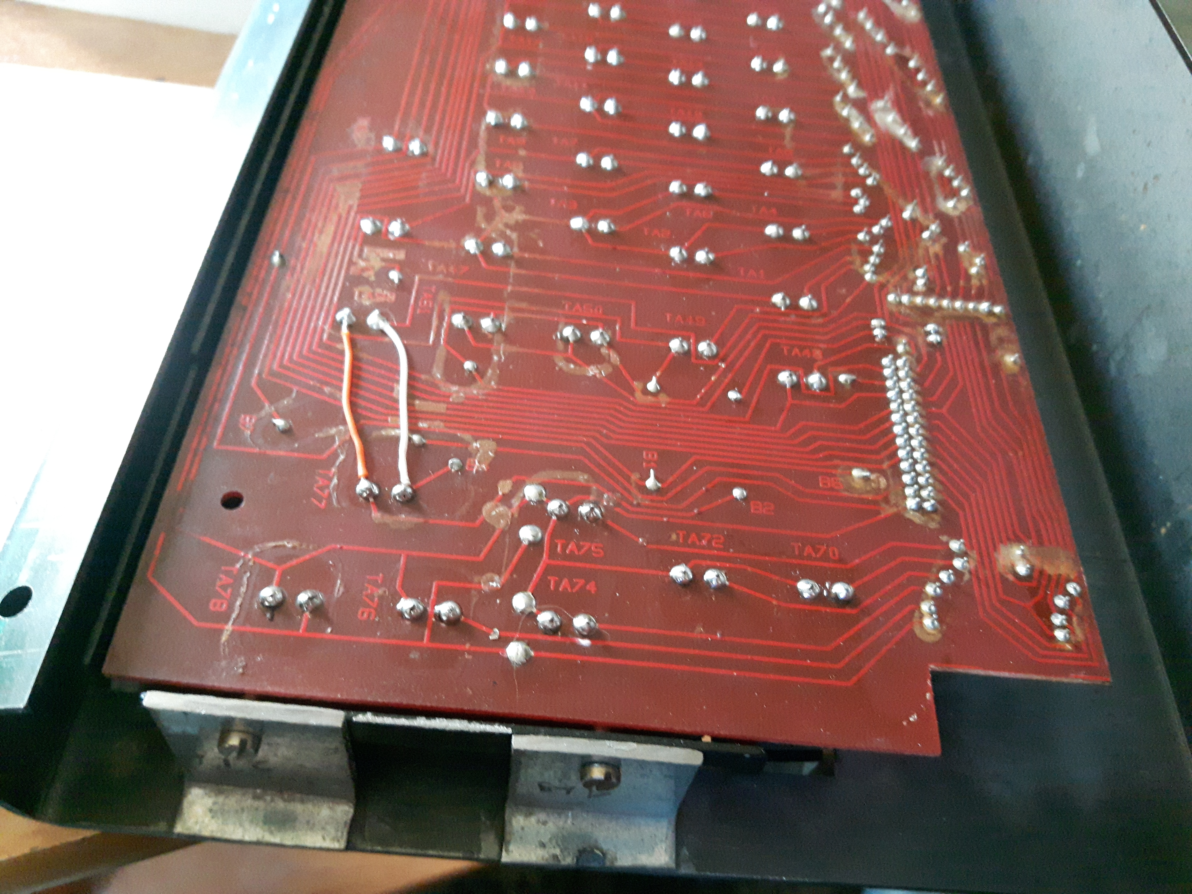
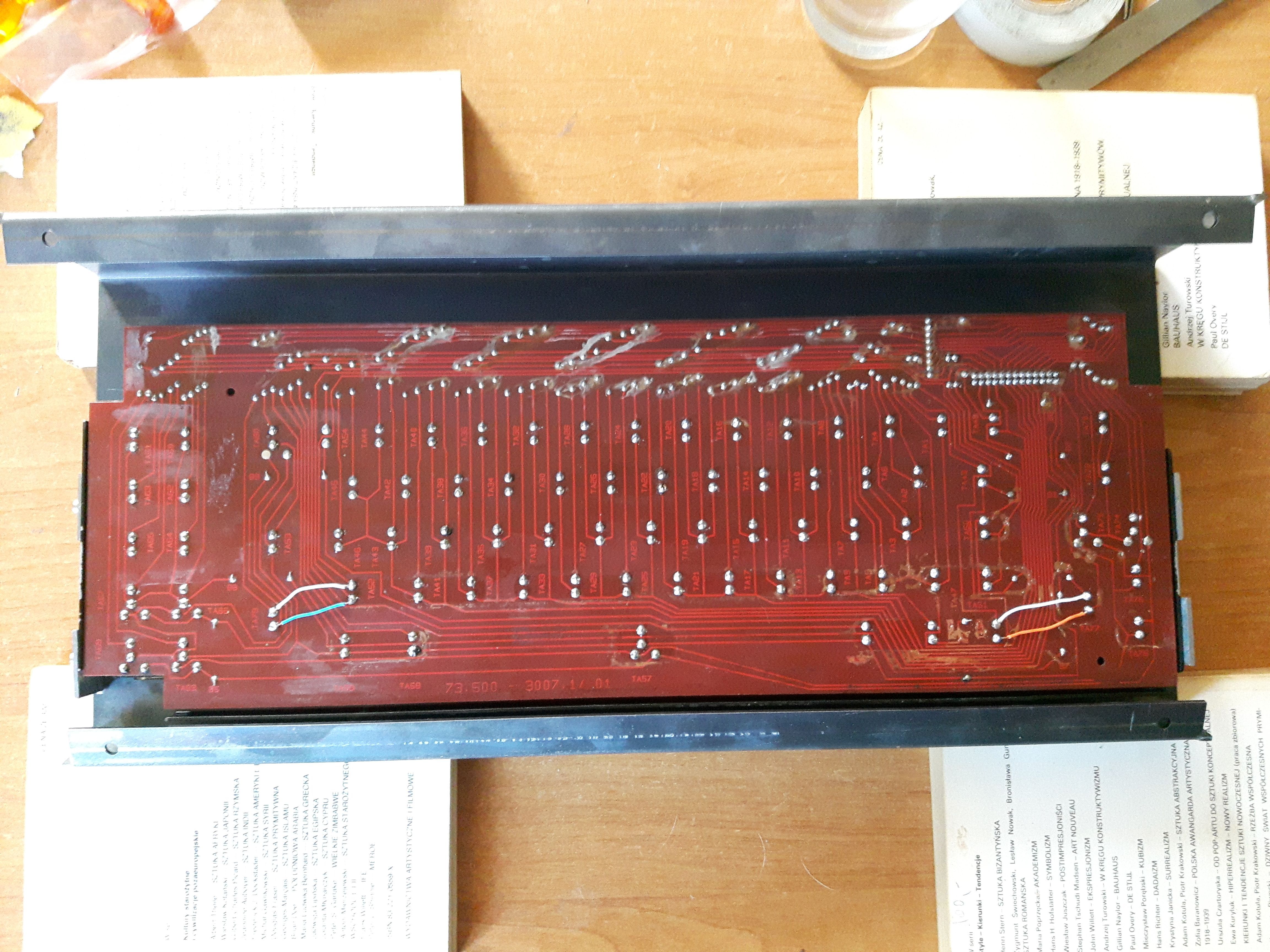
Marked every single wire to prevent confusion during soldering. And attached Pro Micro to the dummy board.
This will give me the room for reset button which this board lacks. And mounting holes for screws.
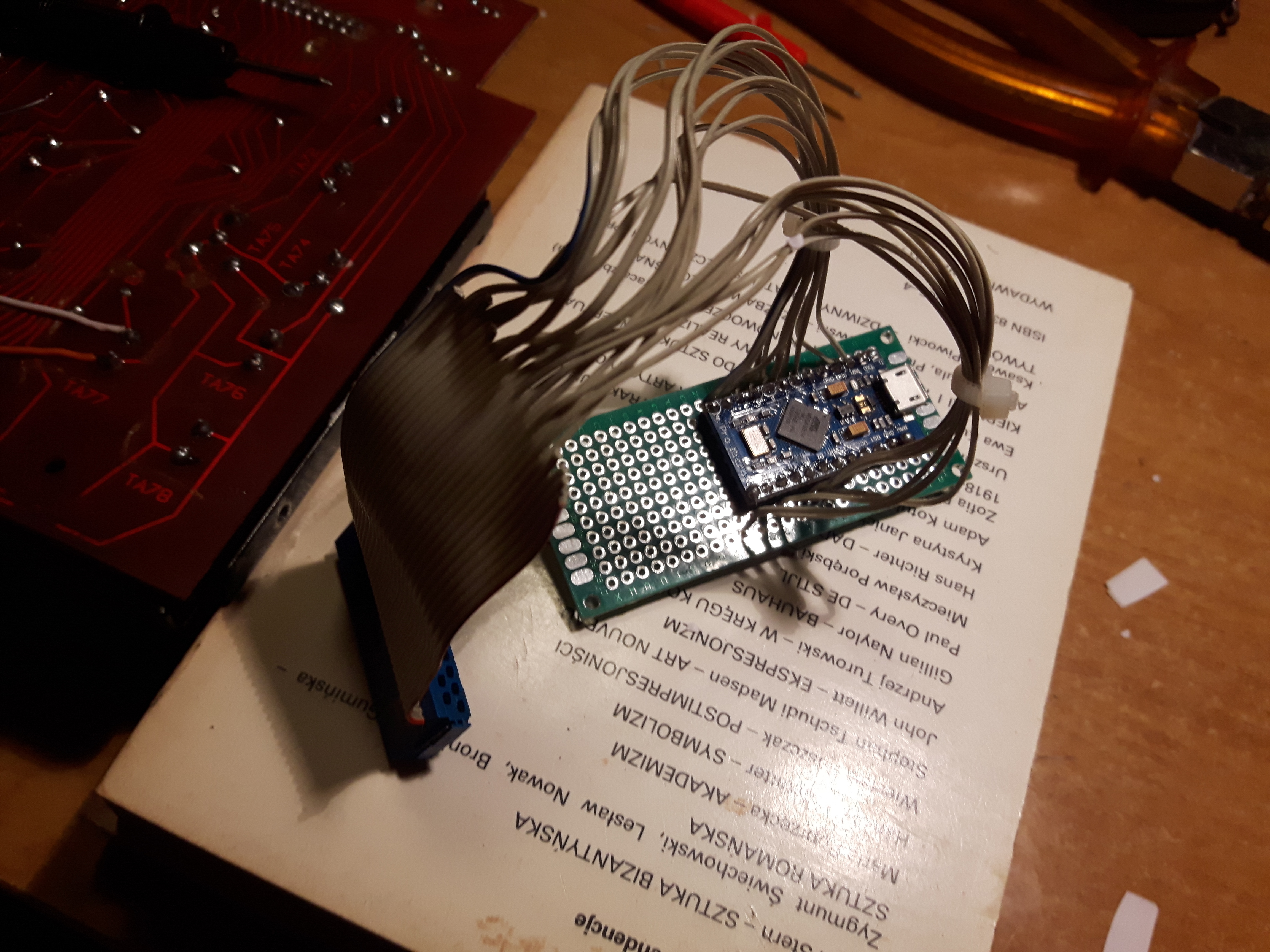
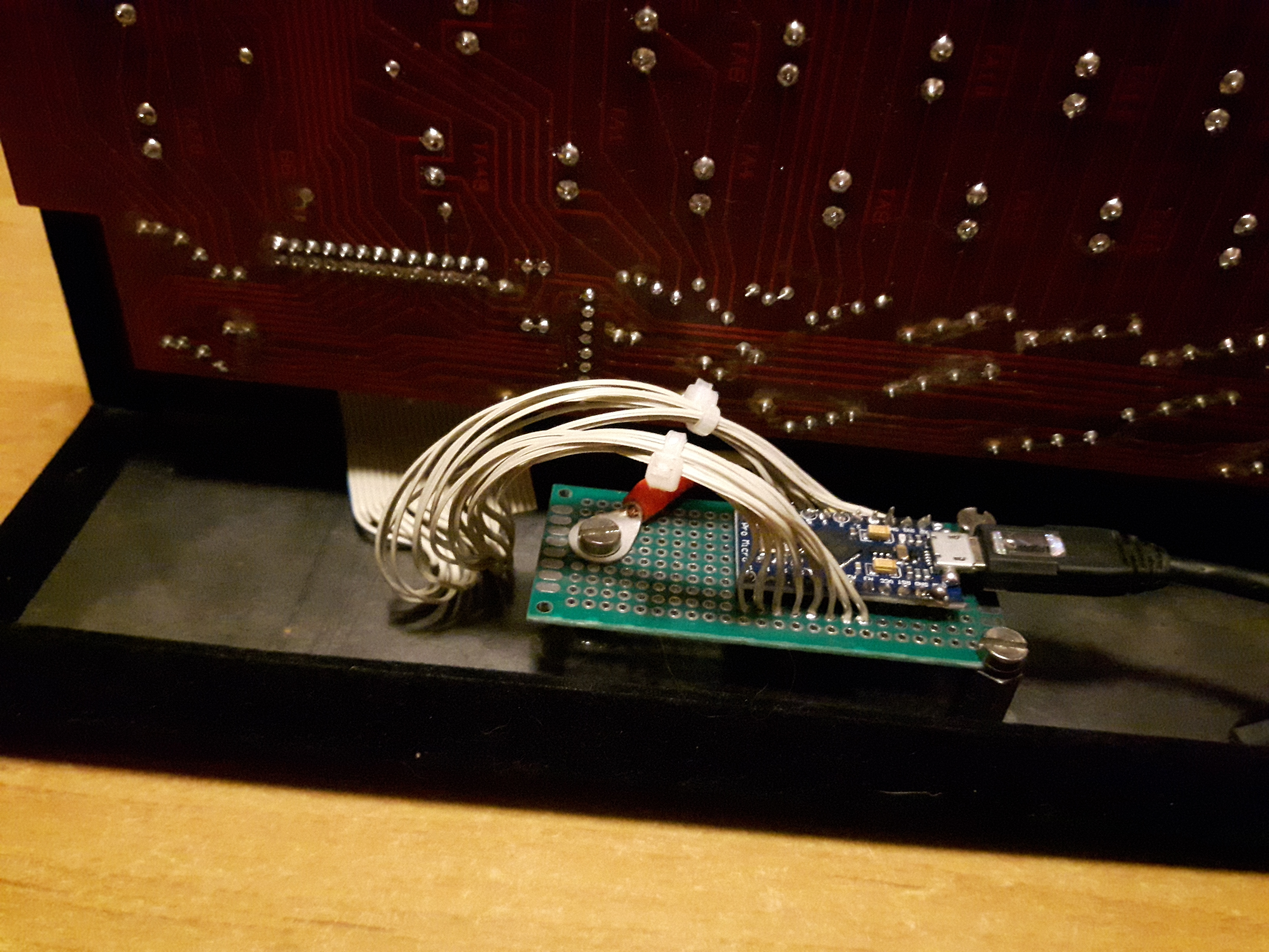
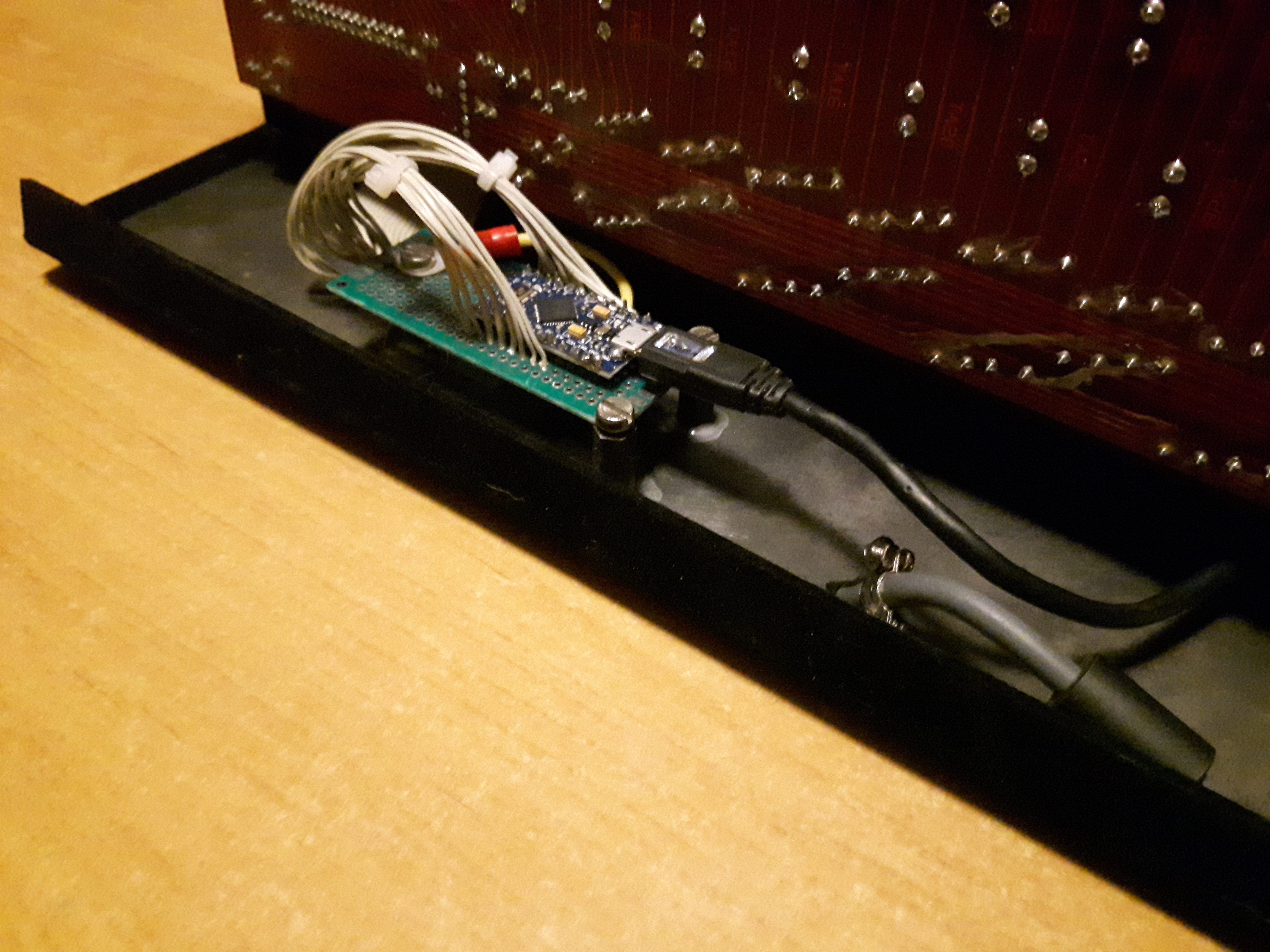
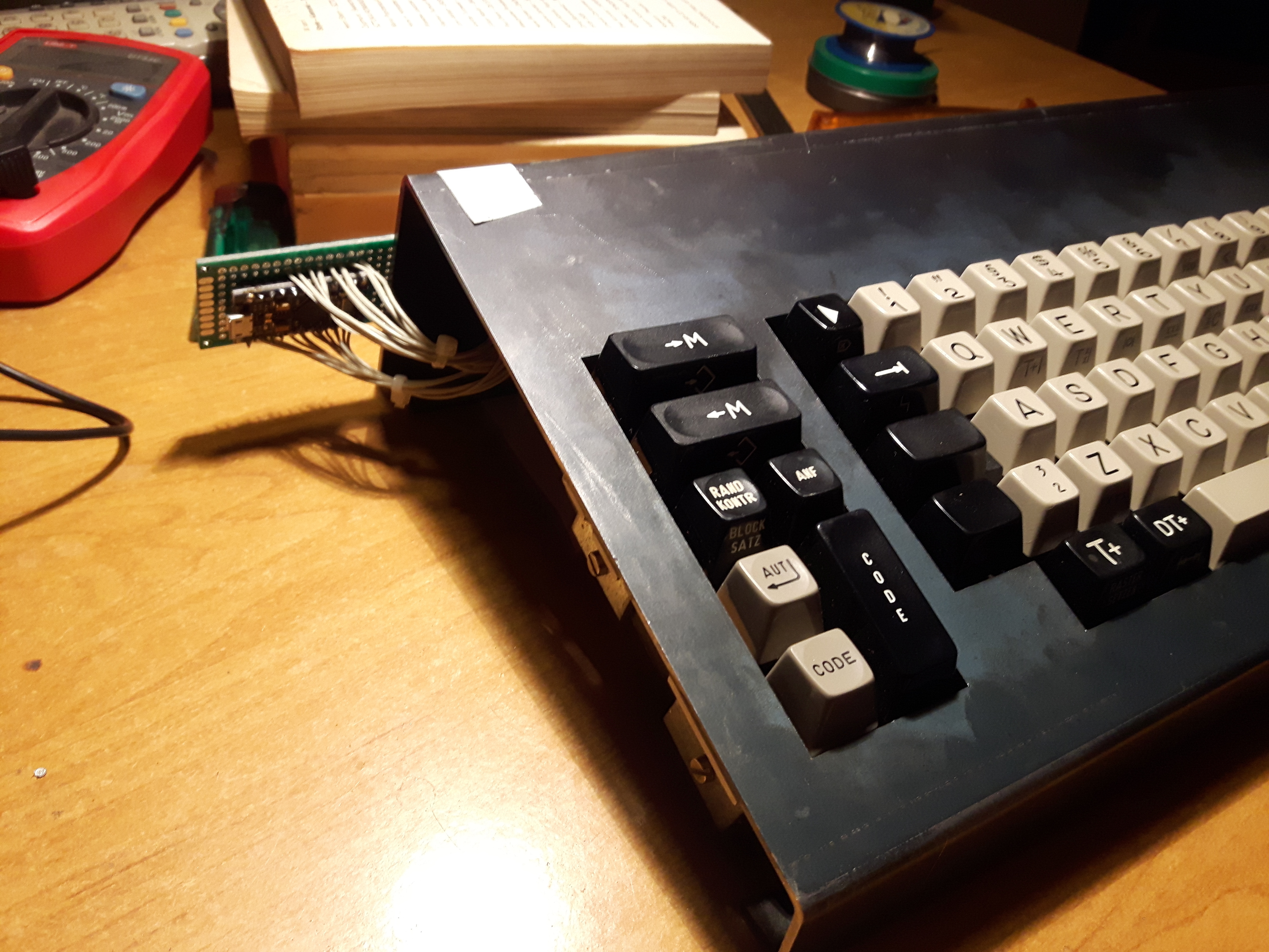
And everything connected and ready for testing.
Since my current machine is Win7 laptop (yeah I know) . I had to set up the environment from the ground up.
But all went smooth due to very good QMK documentation. Used included script to make new keyboard and edited template files accordingly.
rules.mk
Code: Select all
# MCU name
MCU = atmega32u4

# Bootloader selection
#   Teensy       halfkay
#   Pro Micro    caterina
#   Atmel DFU    atmel-dfu
#   LUFA DFU     lufa-dfu
#   QMK DFU      qmk-dfu
#   ATmega32A    bootloadHID
#   ATmega328P   USBasp
BOOTLOADER = caterina

# If you don't know the bootloader type, then you can specify the
# Boot Section Size in *bytes* by uncommenting out the OPT_DEFS line
# Otherwise, delete this section
#   Teensy halfKay      512
#   Teensy++ halfKay    1024
#   Atmel DFU loader    4096
#   LUFA bootloader     4096
#   USBaspLoader        2048
# OPT_DEFS += -DBOOTLOADER_SIZE=4096

# Build Options
#   change yes to no to disable
#
BOOTMAGIC_ENABLE = no       # Virtual DIP switch configuration
MOUSEKEY_ENABLE = no       # Mouse keys
EXTRAKEY_ENABLE = no       # Audio control and System control
CONSOLE_ENABLE = no        # Console for debug
COMMAND_ENABLE = no        # Commands for debug and configuration
# Do not enable SLEEP_LED_ENABLE. it uses the same timer as BACKLIGHT_ENABLE
SLEEP_LED_ENABLE = no       # Breathing sleep LED during USB suspend
# if this doesn't work, see here: https://github.com/tmk/tmk_keyboard/wiki/FAQ#nkro-doesnt-work
NKRO_ENABLE = yes            # USB Nkey Rollover
BACKLIGHT_ENABLE = no       # Enable keyboard backlight functionality
RGBLIGHT_ENABLE = no        # Enable keyboard RGB underglow
MIDI_ENABLE = no            # MIDI support
BLUETOOTH_ENABLE = no       # Enable Bluetooth with the Adafruit EZ-Key HID
AUDIO_ENABLE = no           # Audio output on port C6
FAUXCLICKY_ENABLE = no      # Use buzzer to emulate clicky switches
HD44780_ENABLE = no         # Enable support for HD44780 based LCDs
Code: Select all
/*
Copyright 2019 azg

This program is free software: you can redistribute it and/or modify
it under the terms of the GNU General Public License as published by
the Free Software Foundation, either version 2 of the License, or
(at your option) any later version.

This program is distributed in the hope that it will be useful,
but WITHOUT ANY WARRANTY; without even the implied warranty of
MERCHANTABILITY or FITNESS FOR A PARTICULAR PURPOSE.  See the
GNU General Public License for more details.

You should have received a copy of the GNU General Public License
along with this program.  If not, see <http://www.gnu.org/licenses/>.
*/

#pragma once

#include "config_common.h"

/* USB Device descriptor parameter */
#define VENDOR_ID 0xFDDD
#define PRODUCT_ID 0x5486
#define DEVICE_VER 0x0011
#define MANUFACTURER azg
#define PRODUCT Olympia ES110
#define DESCRIPTION A custom keyboard

/* key matrix size */
#define MATRIX_ROWS 8
#define MATRIX_COLS 10

/*
 * Keyboard Matrix Assignments
 *
 * Change this to how you wired your keyboard
 * COLS: AVR pins used for columns, left to right
 * ROWS: AVR pins used for rows, top to bottom
 * DIODE_DIRECTION: COL2ROW = COL = Anode (+), ROW = Cathode (-, marked on diode)
 *                  ROW2COL = ROW = Anode (+), COL = Cathode (-, marked on diode)
 *
 */
#define MATRIX_ROW_PINS { F4, F5, F6, F7, B1, B3, B2, B6 }
#define MATRIX_COL_PINS { D3, D2, D1, D0, D4, C6, D7, E6, B4, B5 }
#define UNUSED_PINS

/* COL2ROW, ROW2COL*/
#define DIODE_DIRECTION ROW2COL

/*
 * Split Keyboard specific options, make sure you have 'SPLIT_KEYBOARD = yes' in your rules.mk, and define SOFT_SERIAL_PIN.
 */
//#define SOFT_SERIAL_PIN E6  // or D1, D2, D3, E6

// #define BACKLIGHT_PIN B7
// #define BACKLIGHT_BREATHING
// #define BACKLIGHT_LEVELS 3

// #define RGB_DI_PIN E2
// #ifdef RGB_DI_PIN
//   #define RGBLED_NUM 16
//   #define RGBLIGHT_HUE_STEP 8
//   #define RGBLIGHT_SAT_STEP 8
//   #define RGBLIGHT_VAL_STEP 8
//   #define RGBLIGHT_LIMIT_VAL 255 /* The maximum brightness level */
//   #define RGBLIGHT_SLEEP  /* If defined, the RGB lighting will be switched off when the host goes to sleep */
// /*== all animations enable ==*/
//   #define RGBLIGHT_ANIMATIONS
// /*== or choose animations ==*/
//   #define RGBLIGHT_EFFECT_BREATHING
//   #define RGBLIGHT_EFFECT_RAINBOW_MOOD
//   #define RGBLIGHT_EFFECT_RAINBOW_SWIRL
//   #define RGBLIGHT_EFFECT_SNAKE
//   #define RGBLIGHT_EFFECT_KNIGHT
//   #define RGBLIGHT_EFFECT_CHRISTMAS
//   #define RGBLIGHT_EFFECT_STATIC_GRADIENT
//   #define RGBLIGHT_EFFECT_RGB_TEST
//   #define RGBLIGHT_EFFECT_ALTERNATING
// /*== customize breathing effect ==*/
//   /*==== (DEFAULT) use fixed table instead of exp() and sin() ====*/
//   #define RGBLIGHT_BREATHE_TABLE_SIZE 256      // 256(default) or 128 or 64
//   /*==== use exp() and sin() ====*/
//   #define RGBLIGHT_EFFECT_BREATHE_CENTER 1.85  // 1 to 2.7
//   #define RGBLIGHT_EFFECT_BREATHE_MAX    255   // 0 to 255
// #endif

/* Debounce reduces chatter (unintended double-presses) - set 0 if debouncing is not needed */
#define DEBOUNCE 5

/* define if matrix has ghost (lacks anti-ghosting diodes) */
//#define MATRIX_HAS_GHOST

/* Mechanical locking support. Use KC_LCAP, KC_LNUM or KC_LSCR instead in keymap */
#define LOCKING_SUPPORT_ENABLE
/* Locking resynchronize hack */
#define LOCKING_RESYNC_ENABLE

/* If defined, GRAVE_ESC will always act as ESC when CTRL is held.
 * This is userful for the Windows task manager shortcut (ctrl+shift+esc).
 */
// #define GRAVE_ESC_CTRL_OVERRIDE

/*
 * Force NKRO
 *
 * Force NKRO (nKey Rollover) to be enabled by default, regardless of the saved
 * state in the bootmagic EEPROM settings. (Note that NKRO must be enabled in the
 * makefile for this to work.)
 *
 * If forced on, NKRO can be disabled via magic key (default = LShift+RShift+N)
 * until the next keyboard reset.
 *
 * NKRO may prevent your keystrokes from being detected in the BIOS, but it is
 * fully operational during normal computer usage.
 *
 * For a less heavy-handed approach, enable NKRO via magic key (LShift+RShift+N)
 * or via bootmagic (hold SPACE+N while plugging in the keyboard). Once set by
 * bootmagic, NKRO mode will always be enabled until it is toggled again during a
 * power-up.
 *
 */
// #define FORCE_NKRO

/*
 * Magic Key Options
 *
 * Magic keys are hotkey commands that allow control over firmware functions of
 * the keyboard. They are best used in combination with the HID Listen program,
 * found here: https://www.pjrc.com/teensy/hid_listen.html
 *
 * The options below allow the magic key functionality to be changed. This is
 * useful if your keyboard/keypad is missing keys and you want magic key support.
 *
 */

/* key combination for magic key command */
/* defined by default; to change, uncomment and set to the combination you want */
// #define IS_COMMAND() (get_mods() == MOD_MASK_SHIFT)

/* control how magic key switches layers */
//#define MAGIC_KEY_SWITCH_LAYER_WITH_FKEYS  true
//#define MAGIC_KEY_SWITCH_LAYER_WITH_NKEYS  true
//#define MAGIC_KEY_SWITCH_LAYER_WITH_CUSTOM false

/* override magic key keymap */
//#define MAGIC_KEY_SWITCH_LAYER_WITH_FKEYS
//#define MAGIC_KEY_SWITCH_LAYER_WITH_NKEYS
//#define MAGIC_KEY_SWITCH_LAYER_WITH_CUSTOM
//#define MAGIC_KEY_HELP           H
//#define MAGIC_KEY_HELP_ALT       SLASH
//#define MAGIC_KEY_DEBUG          D
//#define MAGIC_KEY_DEBUG_MATRIX   X
//#define MAGIC_KEY_DEBUG_KBD      K
//#define MAGIC_KEY_DEBUG_MOUSE    M
//#define MAGIC_KEY_VERSION        V
//#define MAGIC_KEY_STATUS         S
//#define MAGIC_KEY_CONSOLE        C
//#define MAGIC_KEY_LAYER0         0
//#define MAGIC_KEY_LAYER0_ALT     GRAVE
//#define MAGIC_KEY_LAYER1         1
//#define MAGIC_KEY_LAYER2         2
//#define MAGIC_KEY_LAYER3         3
//#define MAGIC_KEY_LAYER4         4
//#define MAGIC_KEY_LAYER5         5
//#define MAGIC_KEY_LAYER6         6
//#define MAGIC_KEY_LAYER7         7
//#define MAGIC_KEY_LAYER8         8
//#define MAGIC_KEY_LAYER9         9
//#define MAGIC_KEY_BOOTLOADER     B
//#define MAGIC_KEY_BOOTLOADER_ALT ESC
//#define MAGIC_KEY_LOCK           CAPS
//#define MAGIC_KEY_EEPROM         E
//#define MAGIC_KEY_EEPROM_CLEAR   BSPACE
//#define MAGIC_KEY_NKRO           N
//#define MAGIC_KEY_SLEEP_LED      Z

/*
 * Feature disable options
 *  These options are also useful to firmware size reduction.
 */

/* disable debug print */
//#define NO_DEBUG

/* disable print */
//#define NO_PRINT

/* disable action features */
//#define NO_ACTION_LAYER
//#define NO_ACTION_TAPPING
//#define NO_ACTION_ONESHOT

/* disable these deprecated features by default */
#ifndef LINK_TIME_OPTIMIZATION_ENABLE
  #define NO_ACTION_MACRO
  #define NO_ACTION_FUNCTION
#endif
/*
 * MIDI options
 */

/* Prevent use of disabled MIDI features in the keymap */
//#define MIDI_ENABLE_STRICT 1

/* enable basic MIDI features:
   - MIDI notes can be sent when in Music mode is on
*/
//#define MIDI_BASIC

/* enable advanced MIDI features:
   - MIDI notes can be added to the keymap
   - Octave shift and transpose
   - Virtual sustain, portamento, and modulation wheel
   - etc.
*/
//#define MIDI_ADVANCED

/* override number of MIDI tone keycodes (each octave adds 12 keycodes and allocates 12 bytes) */
//#define MIDI_TONE_KEYCODE_OCTAVES 1

/*
 * HD44780 LCD Display Configuration
 */
/*
#define LCD_LINES           2     //< number of visible lines of the display
#define LCD_DISP_LENGTH    16     //< visibles characters per line of the display

#define LCD_IO_MODE      1            //< 0: memory mapped mode, 1: IO port mode

#if LCD_IO_MODE
#define LCD_PORT         PORTB        //< port for the LCD lines
#define LCD_DATA0_PORT   LCD_PORT     //< port for 4bit data bit 0
#define LCD_DATA1_PORT   LCD_PORT     //< port for 4bit data bit 1
#define LCD_DATA2_PORT   LCD_PORT     //< port for 4bit data bit 2
#define LCD_DATA3_PORT   LCD_PORT     //< port for 4bit data bit 3
#define LCD_DATA0_PIN    4            //< pin for 4bit data bit 0
#define LCD_DATA1_PIN    5            //< pin for 4bit data bit 1
#define LCD_DATA2_PIN    6            //< pin for 4bit data bit 2
#define LCD_DATA3_PIN    7            //< pin for 4bit data bit 3
#define LCD_RS_PORT      LCD_PORT     //< port for RS line
#define LCD_RS_PIN       3            //< pin  for RS line
#define LCD_RW_PORT      LCD_PORT     //< port for RW line
#define LCD_RW_PIN       2            //< pin  for RW line
#define LCD_E_PORT       LCD_PORT     //< port for Enable line
#define LCD_E_PIN        1            //< pin  for Enable line
#endif
*/

/* Bootmagic Lite key configuration */
// #define BOOTMAGIC_LITE_ROW 0
// #define BOOTMAGIC_LITE_COLUMN 0
Code: Select all
/* Copyright 2019 azg
 *
 * This program is free software: you can redistribute it and/or modify
 * it under the terms of the GNU General Public License as published by
 * the Free Software Foundation, either version 2 of the License, or
 * (at your option) any later version.
 *
 * This program is distributed in the hope that it will be useful,
 * but WITHOUT ANY WARRANTY; without even the implied warranty of
 * MERCHANTABILITY or FITNESS FOR A PARTICULAR PURPOSE.  See the
 * GNU General Public License for more details.
 *
 * You should have received a copy of the GNU General Public License
 * along with this program.  If not, see <http://www.gnu.org/licenses/>.
 */

#pragma once

#include "quantum.h"

/* This is a shortcut to help you visually see your layout.
 *
 * The first section contains all of the arguments representing the physical
 * layout of the board and position of the keys.
 *
 * The second converts the arguments into a two-dimensional array which
 * represents the switch matrix.
 */
#define LAYOUT( \
    k29, k71, k51, k21, k62, k22, k63, k23, k64, k24, k65, k25, k66, k26, k57, k48, k08, \
	k79, k00, k41, k01, k42, k02, k43, k03, k44, k04, k45, k05, k46, k16, k58, k18, \
	k69, k19, k40, k31, k72, k32, k73, k33, k74, k34, k75, k35, k76, k36, k06, k67, k68, k28, \
	k59, k61, k11, k52, k12, k53, k13, k54, k14, k55, k15, k56, k78, k38, \
	k49, k10, k47, k07, k37, k27, k17, k77, k09 \
) \
{ \
    { k00,   k01, k02, k03, k04, k05, k06, k07, k08, k09  }, \
	{ k10,   k11, k12, k13, k14, k15, k16, k17, k18, k19  }, \
	{ KC_NO, k21, k22, k23, k24, k25, k26, k27, k28, k29  }, \
	{ KC_NO, k31, k32, k33, k34, k35, k36, k37, k38, KC_NO  }, \
	{ k40,   k41, k42, k43, k44, k45, k46, k47, k48, k49  }, \
	{ KC_NO, k51, k52, k53, k54, k55, k56, k57, k58, k59  }, \
	{ KC_NO, k61, k62, k63, k64, k65, k66, k67, k68, k69  }, \
    { KC_NO, k71, k72, k73, k74, k75, k76, k77, k78, k79 }  \
}
Code: Select all
/* Copyright 2019 azg
 *
 * This program is free software: you can redistribute it and/or modify
 * it under the terms of the GNU General Public License as published by
 * the Free Software Foundation, either version 2 of the License, or
 * (at your option) any later version.
 *
 * This program is distributed in the hope that it will be useful,
 * but WITHOUT ANY WARRANTY; without even the implied warranty of
 * MERCHANTABILITY or FITNESS FOR A PARTICULAR PURPOSE.  See the
 * GNU General Public License for more details.
 *
 * You should have received a copy of the GNU General Public License
 * along with this program.  If not, see <http://www.gnu.org/licenses/>.
 */
#include QMK_KEYBOARD_H

// Defines names for use in layer keycodes and the keymap
enum layer_names {
    _BASE,
    _FN
};

// Defines the keycodes used by our macros in process_record_user
enum custom_keycodes {
    QMKBEST = SAFE_RANGE,
    QMKURL
};

const uint16_t PROGMEM keymaps[][MATRIX_ROWS][MATRIX_COLS] = {
    /* Base */
    [_BASE] = LAYOUT(
        KC_ESC,              KC_GRV, KC_1, KC_2, KC_3, KC_4, KC_5, KC_6, KC_7, KC_8, KC_9, KC_0, KC_MINS, KC_EQL, KC_BSPC,    KC_PSCR, KC_DEL,
		KC_LWIN,             KC_TAB, KC_Q, KC_W, KC_E, KC_R, KC_T, KC_Y, KC_U, KC_I, KC_O, KC_P, KC_LBRC, KC_RBRC,            KC_HOME, KC_END,
		KC_LWIN, KC_LWIN,    KC_LSFT,KC_A, KC_S, KC_D, KC_F, KC_G, KC_H, KC_J, KC_K, KC_L, KC_SCLN,KC_QUOT,KC_BSLS,KC_ENT,    KC_PGUP, KC_PGDN,
		KC_LWIN,                  KC_LCTL, KC_Z, KC_X, KC_C, KC_V, KC_B, KC_N, KC_M, KC_COMM,KC_DOT,KC_SLSH,                  KC_LEFT,KC_RGHT,
		KC_LWIN, KC_LWIN,         KC_RWIN, KC_LALT,               KC_SPC,                   KC_RALT,MO(_FN),                  KC_DOWN, KC_UP
    ),
    [_FN] = LAYOUT(
        _______,              _______, KC_F1, KC_F2, KC_F3, KC_F4, KC_F5, KC_F6, KC_F7, KC_F8, KC_F9, KC_F10, _______, _______, _______,    _______, _______,
		_______,             _______, _______, _______, _______, _______, _______, _______, _______, _______, _______, _______, _______, _______,            _______, _______,
		_______, _______,    _______,_______, _______, _______, _______, _______, _______, _______, _______, _______, _______,_______,_______,_______,    _______, _______,
		_______,                  _______, _______, _______, _______, _______, _______, _______, _______, _______,_______,_______,                  _______,_______,
		_______, _______,         _______, _______,               _______,                   _______,_______,                  _______, _______
    )
};

bool process_record_user(uint16_t keycode, keyrecord_t *record) {
    switch (keycode) {
        case QMKBEST:
            if (record->event.pressed) {
                // when keycode QMKBEST is pressed
                SEND_STRING("QMK is the best thing ever!");
            } else {
                // when keycode QMKBEST is released
            }
            break;
        case QMKURL:
            if (record->event.pressed) {
                // when keycode QMKURL is pressed
                SEND_STRING("https://qmk.fm/\n");
            } else {
                // when keycode QMKURL is released
            }
            break;
    }
    return true;
}

/*
void matrix_init_user(void) {

}

void matrix_scan_user(void) {

}

bool led_update_user(led_t led_state) {
    return true;
}
*/
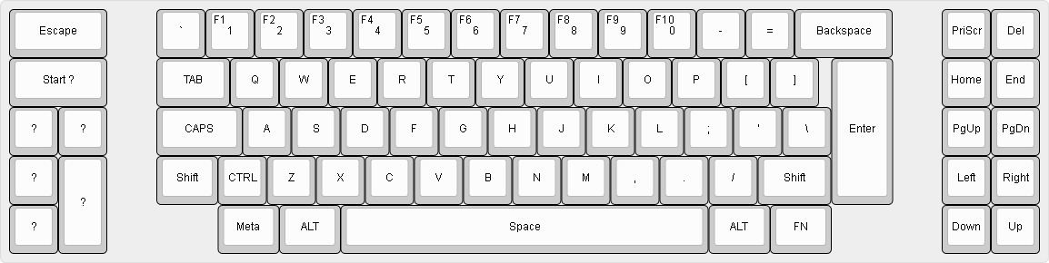
Very basic layout. Function layer only for function keys for now.
Of course as time goes on I will fine tune it.
Everything compiled fine on Windows machine. But I was unable to actually flash it.
After an hour of trial and error, searching for solutions. I gave up, put the damn thing on the thumb drive and went to the basement, where linux server is located. Flashed the contoller, went back up to test and... it didn't work

Checked the code couple times for errors... everything seems alright.
Checked the diodes and all connections on the board and controller. Everything seems fine. What the hell?
Turns out forcing NKRO in
config.h makes the whole board unresponsive.
Which I did. Don't know why tbh, probably because it is there as an option
But out of curiosity anybody knows why this happens?
Either way the board works now as it should.
Still TODO:
1. Mounting controller to the case.
2. Designing and ordering the bottom.
3. Paint job.
4. Cable managment.