Converting Zephyr stackpole board, can it be done?

User avatar
Redmaus
Gotta start somewhere

25 Jun 2019, 01:22

I got this Zephyr stackpole board from Computer Reset, and I'd like to convert it to USB using a pro micro and soarer's converter.
Spoiler:
o8VNa54.jpg
o8VNa54.jpg (346.38 KiB) Viewed 3730 times
1KPlUGK.jpg
1KPlUGK.jpg (322.17 KiB) Viewed 3730 times
nIPOi4T.jpg
nIPOi4T.jpg (216.46 KiB) Viewed 3730 times
UHgIVIw.jpg
UHgIVIw.jpg (255.88 KiB) Viewed 3730 times
vBU1EnN.jpg
vBU1EnN.jpg (132.21 KiB) Viewed 3730 times
So here is the sucker on my work desk, ready for dissection.
0E2A6164.JPG
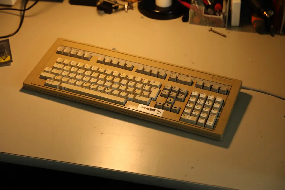
0E2A6164.JPG (155.89 KiB) Viewed 3730 times
0E2A6165.JPG
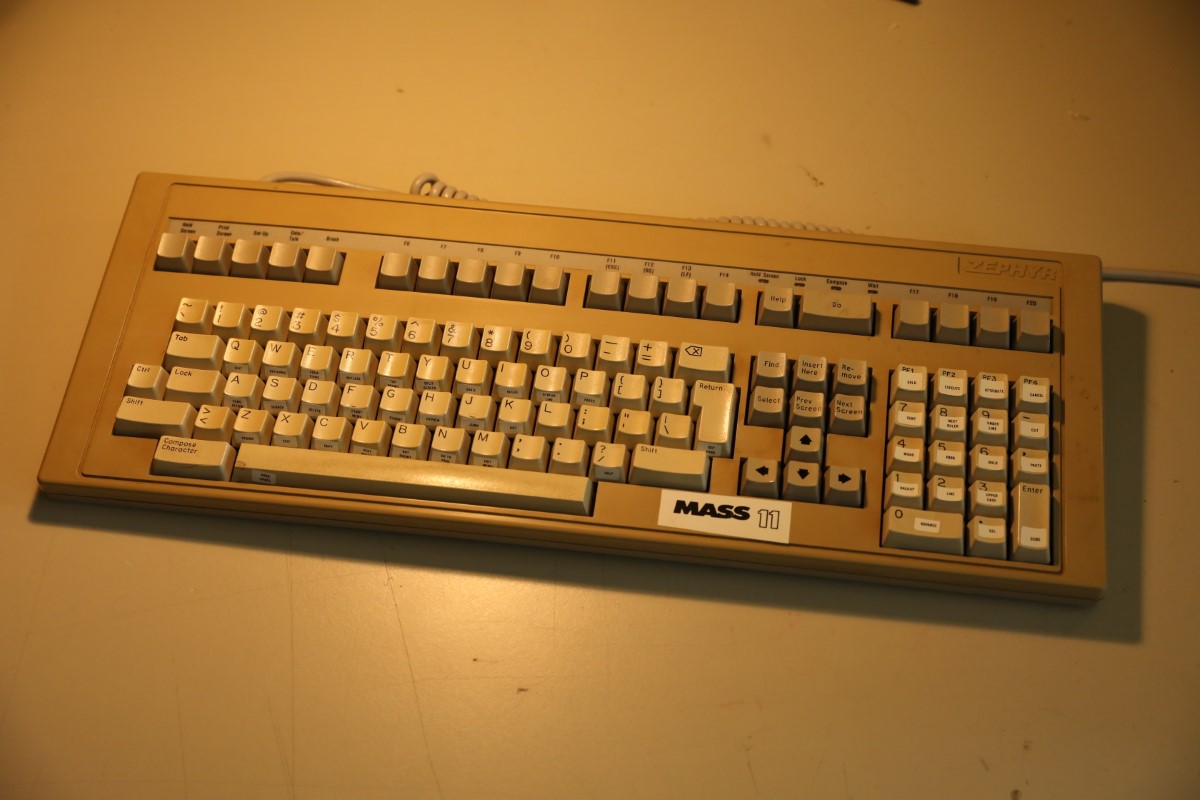
0E2A6165.JPG (156.16 KiB) Viewed 3730 times
Easy peasy, four screws around the edge of the case. Plus four little pry tabs on the two sides of the case.
0E2A6166.JPG
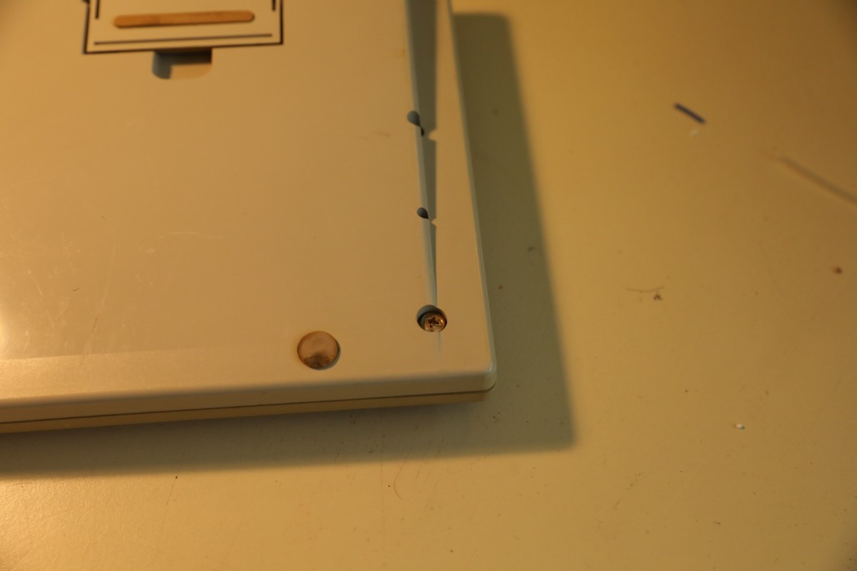
0E2A6166.JPG (84.23 KiB) Viewed 3730 times
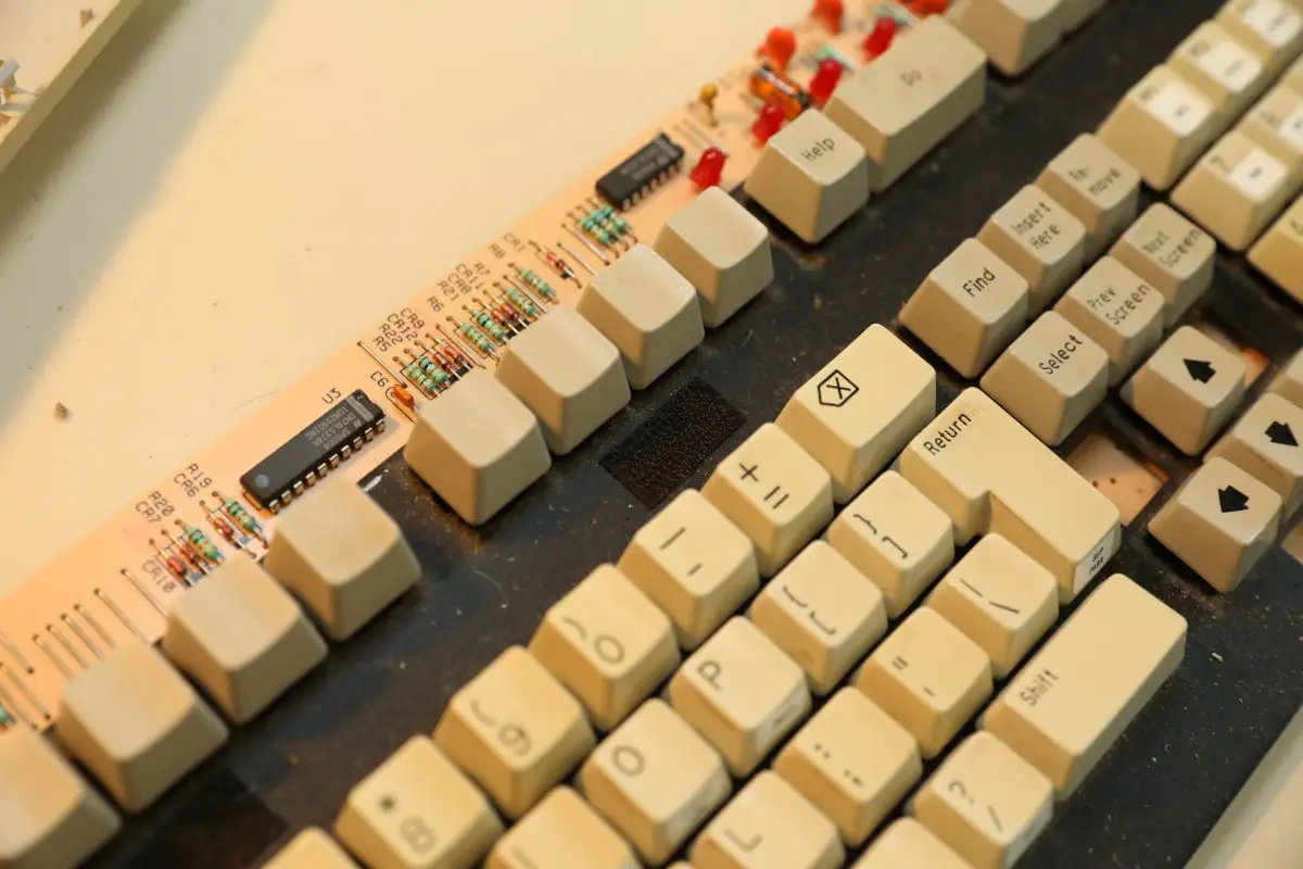
Got it open, you can see the sexy PCB below
0E2A6167.JPG
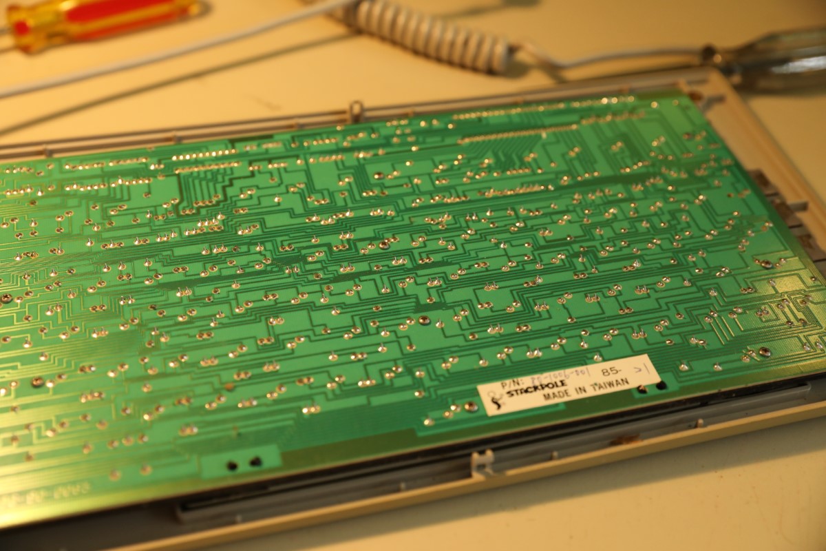
0E2A6167.JPG (228.99 KiB) Viewed 3730 times
Turns out, for once forcing the thing open was the right call. It had these peculiar velcro strips holding the plate to the case.
0E2A6168.JPG
0E2A6168.JPG (182.85 KiB) Viewed 3730 times
0E2A6169.JPG
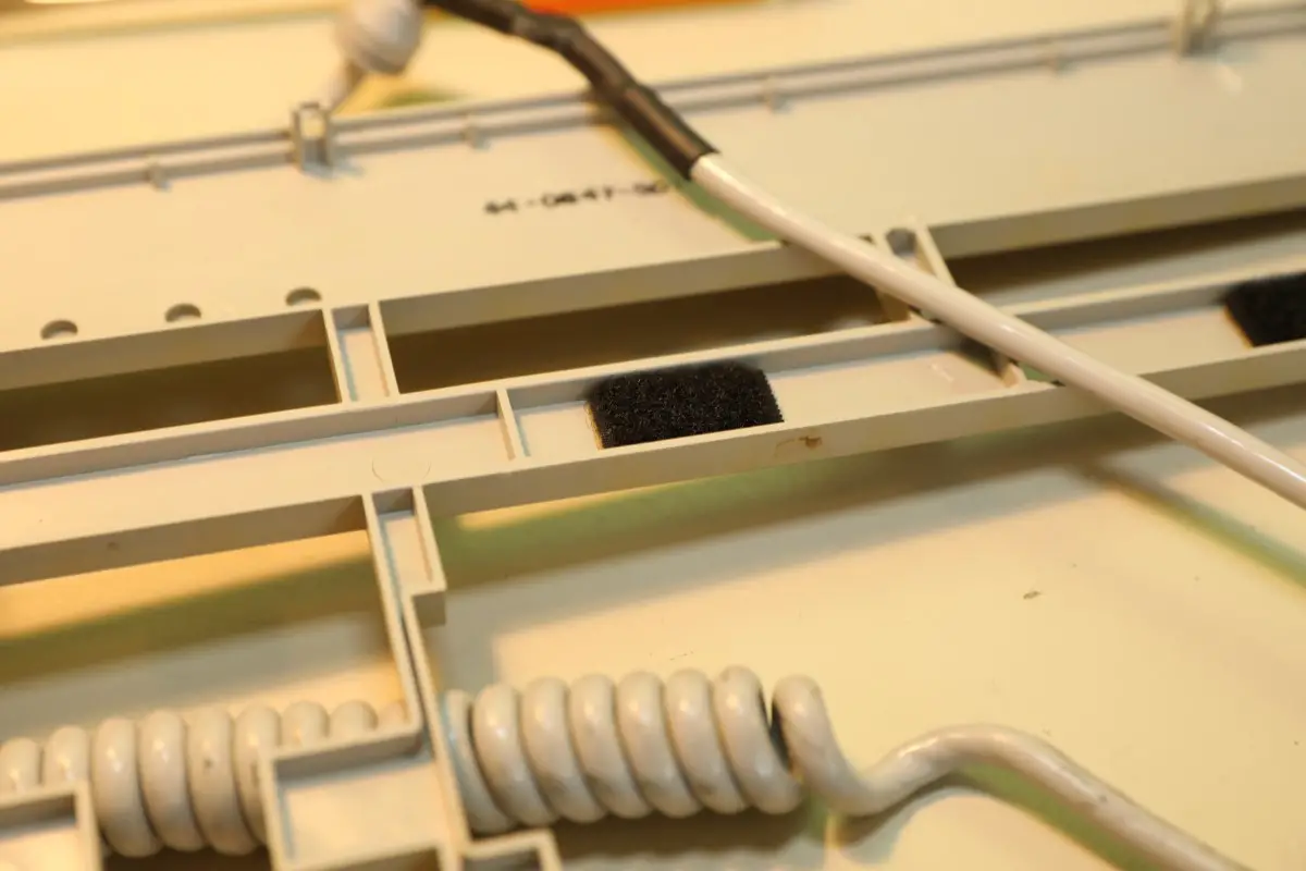
0E2A6169.JPG (128.98 KiB) Viewed 3730 times
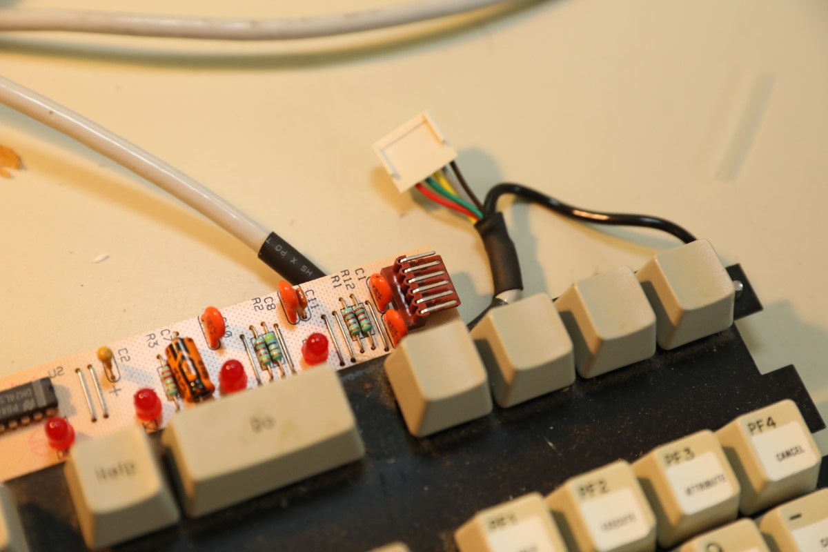
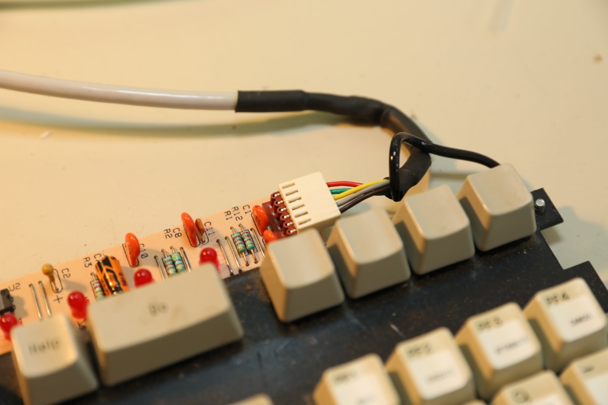
The connector, with six pins and five wires.
0E2A6170.JPG
0E2A6170.JPG (142.11 KiB) Viewed 3730 times
0E2A6171.JPG
0E2A6171.JPG (123.6 KiB) Viewed 3730 times
Here is the DIN plug:
0E2A6172.JPG
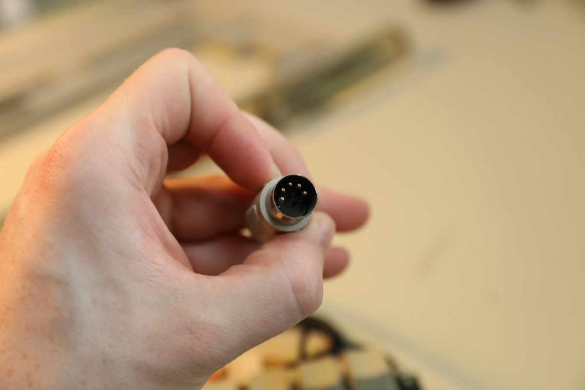
0E2A6172.JPG (92.46 KiB) Viewed 3730 times
And back of the PCB:
0E2A6173.JPG
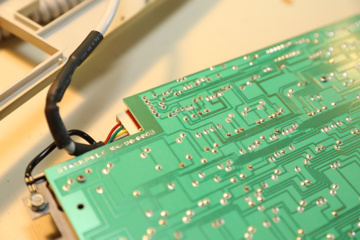
0E2A6173.JPG (186.28 KiB) Viewed 3730 times
0E2A6174.JPG
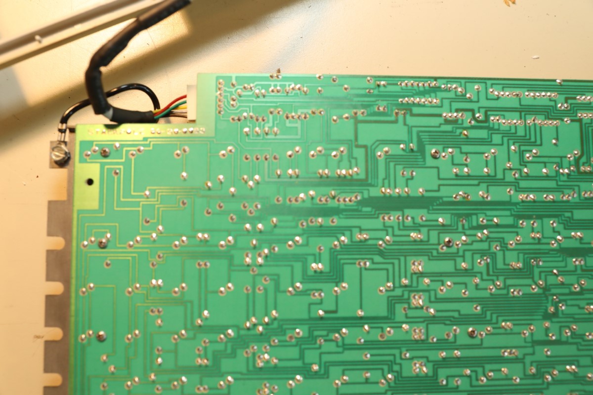
0E2A6174.JPG (209.59 KiB) Viewed 3730 times
So, how do I figure out which wire is clock, data, power, and ground? I already have a pro micro ready to be flashed with soarers firmware, which I have done before. I have not done this for a long time and even though I recently made a Wyseverter, those pinouts are already covered and fairly easy to do on your own.

I have a multimeter, would that be the best way to determine which pins go to what? Any help with this would be very much appreciated.

User avatar
zrrion

25 Jun 2019, 02:17

kbd_connector_ps2.png
kbd_connector_ps2.png (7.39 KiB) Viewed 3707 times
This should tell you where the pins are on the cable. If you want to make an external converter you can wire up something to connect to the pins as the appear in the pinout. If you plan to do an internal converter you would do a continuity test on the din plug and the connector on the board to determine what goes where. This board looks like it has uses all 5 pins, so it might actually use the reset pin, which soarers does not deal well with IIRC, so you might need to set it up with whatever Hasu's converter is. I don't know anything about that so I can't really advise on what you would need to do for that.

If you want to know what I would do if I were doing an internal converter for this check below:
Spoiler:
  • Follow the traces from the cable connector back to something else that you can solder to and solder from those pads to your controller.
  • Carefully cut the traces that lead to the cable's connector so that it is isolated completely from the rest of the board. Make sure to keep track of what pins go to what colored wire on the OG cable.
  • Take a short mini USB cable (or whatever your controller uses) and cut it open.
  • Solder the 4 wires inside of the USB cable to the pads for the cable connector on the board such that the colours of the USB cable's wires and the colours of the OG cable match up. You can ignore whatever grounding/shielding the USB cable has, it should not effect operation.
  • You can get USB ends that you can solder to and then crimp onto cables. If you don't have one of those you can get them by cutting open existing USB cables. Since you have already cut open a cable for a previous step, you likely have a USB cable you can use, but I would recommend getting loose ones. They are easier to work with.
  • Cut the end of the OG cable off and slip a short piece of shrink tube over the cable.
  • Wire the correct wires to the USB plug that you have. (if you are using the plug from the other end of your micro USB cable, you can just match the cable colours, if you are using a fresh one you might need to look up the pin-out.)
  • Crimp the two metal halves of the USB plug together with the insulator of the cable between them. This will create a strong connection that prevents the cable from breaking.
  • Push and shrink the shrink tube over both the metal plug and the cable itself, and let that cool.
  • If it does not work when you plug it in you can either desolder the wires from the micro USB and reposition them, or you can pull the wires out of the connector on the OG cable and rearrange them, you'll need a paperclip or something to push on the retaining piece to get them to come out without damaging them.
Once all that is done you should be able to plug in the USB-ified OG cable and flash whatever you want onto the controller. I like doing internal conversions this way because it allows me to reuse the original cable, I hate internal conversions that just have a dinky cheapo USB coming out from where a nice coiled cable used to go.

User avatar
snacksthecat
✶✶✶✶

25 Jun 2019, 02:17

You should try making Soarer's Simple Logic Analyzer

That'd allow you to tell Data / Clock.

But that's assuming it's AT/XT or something similar. It might be a different protocol all together. But that simple logic analyzer is definitely a good starting place.

User avatar
Redmaus
Gotta start somewhere

25 Jun 2019, 03:19

Well I wired it up with this external converter but to no avail. Keyboard lights up but I have nothing from HID listen.
0E2A6175.JPG
0E2A6175.JPG (142.72 KiB) Viewed 3689 times
On a separate note, I tried converting one of the IBM compatibles to USB with a soarers and got an R05 error. The IBM compatible board uses the same plug and I matched the pinouts right. The lock LED's light up but I only get that R05 error for the IBM compatible.

Also, this is the firmware I used:
https://geekhack.org/index.php?topic=17458.0

That is what I should be using right?

Also for the AT IBM compatible(not the Zephyr) I get this output in HID listen:
Capture.PNG
Capture.PNG (3.76 KiB) Viewed 3680 times

User avatar
Redmaus
Gotta start somewhere

25 Jun 2019, 08:34

No way this works! Turns out I had one of the connections wrong, ground is not black on that AT to PS/2 adapter i sliced up, its green!
I have no clue why this would be, but it turns out everything works now! Feels good to be typing on such a beast even if the layout is atrocious. Thanks for all the suggestions, turns out you just need to think hard and retrace your steps.

Also, the R05 error basically means the clock is timing out. Makes sense considering clock was ground. :roll:
I typed that whole message out on the stackpole Zephyr and even though the switches aren't too shabby I don't like this layout one bit, I missed shift far too many times :lol:

kmnov2017

25 Jun 2019, 11:42

Redmaus wrote:
25 Jun 2019, 08:34

I have no clue why this would be
That's because manufacturers don't really follow a specific standard. The only way to accurately tell what cable is what, is to trace the leads to the pins using a multi-meter.

User avatar
hellothere

10 Oct 2020, 00:02

I'm necro'ing this. I bought this keyboard from Redmaus a little while ago. Because it's cool. It also has been cleaning up very nicely.

* I do not have a multimeter.
* I have some idea of what a multimeter is, but I have no idea how to determine which line is for data, VCC, etc.
* I don't know who Continuity is and why he's on or in my keyboard.
* I have built a Soarer's Converter before.
* I have basic soldering and desoldering skills.
* Soarer's Simple Logic Analyzer isn't simple, to me, at least.
* Redmaus doesn't remember/know what the pinouts were.

So, could y'all please help me out? While I definitely would like the quick fix of, "Put this cable here. Solder that," I'd like to know how to determine all of this for myself.

Thanks!

User avatar
Redmaus
Gotta start somewhere

10 Oct 2020, 08:47

Well if you know the pinout to make an external AT plug soarer converter I think it will work on this keyboard.

User avatar
hellothere

10 Oct 2020, 15:55

I'll give it a shot. I did try AT adapter -> PS/2 adapter -> Active USB adapter and that didn't work.

User avatar
hellothere

11 Oct 2020, 02:38

It's mocking me.

I had it working for about two minutes, then the Pro Micro fell off my desk, ripping out the wires. I couldn't figure out which ones they were :(.

I tried using the 5-pin din section of a female AT to PS/2, as in the above example. I tried using Zirron's schematic and that didn't work for me. I do not have the "PE" wired up to anything, though. On my XT, I have an identical Pro Micro, and also no connection for PE. Looking up what PE means, as a wiring term, I see it's supposed to be for "Protective Earth." Further, it's supposed to be "ground." So, wire it with two grounds?

Post Reply

Return to “Workshop”