Custom Trackball

User avatar
wcass

02 Jan 2013, 06:18

So I am working on a DIY trackball. It’s coming along nicely, but I could use some suggestions (see bullets at the end).

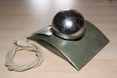
I am using a 52.5mm snooker ball because these are a good size, inexpensive, and available in many colors; but it should also work with any hard smooth ball from 50 to 70mm with only minor modification. If you wanted to do something similar, you could use any billiard ball or find some very nice “gemstone” spheres on eBay.

My trackball stand is made from a 2” PVC male adapter, a 2” knockout plug, and a 2” female adapter. I got all three from the local hardware store for under $5 – the first two from plumbing, the third from electrical because it screwed completely onto the male thread where the plumbing female got tight about half way on. I also ordered a package of .125” silicon nitride bearings from eBay.

The first thing I did was to trim the lip of the knockout plug and cut the slip parts of the male and female adapters off. The plug should fit at the bottom of the threads of the female adapter and the two adapters should screw together with the rim of the inner part (male) just capping the outer and the outer part (female and cap) capping the inner.
1-materials.JPG
1-materials.JPG (168.87 KiB) Viewed 17429 times
Next, I made a paper template of an equilateral triangle inside a 2” circle to mark the location for three bearings on the top of the male adapter and very carefully drilled about .1” deep with a .125” bit. I inserted the silicon nitride bearings and tested the spin. My Kensington Expert Mouse ball spins better in this stand than in the one made for it. The snooker ball does not spin quite as freely as but still better than many trackballs I have used. The bearing holes are tight enough that the bearings do not fall out even when the stand is inverted.
2-adapters.JPG
2-adapters.JPG (115.35 KiB) Viewed 17429 times
The knockout plug is used as a platform to mount an optical sensor. The optical sensor I have used so far is an Apexone A2637B that I pulled from a cheap USB/PS2 mouse. I had to fit it inside of a 1.9” circle, so I just hacked off the switches and scroll wheel. It fits, but the location of the sensor is not ideal.
3-sensor.JPG
3-sensor.JPG (141.69 KiB) Viewed 17429 times
The knockout plug is placed inside the female adapter and screwed onto the male adapter to the point where the distance to the ball is correct for the optical sensor. This feature should allow the stand to work with a range of ball sizes but you may need to reduce the threaded length and depth of the adapters. It also can be used to lock the trackball into a 2.5” hole on a case that might have L/M/R switches or scroll wheel mounted also.
4-LED.JPG
4-LED.JPG (120.52 KiB) Viewed 17429 times
5-assimbled.JPG
5-assimbled.JPG (139.81 KiB) Viewed 17429 times
6-top_fit.JPG
6-top_fit.JPG (107.07 KiB) Viewed 17429 times
7-bottom_fit.JPG
7-bottom_fit.JPG (117.01 KiB) Viewed 17429 times
So these are my issues:
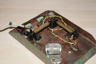
• Ideally the sensor “eye” should be at the exact center bottom of the trackball, but due to the size of the lens and PCB that is not possible. I’m thinking of making my own PCB (the mouse chip uses just 3 caps, two resistors, and LED) and using a modified lens (perhaps from a DVD drive). Your thoughts?
• A trackball is a mouse turned upside down, so either the X or Y axis must be flipped on the sensor depending on the way the sensor was turned over. This can be done with an app (SakasaMouse), driver (MAF-Soft Mouse), or mouse firmware. I would like to go firmware, but I don’t think my chip supports it and know I don’t have the skills. Suggestions?

jeff

02 Jan 2013, 12:47

Great job! I tried a few years ago with an old ball-mouse but it was not really usable. You acheived a very simple and clean solution.

To aligne the center of the captor I would first try to angle the PCB 30° in the box. If not enough room maybe a hole in the grey adapter to shift the PCB, not clean but for 5$ it may worth a try. By the way, I'm not sure a PCB of your own would save some space because the alignment LED-mirror- chip must be preserved. Maybe using a smaller LED?

Firmware modification doesn't seem to be possibe http://www.ic-jiazhi.com/upload/PDF/A2639_E.pdf. If you already have a teensy in you keyboard, just connect your trackball to it as a ps2 device, you could then change the orientation as wanted. http://www.pjrc.com/teensy/td_libs_PS2Keyboard.html or http://www.practicalarduino.com/project ... d-or-mouse. Otherwise driver solution looks better because low level but I never tried.

You may have a look here http://traqball.blogspot.fr/, it may inspire you.

Keep on

User avatar
uberben

02 Jan 2013, 18:07

Very interesting. I will definitely be considering this for my keyboard mod.

User avatar
wcass

03 Jan 2013, 06:08

Thanks, jeff for the ideas and link. Flipping an axis with a Teensy is a great idea, but again i don't have the programming skills. Maybe Soarer, Hasu, or another member of our community could be interested enough to lend a hand.

I'm not sure I completely understand your suggestions about aligning the PCB. Angling the PCB would require suspending the ball higher - something i don't want to do as it would limit the case options to something taller. And I don't think that the LED mirror has to be preserved because one of the other mice i disassembled for this was a "finger mouse" that uses the same chip but a very different lens. That mouse manages to fit all but one cap on a PCB not much bigger than the sensor chip.
fingermouse4-sm.JPG
fingermouse4-sm.JPG (151.03 KiB) Viewed 17320 times

User avatar
riffraff

30 Jan 2013, 07:13

So do the bearings actually move at all or does the trackball sort of glide on them?

Very simple design :)

jeff

16 Mar 2013, 12:04

Wcas : I found back the trackball I made 13 years ago from a PS2 mouse, at a time when optic mouses were not very common. It works but it's really unusable...

Image Image

No problem for X or Y flip, just need to know on which side of the wheel the detector must be put.

Once again, really like your snooker and plumbing solution.

User avatar
uberben

25 Apr 2013, 16:33

I've been thinking of doing a mod like this for my Kinesis. Yesterday I found this on Tindie: https://www.tindie.com/products/jkickli ... er-sensor/

The guy designed the board for a custom trackball, and it works over SPI, so it should be relatively easy to integrate into a custom keyboard controller (as I have planned).

User avatar
Peter

25 Apr 2013, 17:49

Sorry I missed this !
That is really a nice DIY-project !!

bester42

23 May 2013, 23:54

Many cheep optical mouse seem to have a sensor with fixed focus lens. If you change the focus to a longer distance by removing the lens or using an extra lens, you should be able to allign the sensor tangential insted of vertical to the ball. In the place the sensor normaly would be, you place a 45 degree mirror - so the sensor "looks" via mirror on the ball - which meens one axis is changed optical insted of electrical or microcontroller or software.

I have not tested it yet - and also it may be a space problem. On the other side, only the mirror have to be placed unter the ball, if you make the focus distance long enough it may even be helfull to solve space problems. A mirror to solve a mirror-problem was just a solution jumping in my brain while reading your post. Maybe it is helpfull.

Post Reply

Return to “Workshop”