Page 2 of 2
Posted: 07 Jun 2013, 21:46
by 7bit
Soarer wrote:7bit, I want proof that you a can build a keyboard... can you show me one that you've built?

edit: it must actually work, btw!
I don't need to actually build it. I only need the components and a method to put them together.
For example one method to put them together is to ship all the necessary components to Half-Saint. By magic, it will return back to me in an assembled state.
It is like compiling a program from source code using all necessary libraries, rather than coding the machine code all buy yourself.
If I could buy my dream keyboard readily made, I'd do so.
Posted: 07 Jun 2013, 21:48
by 7bit
Halvar wrote:Soarer, you infuriated 7bit by suggesting a cheaper solution in his GB thread. That's threadcrapping, and he doesn't
like that!
No,no, it is not the point! I love thread crapping. I do this myself in my own thread as you can see, but I don't like if people vaguely suggest things and don't tell me the complete solution.
Posted: 07 Jun 2013, 21:52
by Soarer
Well then I'll rephrase the question...
I want proof that you a can design a keyboard... can you show me one that you've designed (circuitry, PCB, everything), that has been built (don't care who builds it), and which works?
As for the libraries analogy... why ask me for details when all you want to know is the abstract, which I gave?
Posted: 07 Jun 2013, 22:07
by 7bit
The design is trivial except for the traces.

I start when Round 4 is really over.
Posted: 07 Jun 2013, 22:18
by Soarer
Well then seriously now... how much 'detail' do you need?
This function - a "4 to 16 line decoder" (google it) - can be built with one or two chips, but two is a lot cheaper...
Code: Select all
from 4 pins on CPU ------ to 16 matrix column strobes
                  |      |---- 1
                  |      |---- 1
                  |      |---- 1
                  |      |---- 1
                  |      |---- 1
                  |      |---- 0     one active column strobe at a time
            0 ----|      |---- 1
binary      1 ----|      |---- 1
code        0 ----|      |---- 1
            1 ----|      |---- 1
                  |      |---- 1
                  |      |---- 1
                  |      |---- 1
                  |      |---- 1
                  |      |---- 1
                  |      |---- 1
                   ------
That's all it is, a simple circuit.
Posted: 07 Jun 2013, 22:27
by 7bit
OK, so I connect that magic thing between keyborad PCB and teensy PCB and on one side the PCB thinks it is connected to a teensy++ and everything is good, so user can type without care. And teensy thinks it is a PCB with only a tenkeyless layout connected which has one extra modifier key which tells the teensy to look into a different table. That magic thing sends one time the signals of one half of the keyboard PCB and the other time the signals of the other half of the PCB.
Right?

Posted: 07 Jun 2013, 22:42
by Soarer
Not quite half and half... you know how a matrix is, say, 16 columns by 8 rows? And that scanning it involves driving each column (usually low) in turn and reading the rows? Well, this drives the columns. Teensy code still thinks it has a full size 16x8 matrix. It's just that when Teensy wants to drive a particular column, instead of driving one pin out of 16 and switching off the rest, Teensy drives 4 pins with the number of the column it wants to drive.
Posted: 07 Jun 2013, 23:01
by matt3o
Muirium wrote:Anyway, what's the controller to use if you want LED back lights under every key in the board? You hook up the LEDs into a similar matrix to the switches, so I gather. But what chip is well suited to controlling those?
as far as you have enough pins, any controller will do. If you put all LEDs together (on/off) you just need 1 pin.
Posted: 07 Jun 2013, 23:05
by Halvar
Although I'm sure that's both possible and cheaper than a Teensy++, like you said in your first post, Soarer, the price difference doesn't seem to be worth it. Great thing about the Teensy++ is that can work as a complete programmable keyboard controller, rather than needing a second part of the controller in the form of one or two additional ICs that I have to put somewhere on a PCB. With the Teensy++, I can essentially build my whole keyboard from the Teensy++, some wire, some switches and some diodes. Maybe some resistors and some LEDs if I want them. I dont even need a PCB at all if I have a plate for the switches.
Posted: 07 Jun 2013, 23:26
by Muirium
matt3o wrote:Muirium wrote:Anyway, what's the controller to use if you want LED back lights under every key in the board? You hook up the LEDs into a similar matrix to the switches, so I gather. But what chip is well suited to controlling those?
as far as you have enough pins, any controller will do. If you put all LEDs together (on/off) you just need 1 pin.
All right!
But is there a Teensy (or the like) with enough pins to control both a full matrix of switches and individually switched LEDs for an entire keyboard?
Posted: 07 Jun 2013, 23:55
by Soarer
Halvar wrote:Although I'm sure that's both possible and cheaper than a Teensy++, like you said in your first post, Soarer, the price difference doesn't seem to be worth it. Great thing about the Teensy++ is that can work as a complete programmable keyboard controller, rather than needing a second part of the controller in the form of one or two additional ICs that I have to put somewhere on a PCB. With the Teensy++, I can essentially build my whole keyboard from the Teensy++, some wire, some switches and some diodes. Maybe some resistors and some LEDs if I want them. I dont even need a PCB at all if I have a plate for the switches.
Aha! That price comment was about this thread, as much as any way to make it cheaper! Scouting around for a €1 saving, when there's $8 to be had... which still isn't a lot compared to whatever the cost of the full kit will be, granted.
I would agree with your other points if this was for controller
replacement, but this is for a designed PCB - so adding a couple of chips is trivial (for a competent designer
). They can be non-surface mount ones, so no problem with assembly either.
Posted: 08 Jun 2013, 06:59
by jpatters
7bit wrote:OK, so I connect that magic thing between keyborad PCB and teensy PCB and on one side the PCB thinks it is connected to a teensy++ and everything is good, so user can type without care.
Nothing magic about it. If you are using a device with 16 I/O lines, and it can only have one of those lines activated at a time, then there are 16 possible I/O states. If you can have more than one line activated at a time, then you only need four I/O lines to get 16 states (2^4 = 16). The decoder simply de-multiplexes the four lines to 16, because the physical nature of the keyboard matrix requires that you have only one line activated at a time. If your controller strobes the columns of your matrix, and then reads the rows, and you have more rows then controller I/O lines left over, you will need another chip to go the other way, and multiplex the many row signals to the fewer I/O lines of your controller. This will work as long as "fewer" is more than log base 2 of "many".
Posted: 08 Jun 2013, 08:48
by matt3o
Muirium wrote:matt3o wrote:Muirium wrote:Anyway, what's the controller to use if you want LED back lights under every key in the board? You hook up the LEDs into a similar matrix to the switches, so I gather. But what chip is well suited to controlling those?
as far as you have enough pins, any controller will do. If you put all LEDs together (on/off) you just need 1 pin.
All right!
But is there a Teensy (or the like) with enough pins to control both a full matrix of switches and individually switched LEDs for an entire keyboard?
if you need a 1:1 LED matrix you probably need the same config as for the switches (so 15+5 for switches and 15+5 for LEDs). Teensy++ should work by a whisker for a 60%
Posted: 08 Jun 2013, 10:46
by Muirium
Thanks Matteo. I've got to guess the Teensy++ is too big for the space bar spot in the Steely / Brownfox design, but it's good to know one chip can handle all the logic. I might investigate this later.
Of course, I'd probably have a lot more work to do as there isn't a ready-made LED controller software kit like there is for the switches. And I'd have to insulate two overlapping matrices from each other! But feasibility is a start.
Posted: 08 Jun 2013, 12:03
by Halvar
Soarer wrote:I would agree with your other points if this was for controller
replacement, but this is for a designed PCB - so adding a couple of chips is trivial (for a competent designer
). They can be non-surface mount ones, so no problem with assembly either.
Yes, you're right, I have to admit I was thinking about what I would do with a teensy++, not so much about the Hyper project.
Posted: 08 Jun 2013, 18:35
by kps
matt3o wrote:if you need a 1:1 LED matrix you probably need the same config as for the switches (so 15+5 for switches and 15+5 for LEDs). Teensy++ should work by a whisker for a 60%
You can share the rows
or columns (depending on how much duty cycle you're willing to give up) for 15+15+5 or 15+5+5.
Posted: 08 Jun 2013, 18:53
by Soarer
"Any sufficiently advanced technology is indistinguishable from magic"... to a more primitive being

Anyway, I deliberately drew it as a 'magic black box', because there's a choice of chip(s) that can be used to build it.
The 74159 has exactly the right function, but it's not common, relatively expensive (£3+), and as large as a Teensy.
Two 74138 chips would also work neatly, but they don't have open-collector outputs.
Two 74156 chips would work well, but require an extra pin on the Teensy to select between the two chips (not a problem; you'd still be saving 11). They cost 27p each (
Farnell) when buying 100.
Open-collector outputs are better for keyboards since it doesn't matter if you short the outputs together (by accident, or mistake when building).
So the pair of 74156 chips would be my choice. Software still sees it as a matrix with 16 column strobes, and to activate a strobe it writes 'column number + 8' to five logically adjacent pins on a port (e.g. PD0 to PD4). The '+ 8' is there to drive the selection lines (e.g. PD3 and PD4) correctly for the two chips.
Posted: 08 Jun 2013, 19:12
by 7bit

Ah! the magic things get a real name and a real shape.
Now, things are much clearer!
However, I need:
- footprint for kicad
- a scheme which shows how to connect things
- a £-proxy
Posted: 08 Jun 2013, 20:14
by Soarer
I'm sure you could find a local supplier at a similar price. edit: Just how lazy are you?! 'Change Country' on the link I gave and select Germany
http://de.farnell.com/texas-instruments ... dp/1470807
DIP-16__300 or DIP-16__300_ELL (elliptical pads).
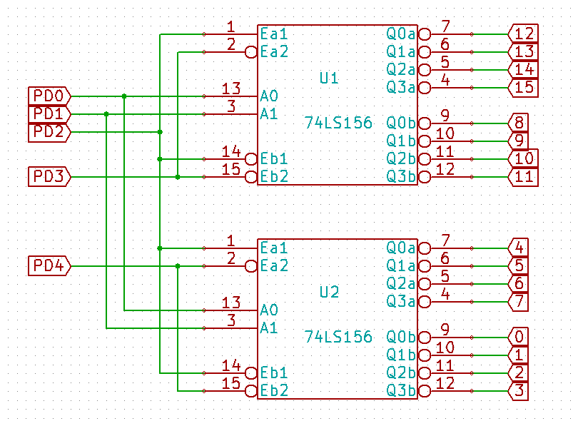
- decoder_5_to_16.png (17.28 KiB) Viewed 4694 times
See, it's really simple!
An 'activated' output is 0V, so yours diodes' stripy ends should point this way!
Expected input binary code on PD4..0 is between 8 and 23, which will activate a single output (code - 8).
Code < 8 will activate 2 outputs (code and code + 8). Not useful, but harmless!
Code > 23 will activate no outputs.
I think that's correct... I would test on a breadboard first. Not sure if I have any '156...
Schematic...
Posted: 08 Jun 2013, 21:02
by 7bit
I'm not lazy, just don't have the time to do all the research.
Please upload the file in ZIP, GZIP, BZIP2 or plain 7bit ASCII.
Thanks.
7bit.
Posted: 08 Jun 2013, 21:05
by Soarer
Please climb off that high but decrepid horse and get a rar unpacker
Posted: 08 Jun 2013, 21:30
by 7bit
Muito obrigado!!!
edit:
LOL!!!!
Why are you using this RAR-comression thing?
2002 decoder_4_to_16.tar.bz2
2012 decoder_4_to_16.tar.gz
2141 decoder_4_to_16.rar
2304 decoder_4_to_16.zip
6174 plain text
Posted: 08 Jun 2013, 21:53
by Soarer
Because I don't have "Add to decoder_4_to_16.TAR" on my context menu
Posted: 09 Jun 2013, 01:03
by dondy
7bit wrote:I'm not lazy, just don't have the time to do all the research.
Please upload the file in ZIP, GZIP, BZIP2 or plain 7bit ASCII.
Thanks.
7bit.
http://www.7-zip.org/ one would really expect you to use it... like, really.
(unrar is also available for most linux distributions, though it might be packaged in a non-free repository)
Re: AW: Teensy++ controller in Europe
Posted: 09 Jun 2013, 03:10
by ne0phyte
7bit wrote:
Please upload the file in ZIP, GZIP, BZIP2 or plain 7bit ASCII.
7bit.
Why not install unrar? (everyone should have that anyway)
It would have been faster for you to install that than for Soarer to repack and upload it again...
Posted: 09 Jun 2013, 03:49
by Soarer
decoder_4_to_16.rar ... Downloaded 5 times ...
decoder_4_to_16.zip ... Downloaded 1 time ...