Page 1 of 1
Replacing a broken cable - how?!
Posted: 08 Oct 2015, 15:20
by Chyros
Time to dig into this again. I mentioned this briefly a while ago but it was clear I needed a new cable and a multimeter to do this. I managed to find a cable that fits into the connector and which has the same metal screwable loop (presumably a ground) from some board I slaughtered ages ago, and I borrowed an antiquated multimeter from the mechanical workshop, so now I'm ready to go.
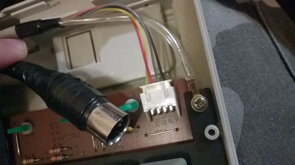
It regards my Focus FK-2002 which has a connector that every once in a while seems to fail, so the keyboard stops registering. It generally works fine, but it's unreliable and that's kind of a deal killer - a shame for such a nice keyboard (especially one in otherwise such an excellent condition), and it deserves being restored to proper functionality. I have to really jam the connector into the adapter (it's not the adapter) and then it works again, but it must've been a clear previous issue because the connector was taped when I got it. The connecting ring even slides back and forth a little bit.
This is the old connector:
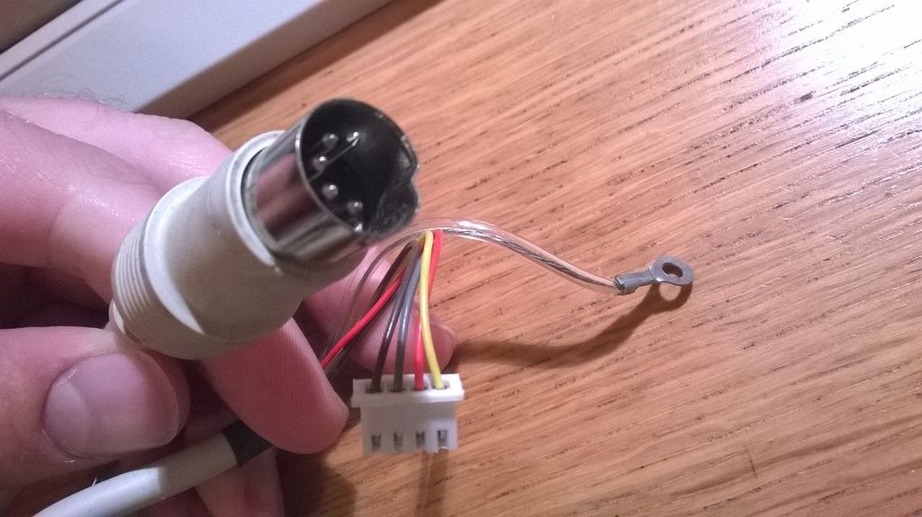
and this is the new one to replace it:
So, presumably I have to do all kinds of testing and tinkering to get this done; where do I start?

Posted: 08 Oct 2015, 15:24
by Muirium
Nah, just plug it in and see! The colours look good. But if you really want to test, draw a diagram of the DIN 5 pins and check with your meter that they go to the same colours each time. I bet they do.
Posted: 08 Oct 2015, 15:27
by klikkyklik
Muirium might be right, but I am of the cautious type, and would certainly "map" the pins to ensure that they go to the correct connector wire before plugging it in. It's fast and easy to do, so there is no reason NOT to do it.
Posted: 08 Oct 2015, 16:29
by fohat
You know that you can make a perfectly good "uni-meter" (tests only continuity) with a battery and a light bulb.
Wire them up in series with a break in the wire somewhere. Touch the 2 sides of the broken wire to the bits that you want to test, and if the light comes on, you have continuity.
Posted: 08 Oct 2015, 16:55
by Chyros
Ah, so THAT'S what those exposed bits on the female connector is for! For testing with a multimeter! Cheers guys

.
Well, just testing pin against pin is a bit easier than I thought. The BGRY connector maps out as 2435 on both connectors and the outside, cylindrical ring corresponds to the little metal loop, so it looks like the cable is completely compatible
.
I didn't expect it to be this easy! I have to do more cables for the cableless Cherry (and another cableless board I picked up from the same batch) though, and I suspect they'll be harder. So for future reference; what do I do when the connectors DON'T map out the same? It looks like I can pull out the leads with enough violence, but I'm not sure it's possible to stick them back in. Also, would a cable that maps out the same but that DOESN'T have the little metal loop on it work for this board, or do you really need the loop?
Posted: 08 Oct 2015, 17:14
by Engicoder
The loop is a protective ground/earth. It helps shield the signals from outside interference (EMI), and prevent them from generating it. It should work fine without it as long as you're not running your arc welder at the same time.
Posted: 08 Oct 2015, 17:55
by Compgeke
Rather than directly replacing cables on a board such as this it's possible to replace just the connector if you can solder. The AT connector is just a 180* 5-pin DIN and they're
fairly cheap, especially from HK.
When it comes to rearranging pins on the internal side, you have to use a paperclip or something to release some barbs\clips to pull those pins out. While it is doable, I've found it easy to screw up the connector making it where those pins never stay in place properly. It is doable, just don't rush yourself.
For the Cherries soulman said he's thinking about pulling the pinout off a working cable he's getting and using the original cut cable to hack onto a USB to PS/2 keyboard and mouse adapter. He goes into more detail
here.
Posted: 08 Oct 2015, 18:35
by XMIT
Always check the pins directly by testing for continuity to a known chip like the Intel 8048 (a common controller chip). You really don't want to confuse power and ground. There is no standard for how the pins of the AT connector are routed internally.
Posted: 08 Oct 2015, 20:37
by Chyros
XMIT wrote: Always check the pins directly by testing for continuity to a known chip like the Intel 8048 (a common controller chip). You really don't want to confuse power and ground. There is no standard for how the pins of the AT connector are routed internally.
I don't follow. If the pinout in the cables are the same, are there other factors that can screw it up then? Oo
Posted: 08 Oct 2015, 21:01
by Engicoder
Chyros wrote: XMIT wrote: Always check the pins directly by testing for continuity to a known chip like the Intel 8048 (a common controller chip). You really don't want to confuse power and ground. There is no standard for how the pins of the AT connector are routed internally.
I don't follow. If the pinout in the cables are the same, are there other factors that can screw it up then? Oo
I think he is saying that the order of the pins on the PCB doesn't mean anything. You probably want to follow those pins back the controller to verify power and ground.
Posted: 08 Oct 2015, 21:05
by XMIT
Engicoder wrote: I think he is saying that the order of the pins on the PCB doesn't mean anything. You probably want to follow those pins back the controller to verify power and ground.
Yes. That. The pins on the PCB may be in just about any order!
Posted: 08 Oct 2015, 21:41
by fohat
And, wait for it:
Never Trust Color !
Posted: 08 Oct 2015, 22:52
by Engicoder
fohat wrote: And, wait for it:
Never Trust Color !
You mean red and black ARE NOT power and ground
Why is it that if it has red and black wires they are almost never what they should be? When was the red/black convention first common place?
Posted: 08 Oct 2015, 23:33
by andrewjoy
Pretty much always, brown and blue are live and neutral for UK AC.
its just an engineer being an asshole
Posted: 08 Oct 2015, 23:50
by Chyros
XMIT wrote: Engicoder wrote: I think he is saying that the order of the pins on the PCB doesn't mean anything. You probably want to follow those pins back the controller to verify power and ground.
Yes. That. The pins on the PCB may be in just about any order!
Oh I wasn't measuring the pins on the PCB, just the ones on both sides of the cable. Should I have?
P.S. It works! I'm typing on it right now! Clicky click!
Posted: 08 Oct 2015, 23:53
by Engicoder
Chyros wrote: XMIT wrote: Engicoder wrote: I think he is saying that the order of the pins on the PCB doesn't mean anything. You probably want to follow those pins back the controller to verify power and ground.
Yes. That. The pins on the PCB may be in just about any order!
Oh I wasn't measuring the pins on the PCB, just the ones on both sides of the cable. Should I have?
P.S. It works! I'm typing on it right now! Clicky click!
As long as you have the original cable and match the pins at both ends of the connectors, there should be no problems, as it seems there weren't.

BTW, there is something waiting for you at the Post Office
Posted: 09 Oct 2015, 00:04
by Chyros
Engicoder wrote:
As long as you have the original cable and match the pins at both ends of the connectors, there should be no problems, as it seems there weren't.
BTW, there is something waiting for you at the Post Office
I know, I'm picking it up tomorrow
. I'm never at home so this happens frequently xD .