Page 1 of 3
Model F controllers
Posted: 14 Apr 2014, 10:37
by xwhatsit
Hello all,
Now that I have my beamsprings up and running, I really ought to do something about the couple of Model F boards I have sitting around (at least before I get distracted and try to do something about the four Selectrics that are now taking up space doing nothing).
Of course I can use Soarer's magnificent protocol converter, but I'm keen to see how well the capsense stuff I used on the beamsprings translates to the Model Fs. Also—well, it's fun.
I have both a PC-AT and a 122-key terminal board. I have pulled apart both and the question I wish to ask is:
Am I correct in saying all Model F boards (apart from the PC-XT) use the same annoying 3.96mm 30-pin ribbon cable to connect between the keyboard and the controller? Is it always soldered directly to the board and the controller?
Both my PC-AT and 122-key terminal seem to do this, and in fact seem to have an identical controller (with the same screw hole spacing), despite the very different form factor of the overall keyboard.
I ask this as it would be nice if my controller was as usable as possible across the Model F range.
Posted: 14 Apr 2014, 11:09
by Muirium
Answer: no. Dorkvader schooled me on this very topic recently:
http://deskthority.net/keyboards-f2/ibm ... it=Bigfoot
Of course, I'm interested in your Model F efforts for a little reason by the name of Kishsaver! I got mine in time for Kishmas, but besides a little testing with Hasu's converter (which is too slow to use in practice) it's been sitting, waiting, and taunting me!
Posted: 14 Apr 2014, 11:14
by xwhatsit
Ah poos so it's not just the XT. Did I understand your linked thread correctly in saying that that strange terminal board had the controller on the main keyboard PCB, as per the XT?
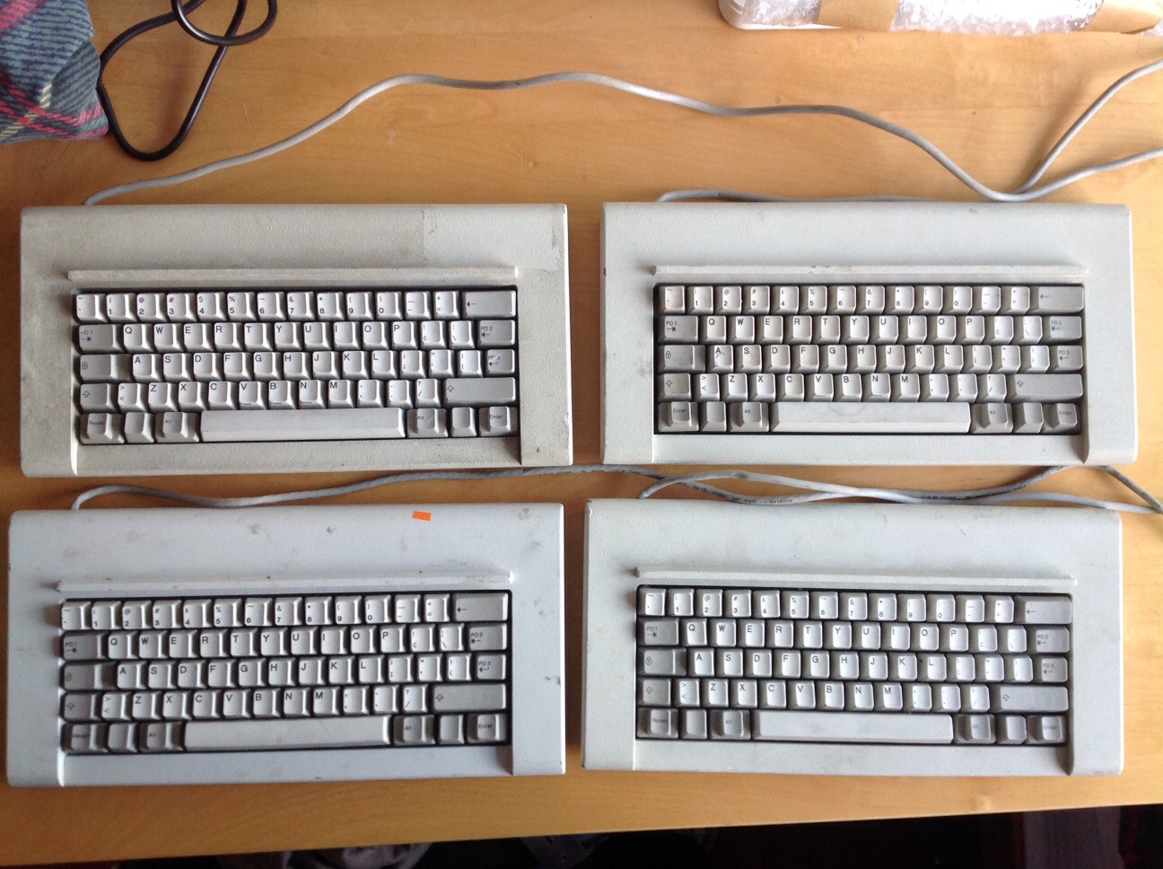
These `Kishsavers' look lovely! Are they all gone?
Posted: 14 Apr 2014, 11:17
by Muirium
Yes, alas. But I know someone who's sitting on three, if my suspicions are correct! (Not me.)
Dorkvader pointed me to this:
No sign of a header, he says, so a right bugger for replacement.
Posted: 14 Apr 2014, 12:32
by scottc
If the mysterious kish-sitter would like to sell me one, I would happily oblige...
Posted: 14 Apr 2014, 12:36
by xwhatsit
That picture, Murium, is that simply an XT-style controller-on-sense-PCB? The effect being, like the XT, to change the controller you'd have to desolder everything and run wires or hacksaw off the controller stub of the PCB and solder a new controller to the remnants.
Posted: 14 Apr 2014, 12:45
by Muirium
Apparently so. I only know what Dorkvader said the other day on the Bigfoot thread. Seems to be a bit of a non starter.
The Kishsaver, meanwhile, is no problem. I've been inside my 1986 model and confirmed this.
Posted: 14 Apr 2014, 12:51
by xwhatsit
Yeah I think it'd be a fairly major project on its own. I don't like cutting up this old gear; clean controller swapouts are one thing, but I as I've said before I feel some of this early IBM stuff (especially the beamsprings, but even many of the unusual Model F terminal boards) are more or less historical artifacts, so it's nice to keep everything intact.
I'm racing through this layout, hopefully have something ready in a couple of days. It's more or less the same schematic as the Displaywriter controller, maybe a few pin-swaps here and there. The pin-array connector (for the ribbon cable) makes the routing much easier in some respects, as does IBM having put all of the rows at one end and the columns at the other.
I'm wrestling with the idea of placing a mini-USB connector or not. As I recall space is pretty tight inside my PC-AT and even the 122-key terminal (compared to a beamspring anyway!); may just be easier having a flying-lead USB connector. God knows I've got millions of useless USB-B connectors hanging on a hook waiting to be cut up.
Posted: 14 Apr 2014, 12:56
by Muirium
Useful pictures from inside a little Kishsaver here:
http://deskthority.net/post141015.html#p141015
The replacement controller HaTaa and others are working on seems to have stalled a bit the last few months, so if you're looking for an enthusiastic beta tester…
Posted: 14 Apr 2014, 13:01
by xwhatsit
Oh cool thread! Didn't know there was another capacitive keyboard controller project going on. Looking at the photos it looks very similar to something I heard floating around at Geekhack a year or so ago (opamps, multiplexers etc.). Bit of a different approach to what I've done with my boards but should work just as well in theory nonetheless.
Those photos are pretty handy re. Kishsaver internal space. I can see there are similar concerns with space. My layout is currently looking smaller than the existing board, but might be safe to go with the flying-lead USB connector just in case.
Posted: 14 Apr 2014, 13:08
by Muirium
The Kishsaver's own fixed cable is pretty horrible, and I plan to replace it and reuse the hole in the case for something USB of my own. So internal sockets are definitely good by me.
There's also a circular hole on the bottom of the case for the volume adjustment (?) knob on the clicker's daughter board. I've no particular interest in using that, so the space could be handy. Wonder how big is a solenoid!
Posted: 14 Apr 2014, 13:32
by wheybags
scottc wrote:If the mysterious kish-sitter would like to sell me one, I would happily oblige...
As would I... :3
Posted: 14 Apr 2014, 16:07
by mr_a500
I too need a "Kishsaver". So that makes three of us and three keyboards. I suggest we get together, go beat up that guy and steal his hoarded Kishsavers. ("it's not personal, it's business")
Posted: 14 Apr 2014, 16:12
by scottc
I agree! Give us details, Mu, or the Kish gets it!
Posted: 14 Apr 2014, 16:25
by Muirium
When Tinnie sold us all his haul, I suspected the price would go up over time. Mine's not for sale (I only have one) but it's not surprising there's hoarding going on. Money talks!
Posted: 15 Apr 2014, 06:20
by xwhatsit
OK have a bit of a pickle here.
Have done the layout; however as you can see from the picture we have a lot of wasted space.
I've added the mounting holes for what I'll refer to as the `standard' Model F controller (what's in my PC-AT and 122-key terminal anyway). This leads to a chunk of wasted space on the bottom and sides. Could live with that, as we've got to mount the sucker somehow.
However, in adding mounting holes as per the smaller Kishsaver controller, we have now have wasted space on the top too.
The end result is a board 149.5mm x 42.5mm. A bit portly, and about twice the price per board from OSHPark compared to the beamsprings.
It's still smaller than the original controllers, but I don't like it.
The alternative I suppose is to have two separate boards, one for a Kishsaver, and one for a standard Model F, which only differ by mounting pattern. Or have snap-off bits, and wear the extra manufacturing cost. Or... forgo mounting holes entirely and attach it just by the ribbon cable and some nice spongy double-sided tape-foam...?

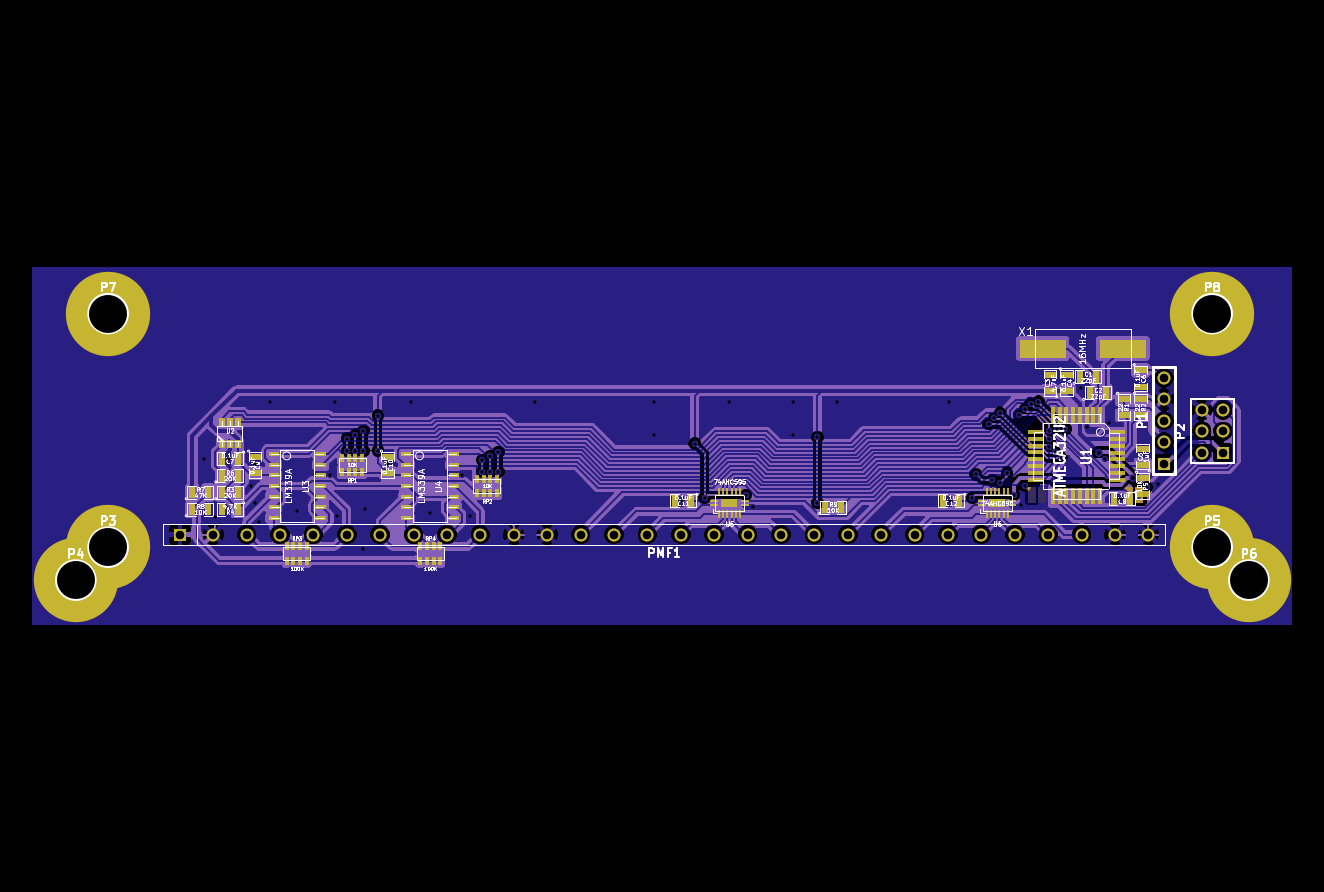
- model-f-usb.png (94.84 KiB) Viewed 10489 times
Posted: 15 Apr 2014, 07:02
by Muirium
Last option (no holes, barebones minimalist) sounds like a good prototype to me.
Posted: 15 Apr 2014, 07:06
by wcass
I for one think it is great to have more people working on a replacement controller. I have a KS and 122 also and would be happy to assist with "will it fit" questions.
Posted: 15 Apr 2014, 07:14
by xwhatsit
Cool!
I don't want to step on anybody's toes—all my stuff is open-source, so if what I do is of use to anyone else's capsense projects then anybody is welcome to take what they like

Wcass: do you think if the mounting holes were moved closer to the ribbon cable that would cause problems?
Posted: 15 Apr 2014, 07:20
by HaaTa
Sorry, I got distracted with other projects (mainly the force gauge). Work is still ongoing for the cap sense controller though.
Trying to push along a Teensy 3/ARM version (this means a redesign), which I want as a general purpose cap sense controller for some other projects I'm working on.
Oh, I hate that ribbon cable. It has wasted so much of my time...
Posted: 15 Apr 2014, 07:29
by xwhatsit
Neat. Yes I've been using the STM32F1 and F4 series for a couple of electrical-industrial projects and they're quite lovely—aside from an argument I had with the first chip over its crystal driver (series resistor?!?). The only drama is 3.3V, which isn't ideal for strobing the columns (I=dv/dt), so you'd still want to interface to some 5V line drivers or shift registers of some description. Luckily the STM32 ARM chips have some 5V-tolerant GPIO, which you could set to open-collector and use pull-ups.
Posted: 15 Apr 2014, 14:16
by wcass
xwhatsit wrote:...
Wcass: do you think if the mounting holes were moved closer to the ribbon cable that would cause problems?
I think it would not - but will check with pictures when i get home about 9 hours from now.
Posted: 15 Apr 2014, 20:33
by Parak
xwhatsit wrote:Cool!
I don't want to step on anybody's toes—all my stuff is open-source, so if what I do is of use to anyone else's capsense projects then anybody is welcome to take what they like
Wcass: do you think if the mounting holes were moved closer to the ribbon cable that would cause problems?
Feel free to refer to my
kicad bits for the physical hole/ribbon dimensions if you need some dimensional specifics. PCBs were made and fit well enough methinks.
Posted: 15 Apr 2014, 21:14
by Muirium
Great to see cooperation in action on this, thanks gentlemen!
Posted: 15 Apr 2014, 22:10
by Hypersphere
My keyboard odyssey has thus far led me to favor the HHKB Pro 2 for its size, symmetry, and layout, and the IBM XT keyboard for the feel and sound of its capacitive BS switches. It only remains to meld the two into a chimera, which seems to exist in the form of the Kishsaver. I see that the sequestered trio of these boards has been spoken for, but in case there is another one lurking in the shadows, I am definitely interested.
Posted: 15 Apr 2014, 23:51
by Muirium
The guys here with Kishsavers got them all from Tinnie's great haul last year, I think. That was when I was the UK proxy:
Quite possibly every Kishsaver in Britain was on my desk for a few days. But only one remains.
Posted: 16 Apr 2014, 03:41
by xwhatsit
OK so I dropped the mounting points. I added three of my own around the edge of the board; one will need a cable from it to chassis GND, as per the beamspring controllers.
If it won't mount sit nicely mounted by the ribbon (and maybe foam tape) alone, I'll have to fab up a steel bracket or two.
Will order these today hopefully:
Top:

Bottom:

Posted: 16 Apr 2014, 04:48
by wcass
from my KS. i marked what i would think would be good spots for USB connector (either top or bottom would work). the 8 rows side would be closer to the stock cable exit and should work great with a strait or right angle USB cable. the 16 column side would be near the middle of the case so would require a longer cable if you wanted to route it out the stock cable exit.
mount holes are 130mm center to center. the ribbon cable connector is centered between the mount holes 24mm below. the ribbon cable length is tough to measure, but seems to be close to 15mm in length. the entire 13mm square around the mount holes should probably be considered keep-out zones on both sides.
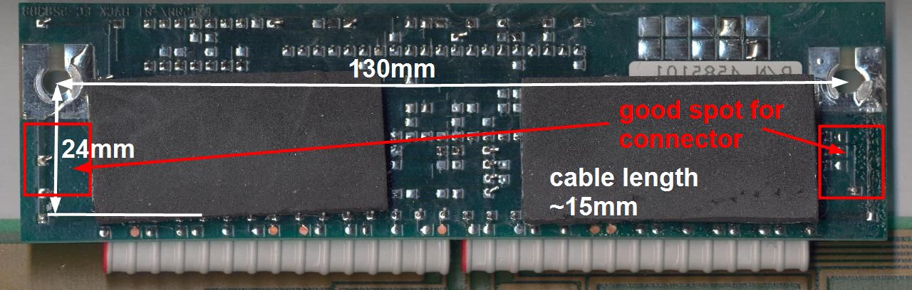
- controller.jpg (107.95 KiB) Viewed 10360 times
Posted: 02 May 2014, 00:10
by Muirium
Since I've not seen much made of the Kishsaver's little beeper daughterboard, I took some pictures for the details today. This is part of my cunning plan to get Xwhatsit to support it, like he does the beam spring solenoids!
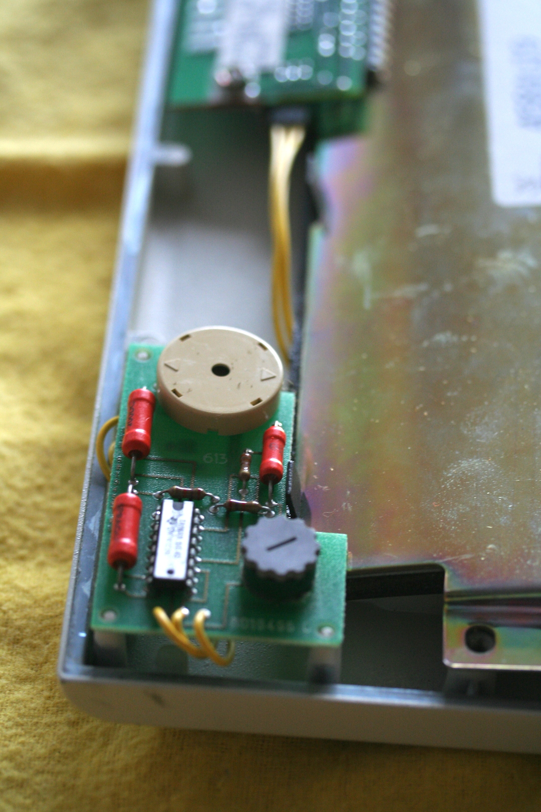
- Kishsaver Beeper Installed.JPG (760.42 KiB) Viewed 10282 times
The dial lines up with a hole on the underside of the Kish's metal case. For volume adjustment, I presume?
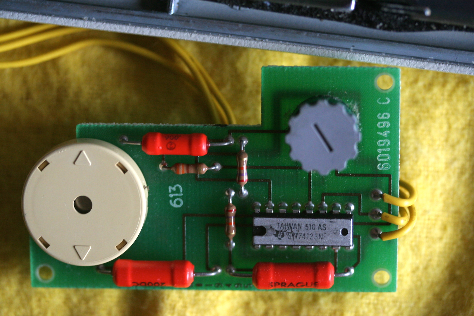
- Kishsaver Beeper Top.JPG (776.61 KiB) Viewed 10282 times
Naturally, I named these pictures confusingly. The beeper board's dial goes downward, when the keyboard is assembled. The PCB's "underside" is then pointing up.
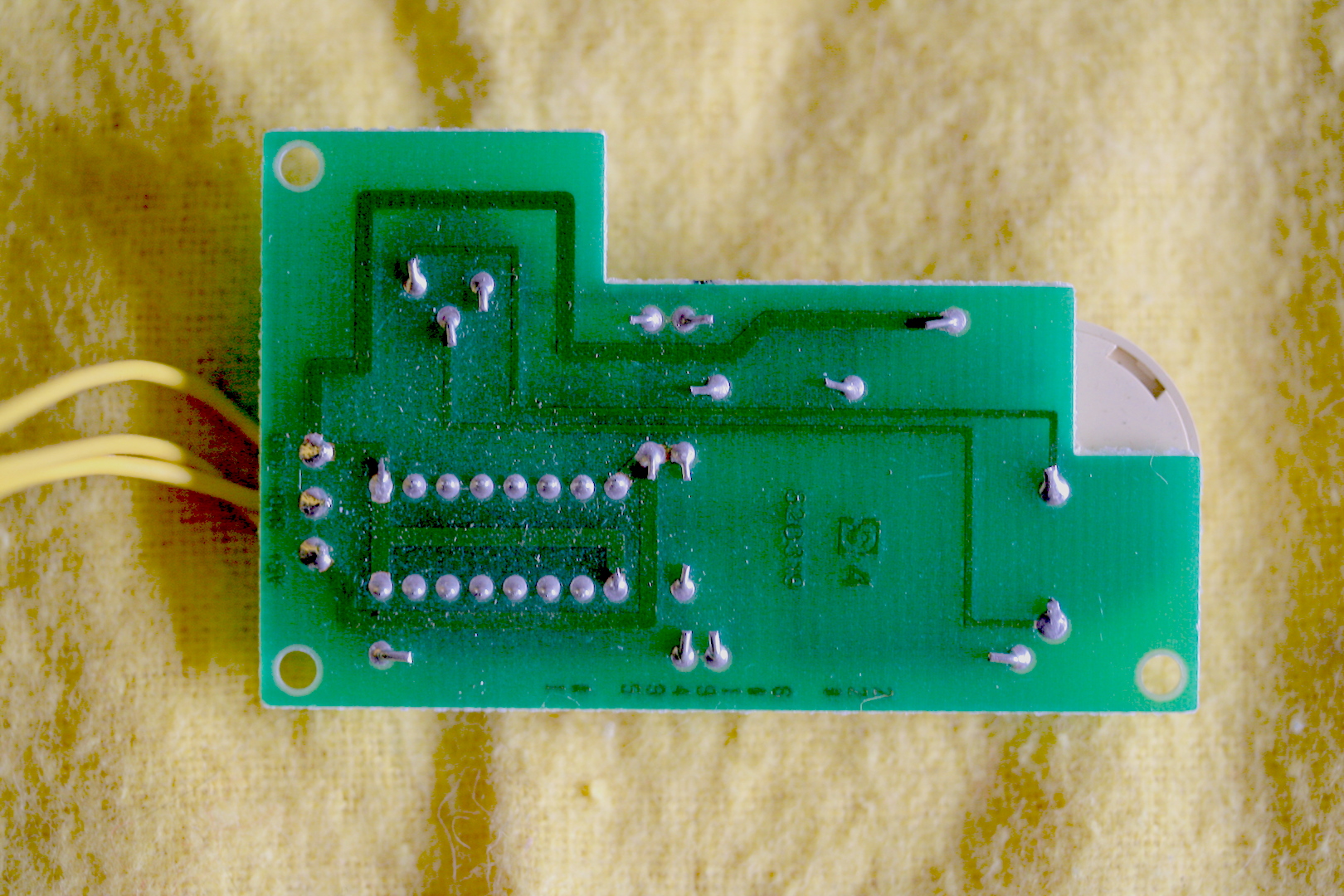
- Kishsaver Beeper Bottom.JPG (970.04 KiB) Viewed 10282 times
Pretty simply laid out. Here's a gratuitous macro.
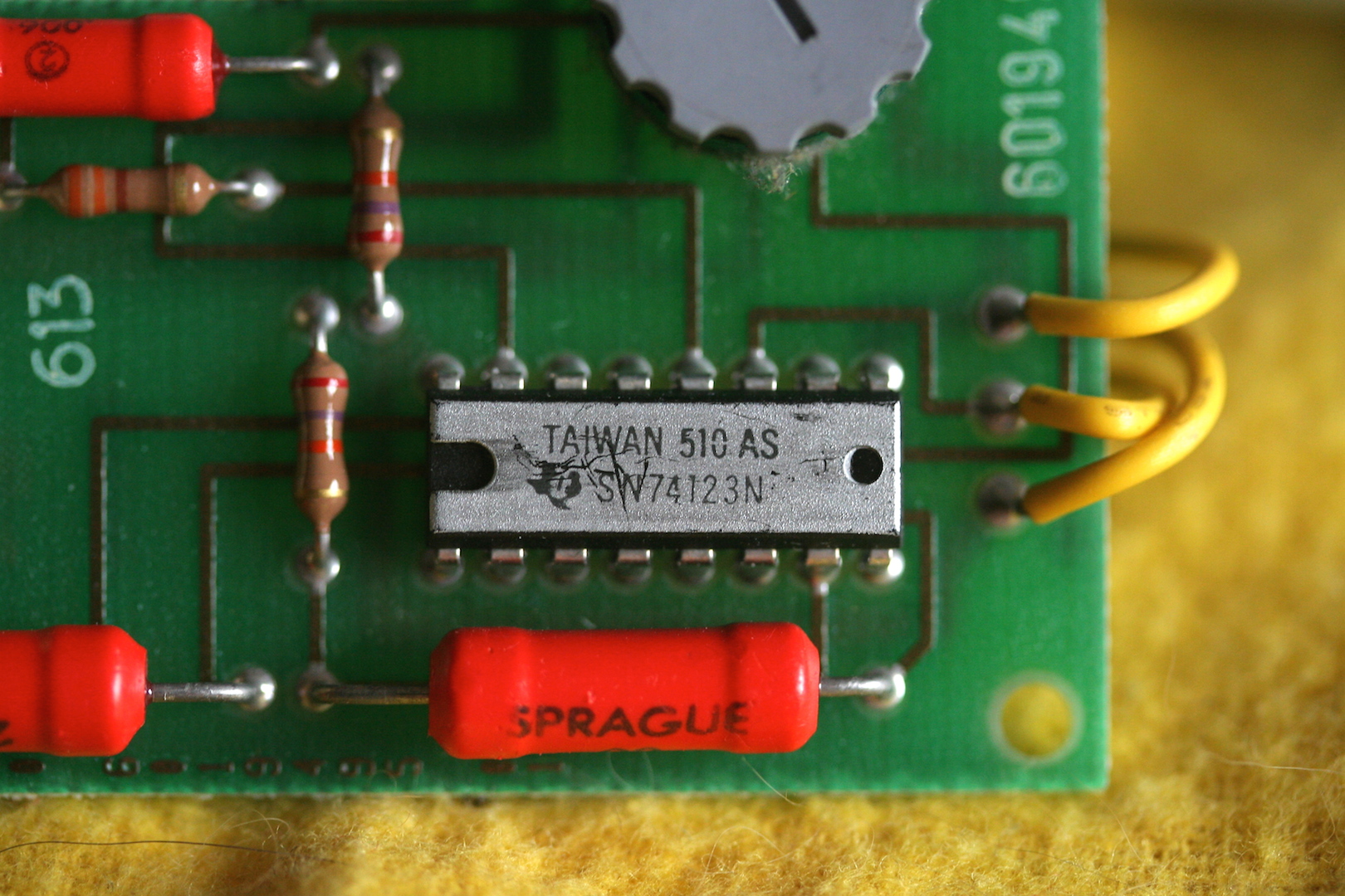
- Kishsaver Beeper Detail.JPG (809.42 KiB) Viewed 10282 times
And the important bit, for a replacement controller's perspective.
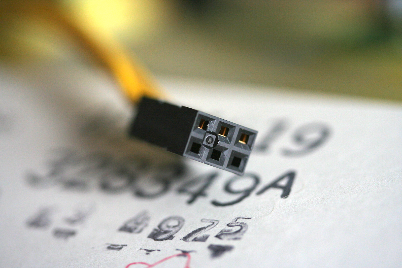
- Kishsaver Beeper Connector.JPG (847.19 KiB) Viewed 10282 times
Three populated pins. All yellow, but all easy to trace to the PCB.
For what it's worth, my Kishsaver is the late (1986) model. Here's the plate label.
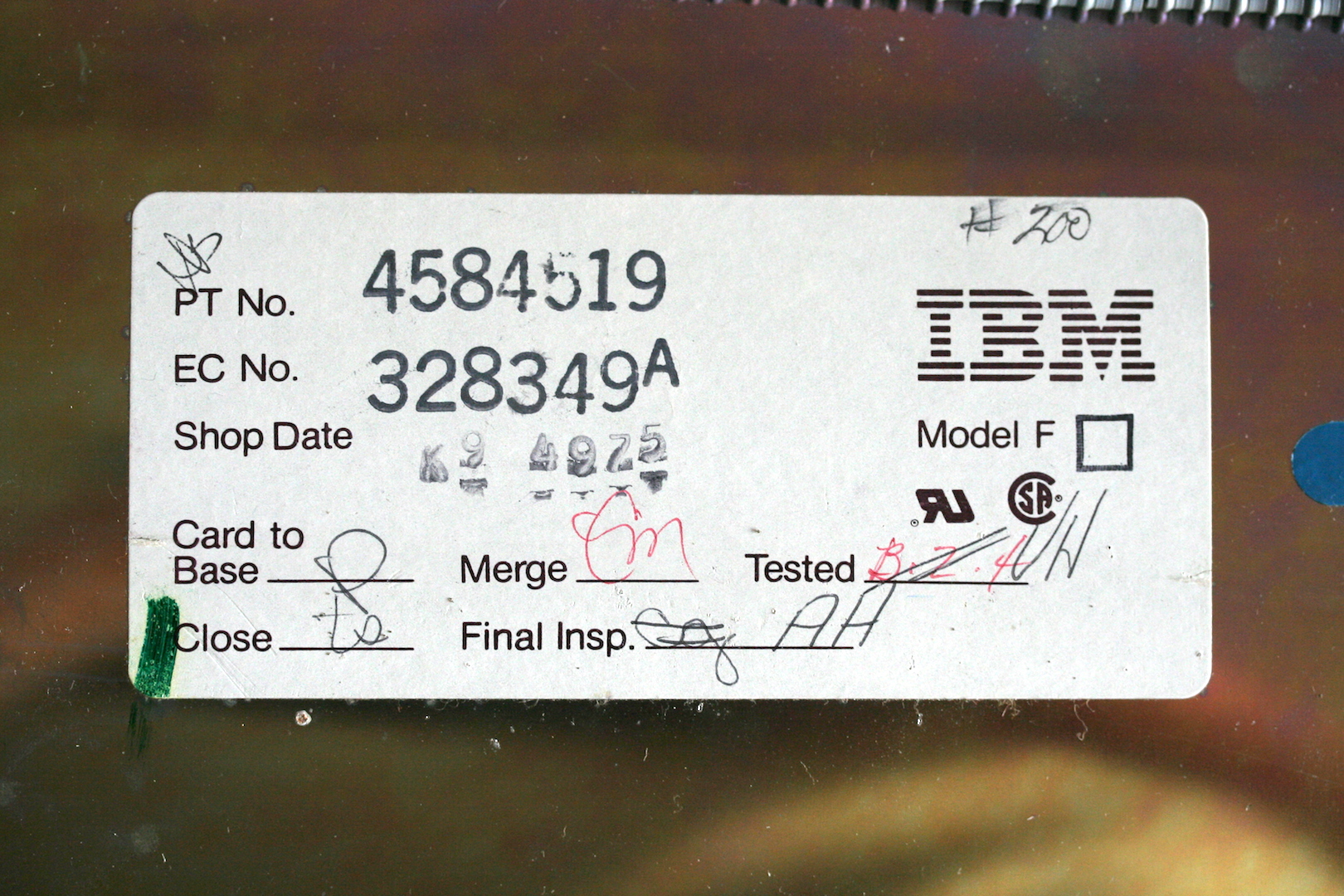
- Kishsaver Plate Label.JPG (1001.67 KiB) Viewed 10282 times
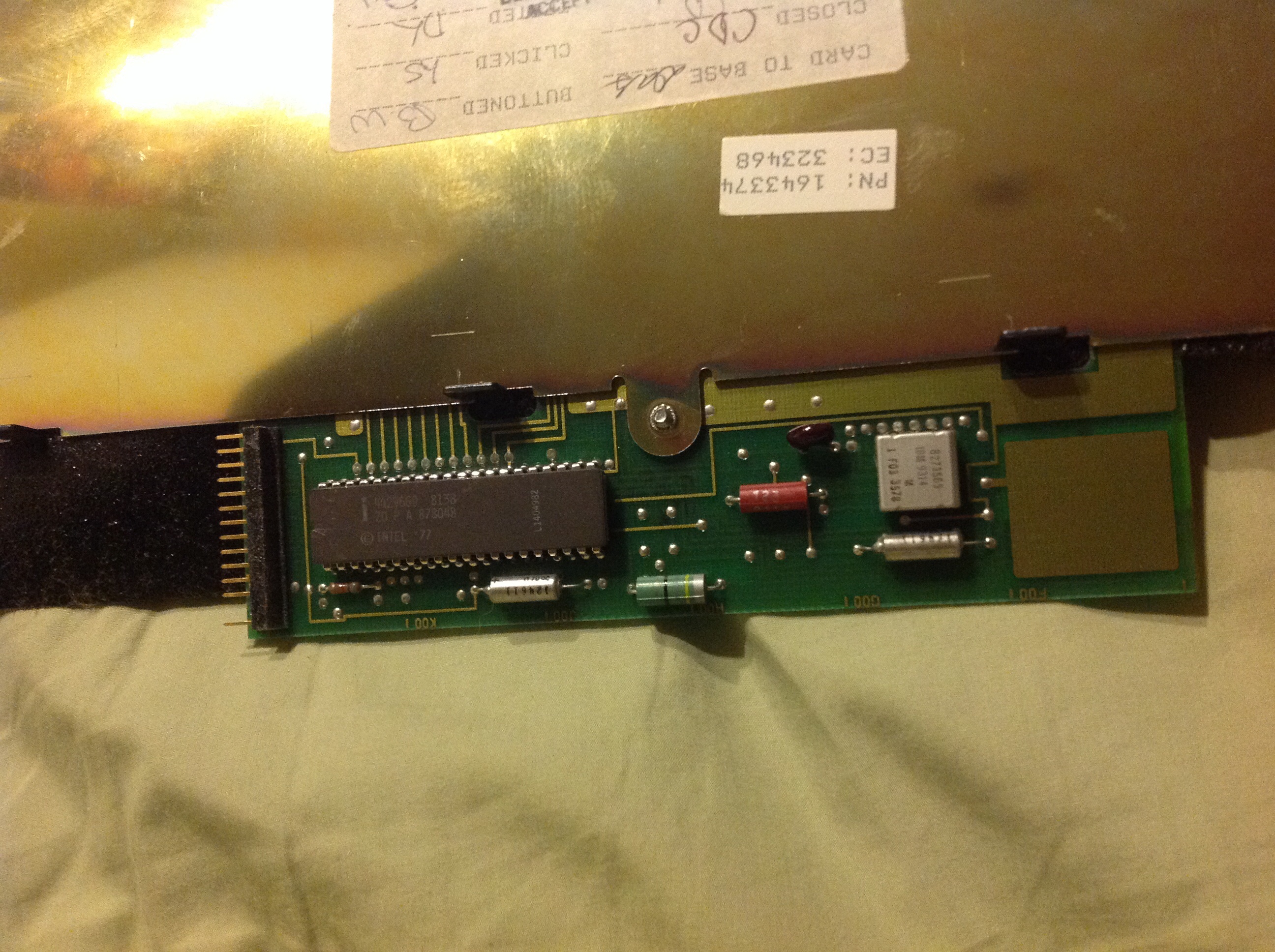
And the stock controller.
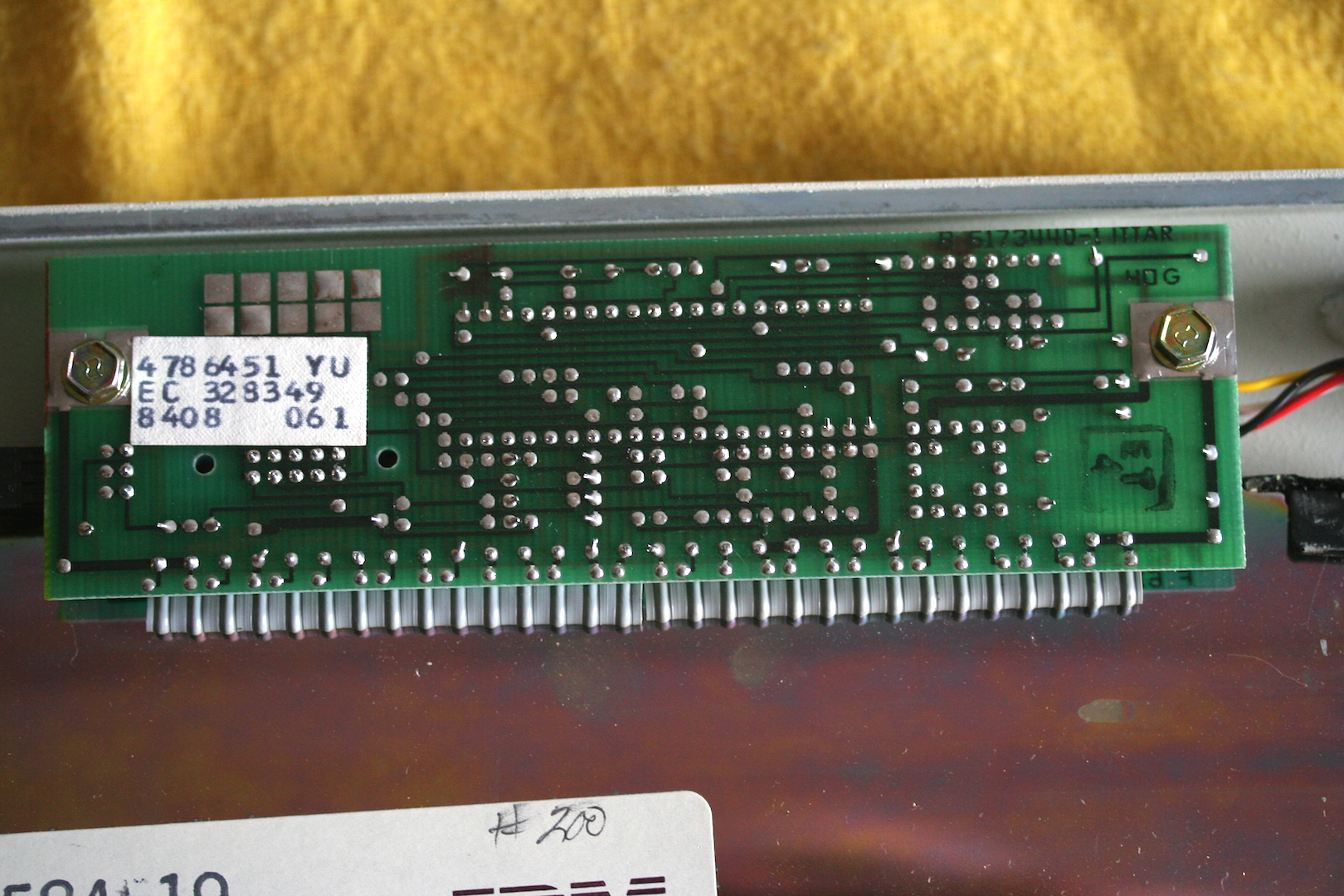
- Stock Kishsaver Controller.JPG (907.43 KiB) Viewed 10282 times
The daughterboard's three pins are on the far left. There's a fair old bit of slack in its cable, so I wouldn't worry about moving the socket.
Had it up and running today with Hasu's proof-of-concept converter.
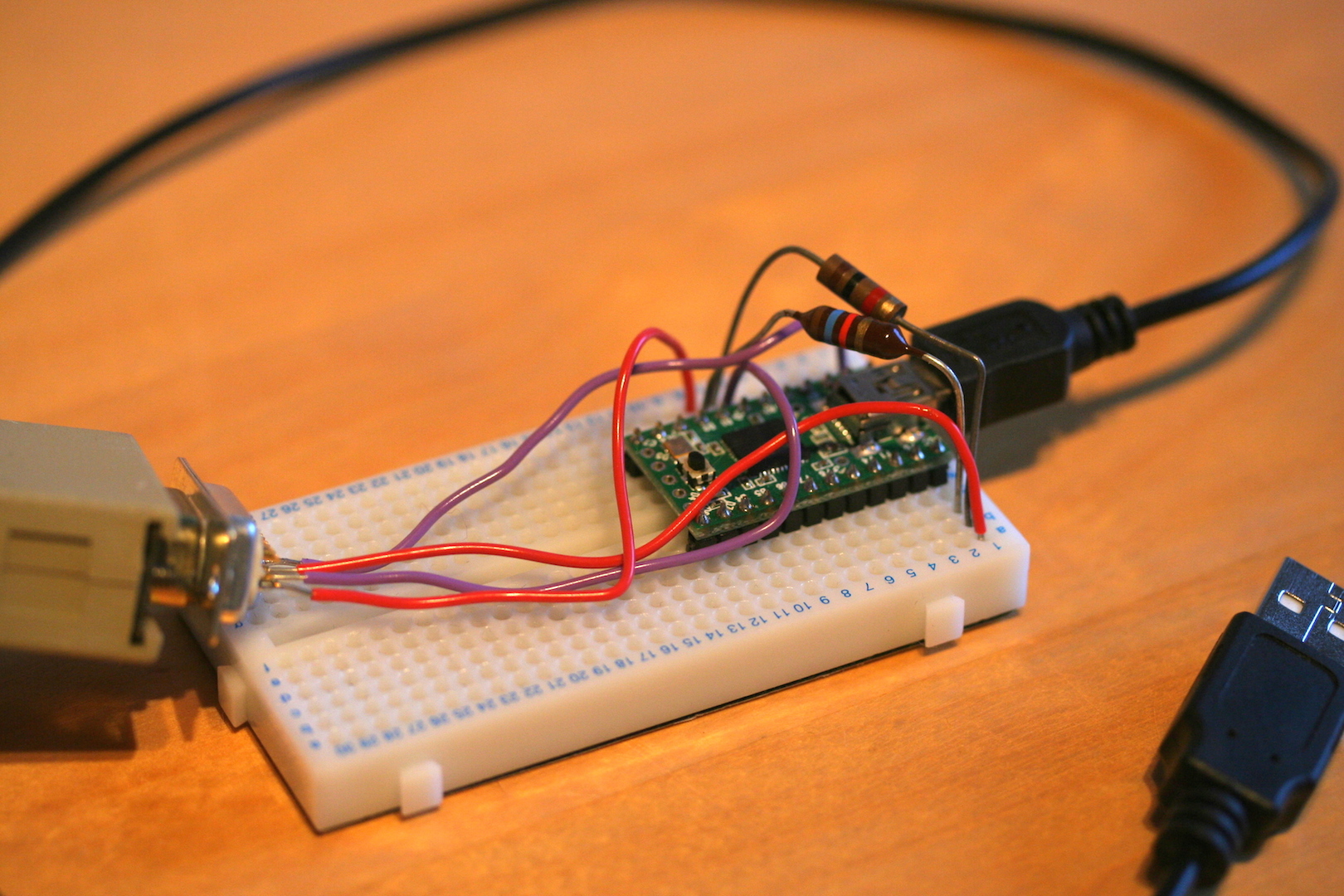
- Hasu's Kishsaver Converter.jpg (843.68 KiB) Viewed 10282 times
Which reminded me the apostrophe and S keys needed fixed. So I also did my first chopstick trick. Actually a clipped down matchstick in my case. The springs came out quite nicely, and I popped in a couple of Model M spares. Apostrophe works perfectly. But S proved to be a pain in the jacksie. The pads work, as it registers if you move the spring yourself, but with either Model F or M springs attached it only seems to pick up 1 in 10 keystrokes; despite making appropriate clicks. Ho hum. I may have to open up the plate sandwich yet.
Posted: 02 May 2014, 01:29
by xwhatsit
Ahh, lovely stuff Murium.
Looks like a piezo beeper I think, so I'm pretty sure it's only ever going to just beep annoyingly. The connector is a slight pain having all three pins on the bottom, as I have Vcc and GND at diagonal opposites. Might have to make a sort of adapter cable, or have the poor bastard wiring it up shift pins around in the connector.
Most likely that is a volume control; if the red things are capacitors (I can't tell) then it might be a sort of low-pass circuit. The 74123 is just a monostable, same as used in the beamsprings for the solenoid, to make it so you don't have to remember to turn off the `beep' signal in a particularly timely manner.
Can you identify which pin goes where? I think I can read `GND +OVR +5V' on the bottom of the board in the picture you posted. Which is which on the plug?
Excitingly the PCBs arrived today. Hopefully I can find some time to put them together and make the necessary software changes soon
