Difference between revisions of "Atari interface"
Findecanor (talk | contribs) (Added SAM Coupé) |
Findecanor (talk | contribs) m (→Commodore joysticks) |
||
| Line 390: | Line 390: | ||
===Commodore joysticks=== | ===Commodore joysticks=== | ||
| − | The [[Commodore VIC-20]] | + | The [[Commodore VIC-20]] has one "Control port". The [[Commodore 64]] and ''128'' have two. |
| − | + | All support Atari-standard joysticks and could technically also support the additional buttons on the "Booster Grip". | |
| − | The Commodore 64/128 | + | The Commodore 64/128 use the same I/O ports for joysticks as for the [[keyboard matrix]], but not having them part of it. Therefore, most single-player games support a joystick only in port 2, so that joystick and keyboard would not interfere with one-another. |
| − | Many games use the [[Space bar]] for additional input but strobing only for that key. Port 1's button is wired to the Space bar's column which means that pressing the button on a joystick in that port does in | + | Many games use the [[Space bar]] for additional input but strobing only for that key. Port 1's button is wired to the Space bar's column which means that pressing the button on a joystick in that port does in these games effectively press Space. Many two-button joystick mods for the C64 have taken advantage of this. |
| + | ==== Power Pad ==== | ||
The rare ''Commodore 64 Power Play'' Edition, sold only in Germany in 1990 came with a ''Power Pad''<ref>Retroport.de—[http://www.retroport.de/C64_Power_Play.html Commodore C64C Power Play Edition (1990)]. Retrieved 2018-06-07</ref> — a clone of a NES gamepad with two buttons. The two buttons worked the same in some games but different in others — it is unclear whether it worked like the Atari 7800 joystick or like a 2600 joystick + a booster grip button. | The rare ''Commodore 64 Power Play'' Edition, sold only in Germany in 1990 came with a ''Power Pad''<ref>Retroport.de—[http://www.retroport.de/C64_Power_Play.html Commodore C64C Power Play Edition (1990)]. Retrieved 2018-06-07</ref> — a clone of a NES gamepad with two buttons. The two buttons worked the same in some games but different in others — it is unclear whether it worked like the Atari 7800 joystick or like a 2600 joystick + a booster grip button. | ||
==== C64GS joystick ==== | ==== C64GS joystick ==== | ||
The doomed ''Commodore 64 Games System'' was essentially a [[Commodore 64]]C without a keyboard. | The doomed ''Commodore 64 Games System'' was essentially a [[Commodore 64]]C without a keyboard. | ||
| − | To compensate for the loss of keys, the joystick got a secondary fire function which shorted +5V to pin 9 (POTX), like the Thumb button on Atari's ''Booster Grip''. Note that on the Commodore Amiga, the same pin was read as secondary fire but low instead of high. | + | To compensate for the loss of keys, the joystick got a secondary fire function which shorted +5V to pin 9 (POTX), like the Thumb button on Atari's ''Booster Grip''. (Note that on the Commodore Amiga, the same pin was read as secondary fire but low instead of high.) |
The bundled ''Cheetah Annihilator'' joystick had a secondary fire button but unfortunately it broke easily and a replacement that supported secondary fire was practically nonexistent. | The bundled ''Cheetah Annihilator'' joystick had a secondary fire button but unfortunately it broke easily and a replacement that supported secondary fire was practically nonexistent. | ||
==== Amiga ==== | ==== Amiga ==== | ||
| − | + | Every [[Commodore Amiga|Amiga]] computers has two "Controller ports": port 1 labelled "Mouse" and port 2 labelled "Joystick" even though both have the same capabilities. | |
| − | + | ||
| + | The fire button and the mouse's left button use the same input, allowing either to work as the other when only button press is required. | ||
| + | Sega [[#Sega 8-bit|Master System]] and | ||
| + | [[#Sega_16-bit|Mega Drive/Genesis]] gamepads work on the Amiga, but only two buttons work: as Fire/Left Mouse and the Right mouse button. Some games, as well as some game controllers made for the Amiga support that second button, and some rare controllers even have a third button wired to the third mouse button's input. | ||
==== Amiga CD32 gamepad ==== | ==== Amiga CD32 gamepad ==== | ||
| − | The gamepad has | + | The gamepad has a [[D-pad]] and seven buttons: Blue, Red, Yellow, Green, Right Front, Left Front and Pause. |
| − | + | Games not specifically made for the CD32 would pull pin 5 low which makes | |
| − | + | Red work as Fire, and Blue as the second button. | |
| − | |||
When pin 5 is high, the button state is read serially on pin 9 from a 74LS165N shift register using pin 6 as a clock. The register is reset by setting pin 5 low again. | When pin 5 is high, the button state is read serially on pin 9 from a 74LS165N shift register using pin 6 as a clock. The register is reset by setting pin 5 low again. | ||
Revision as of 14:15, 10 November 2019
| This article requires additional photographic illustration |
Atari's video game console Atari 2600, released in 1977, introduced a input-device peripheral port that became the de-facto standard on 8-bit and later 16-bit home-computer as well as on some game-consoles up until the mid-1990s.
The port interface has been used primarily for digital joysticks/game controllers but also with different signalling for numeric keypads, trackballs and mice, paddles, analogue joysticks, light pens and various other types of controllers as well as non-input devices. Some alphanumeric keyboards were made but are very rare.
Contents
Connector
The connector is a 9-pin D-subminiature (DE-9[footnote 1]), male socket on the host and female plug on the device's cord.
Many hosts have the ports flush with the panel and quite close together, without any threaded nuts. Most device plugs are therefore narrower than standard DE-9 to be able to fit them. Many hosts ports have the "shield" made of non-conductive plastic.
Beware that not all input devices with a DE-9 connector actually use Atari-compatible pinout and/or signals. See Partially compatible and Incompatible below.
Pin-out
| Pin 1 | Pin 2 | Pin 3 | Pin 4 | Pin 5 | Pin 6 | Pin 7 | Pin 8 | Pin 9 | |
|---|---|---|---|---|---|---|---|---|---|
| Digital joysticks and gamepads | |||||||||
| Atari 2600 | Up | Down | Left | Right | Button | (+5V) | Ground | ||
| Booster grip | Trigger | +5V | Thumb | ||||||
| Atari 7800 | Up | Down | Left | Right | /Right button | 2600 button/Common | (+5V) | Ground | /Left button |
| C64 Power Pad C64GS |
Up | Down | Left | Right | Button | +5V | Ground | Button 2 | |
| Kempston Interface | Up | Down | Left | Right | (Button 3) | Button | (+5V) | Ground | (Button 2) |
| Amiga | Up | Down | Left | Right | (Button 3) | Button | (+5V) | Ground | (Button 2) |
| Amiga CD32 | Up | Down | Left | Right | Select | Red(Button)/Clock | +5V | Ground | Blue/Serial |
| SAM Coupé | Up | Down | Left | Right | 0v | Button | +5V | Common | Com 2 |
| Analogue controller | |||||||||
| Atari paddles | Left Button | Right Button | Right Pot | +5V | Ground | Left Pot | |||
| Commodore paddle | Left button | Right Button | Pot Y | +5V | Ground | Pot X | |||
| Amiga analogue joystick | (Button 3) | Button 1 | Button 2 | Pot X | +5V | Ground | Pot Y | ||
| Mice and trackballs | |||||||||
| Atari Trak-Ball | X direction / Up | X motion / Down | Y direction / Left | Y motion / Right | Button | +5V | Ground | ||
| Atari ST mouse | X1 | X0 | Y0 | Y1 | (Middle button) | Left button | +5V | Ground | Right button |
| Amiga mouse | Y0 | X0 | Y1 | X1 | (Middle button) or (Wheel/Middle button) | Left button | +5V | Ground | Right button |
| Amstrad/Sinclair PC mouse | X0 | X1 | Y0 | Y1 | (Spare) | Left button | +5V | Ground | Right button |
| Light pens and light guns | |||||||||
| Atari | Pressure/Trigger | Light sensor | +5V | Ground | |||||
| Magnum lightphaser | Trigger | Light sensor | +5V | Ground | |||||
| Stack light rifle | Trigger | Light sensor | +5V | Ground | |||||
| Gun stick | Hit | Trigger | +5V | Ground | |||||
| Amiga | Pressure/Trigger | Light sensor | +5V | Ground | |||||
| Keypads | |||||||||
| Atari Keyboard Controller, CX21 | Row 1 | Row 2 | Row 3 | Row 4 | Column 1 | Column 3 | (+5V) | Column 2 | |
| Atari CX85 | Bit 0 | Bit 1 | Bit 2 | Bit 3 | Bit 4 | Press | +5V | Ground | |
| Cardco, Rushware, Coplin | Bit 0 | Bit 1 | Bit 2 | Bit 3 | Press | +5V | Ground | ||
| ColecoVision | Up/Bit 0 | Down/Bit 2 | Left/Bit 3 | Right/Bit 1 | Keypad strobe | Left/Right button | (Spinner 1) | Joystick strobe | (Spinner 2) |
| Partially compatible | |||||||||
| Amstrad CPC | Up | Down | Left | Right | (Spare) | Button 2 | Button 1 | Common (row 9) | Com 2 (row 6) |
| J-PC | Up | Down | Left | Right | (+5V) | A | B | Out | Ground |
| Sega 8-bit | Up | Down | Left | Right | (+5V) | Button 1 | (Light sensor) | Ground | Button 2 |
| Sega 16-bit | Up | Down | GND/Left | GND/Right | +5V | A/B | Select | Ground | Start/C |
Most lines are active when shorted to a ground line (or strobe). Atari-compatible hosts should have a pull-up resistor on each such line. Input lines that can be active high are marked in bold. Outputs are marked in italics. Entries within parenthesis above are optional but supported by host hardware.
The state of the device's switches is often read directly over the wire. Video games were often running main loops synchronised to the video beam, so switches were polled at most 60 times per second — 16.7 ms interval, which is longer than what most switches are rated for contact bounce.
Hosts could not sense which type of device was connected to a port and software was most often hard-coded for a specific class of devices. In the cases where software could support different classes of devices, the user had to tell the software manually.
Digital joysticks and gamepads

Different systems have implemented the standard, sometimes with different extensions for more buttons or other capabilities.
The joysticks have eight directions and one button, often named "Fire" or "Trigger". The directions up, down, left and right have individual pins, with diagonals as combinations of up+left, up+right, down+left and down+right respectively.
Atari joysticks
Atari's joystick standard was introduced with the Atari VCS (Atari 2600 after 1982) and was then used on Atari 8-bit computers (400, 800, 1200, XL, XE) and the Atari ST line (including TT and Falcon). Most games consoles and home computers had two ports but the Atari 400 and 800 had four. Many third-party joysticks for this pinout do have more than one button, but only for convenience — they are all wired to the same line.
Joysticks with repeat-fire were supposed to use the +5V line for power but some were instead powered by the host's pull-up current on the button's pin.[1]
Atari released a Booster grip accessory for the 2600 with a passthrough for the joystick. It added a thumb button and a trigger; each on a POT line, shorting it to +5V when pressed and thus read as a paddle.
The Atari 7800 console has joysticks with two trigger buttons but the console is backwards-compatible, containing also Atari 2600 hardware. Each new trigger button is wired between the 2600's trigger pin and a POT line with pull-down resistors to ground. This setup means that the buttons are two different buttons in 7800 mode but have the same function in Atari 2600 mode. [2]
Commodore joysticks
The Commodore VIC-20 has one "Control port". The Commodore 64 and 128 have two. All support Atari-standard joysticks and could technically also support the additional buttons on the "Booster Grip".
The Commodore 64/128 use the same I/O ports for joysticks as for the keyboard matrix, but not having them part of it. Therefore, most single-player games support a joystick only in port 2, so that joystick and keyboard would not interfere with one-another. Many games use the Space bar for additional input but strobing only for that key. Port 1's button is wired to the Space bar's column which means that pressing the button on a joystick in that port does in these games effectively press Space. Many two-button joystick mods for the C64 have taken advantage of this.
Power Pad
The rare Commodore 64 Power Play Edition, sold only in Germany in 1990 came with a Power Pad[3] — a clone of a NES gamepad with two buttons. The two buttons worked the same in some games but different in others — it is unclear whether it worked like the Atari 7800 joystick or like a 2600 joystick + a booster grip button.
C64GS joystick
The doomed Commodore 64 Games System was essentially a Commodore 64C without a keyboard. To compensate for the loss of keys, the joystick got a secondary fire function which shorted +5V to pin 9 (POTX), like the Thumb button on Atari's Booster Grip. (Note that on the Commodore Amiga, the same pin was read as secondary fire but low instead of high.)
The bundled Cheetah Annihilator joystick had a secondary fire button but unfortunately it broke easily and a replacement that supported secondary fire was practically nonexistent.
Amiga
Every Amiga computers has two "Controller ports": port 1 labelled "Mouse" and port 2 labelled "Joystick" even though both have the same capabilities.
The fire button and the mouse's left button use the same input, allowing either to work as the other when only button press is required. Sega Master System and Mega Drive/Genesis gamepads work on the Amiga, but only two buttons work: as Fire/Left Mouse and the Right mouse button. Some games, as well as some game controllers made for the Amiga support that second button, and some rare controllers even have a third button wired to the third mouse button's input.
Amiga CD32 gamepad
The gamepad has a D-pad and seven buttons: Blue, Red, Yellow, Green, Right Front, Left Front and Pause. Games not specifically made for the CD32 would pull pin 5 low which makes Red work as Fire, and Blue as the second button.
When pin 5 is high, the button state is read serially on pin 9 from a 74LS165N shift register using pin 6 as a clock. The register is reset by setting pin 5 low again. [4]
ZX Spectrum
The original Sinclair ZX Spectrum did not originally come with a joystick port so most games used the keyboard. The standard was to use 5-8 on the numeric row as cursor keys.
A two-port expansion card called ZX Interface 2 was released by Sinclair but not before the single-port Kempston Joystick Interface expansion card from Kempston Micro Electronics had established itself on the market. The ZX Interface 2 mapped joysticks to keyboard keys on the numeric row — but to different keys than the cursor standard. Other cards exist that map to either, to both or to both and the older keyboard standard.
The ZX Interface 2 does not connect the +5V line, so joysticks with turbo/auto-fire do not work. [5] The Kempston does not only connect the +5V line, it also allows lines 9 and 5 to be read as buttons.[6]
The Spectrum +2 and later (the Amstrad era) did come with 2 DE-9 joystick ports that were used like the ZX Interface 2's ports by programs — but the pinout is different from the Atari standard.
SAM Coupé
The SAM Coupé 8-bit computer has a single joystick port that connects one Atari-compatible joystick, or two with an adaptor.
Both inputs and the strobe lines are shared with the keyboard matrix, with each joystick's inputs producing keycodes that already exist on the keyboard. Each common line on the connector strobes each joystick in turn. An adaptor would need diodes to avoid joysticks from clashing. Because the hardware is "temperamental", it is recommended to use germanium diodes with a low voltage drop, or to use a tristate buffer for each joystick. [7].
Paddles
A paddle is a controller with a turnable knob. The name comes from what they were initially used for: for moving a paddle on the screen back and forth in the game Pong which simulated table tennis. Paddle controllers were typically two on a Y-cable to the same port.
Each paddle's knob is on a rotary potentiometer, connected to +5V in one end and with the wiper connected to the pot line and only a capacitor against ground for smoothing the signal. Turning the knob right decreases the resistance. Note that ground is not connected: The potentiometer does not alter the voltage but the current on the pin. Paddles are read relatively slowly by charging a capacitor and measuring the discharge time. Analog-to-digital converters don't work.
Paddles for the Commodore machines have the Atari pinout but the potentiometers are 470 kohm instead of 1 Mohm. This means that Atari paddles are usable on Commodore machines (only with less range) but not the other way around.[8] The paddle interface was used also for mice for the Commodore 64 and for analogue joysticks for the Commodore 64 and the Amiga.[9]
Keyboards
Atari 7800 keyboard
A QWERTY keyboard had been announced for the Atari 7800 video games console when it was launched in 1984 but the keyboard was never released. The keyboard was the same as in the 600/800XL but with a special controller, and connected via port 2.[10].
Keypads
Atari 2600 Keyboard Controller
Several pins on the Atari 2600 and 8-bit computers were bidirectional and could be put to other use. The Keyboard Controller has a telephone-style numeric layout with # and * buttons, exposed as a 4×3 matrix using the direction, Trigger and Pot lines.[11] It was often used with Atari 8-bit computers as a numeric keypad.
Atari CX85 Numerical Keypad
The Atari CX85 Numerical Keypad had 17 keys and a different protocol from the previous keyboard controller. Instead of exposing a matrix, it produces a scancode on the direction and pot lines. [12]
Cardco Cardkey
The Cardkey is a 16-key keyboard that produces a scancode + "button" press. The C64 driver also supports the CX85. The scancodes for the numeric keys are the values printed on those keys. Each key is set up only with diodes to the input lines which means that there is only 1-key rollover and two keys at once would produce the wrong scancode.[13]
Rushware keypad
Produces the same scancodes as Cardco Cardkey but activates differently.[14]
Coplin keypad
Nicholas Coplin has designed and published free schematics for a numeric keypad as well as a driver for the Commodore 64. Keys produce the same codes as corresponding joystick directions, allowing the keypad to be used as cursor keys in programs that were made for joysticks. This includes also diagonals, so e.g. key 8 + key 4 = key 7. Keys 0 and 5 produce opposing directions at once and Enter is wired to Fire. [15]
ColecoVision controllers
The ColecoVision games console and Coleco Adam computer supported Atari joysticks (without autofire) but came with extended controllers that had not only a joystick but two buttons and a 3×4 numeric keypad all in one. Instead of one ground line they had two strobe lines: the pin 8 for the Joystick in Atari-compatible fashion, and pin 5 activating the second button and keypad providing a scancode instead of a direction.
The Super Action Controller has also two additional buttons wired as part of the keypad and a horizontal wheel ("Spinner") producing a quadrature code.[16]
Mice and trackballs
Typical ball-mice and trackballs with opto-mechanical sensors for the X and Y axes, have each producing two pulse trains that are 90 degrees out of phase with one-another. (The same as a 2-bit Gray code, also called "quadrature encoding")
8-bit machines
It was problematic for an 8-bit machine with no dedicated hardware to read quadrature code fast enough and still have time for other processing.
Atari's Trak-Ball controllers for the Atari 2600 converted the quadrature code into either joystick input or into direction and motion pulses.[17] The latter signalling meant that a missed reading would only cause failing to move one (or more) steps instead of moving in the wrong direction. Mice and trackballs for Atari's 8-bit home computers used the same type of signalling.
Commodore's own mice either emulated a joystick or used potentiometers (like paddles) that wrapped around.
Mice for J-PC machines have instead internal logic for reading the encoders, with the obvious drawback that they were more expensive. The mouse presents X and Y byte-counters as nybbles on pins 1-4 in alternating order, but the other pins follow the J-PC pinout which does not work with the Atari-standard without an adaptor. The NEOS Mouse for the Commodore 64 was in essence a J-PC mouse, with the pinout changed to work with the Commodore 64. [18]
Atari ST and Amiga
Mice for both the Amiga and Atari ST provide pulse trains and buttons directly without any interpretation. (Thus, they are technically bus mice) Some third-party mice have support for both systems, selected via a switch that only changes which pins the quadrature signals go to. The left mouse button is wired the same as a joystick's Fire button and the other button(s)s also short to ground.
On the Amiga, signals are interpreted by circuitry in its custom chipset and there is hardware support for a mouse in each port. A second Amiga mouse can be used only in some two-player games, however. On the Atari, the mouse (and joysticks) are plugged into the keyboard and interpreted by the keyboard's microcontroller. A curious detail is that the Atari ST's right mouse-button is wired to and read as the other port's Fire button.
Amigas typically have two-button mice. Commodore made a three-button mouse only for the Amiga 3000UX that ran Amiga UNIX but many third-party Amiga mice also came with middle-button. In the late 1990s, there appeared third-party Amiga mice with scroll wheels, using varying current on the POTX line (pin 5) for input which required a special driver. The third button is represented in a new way.[19]
The Amiga's operating system provides (when booted into Workbench) also mouse keys as combinations together with the Amiga keys.
PC bus mouse
When Atari and Commodore started offering IBM-compatible PCs with built-in mouse support, they reused their mice and ports from the Atari ST and Amiga respectively as bus mice. Atari's "STM1" mouse got relabelled as "PCM1" for use with Atari PCs.[20]. The Atari PC's mouse ports support a third (middle) mouse button [21], whereas the Atari ST does not. Amiga-compatible mouse ports were standard (on the motherboard) on the Commodore PC10-III and PC20-III.[22]
Amstrad PC-1512[23], PC-1640[24] and Sinclair PC-200[25] (made by Amstrad) got a dedicated 9-pin port for a bus mouse. They use almost the Atari ST pinout except that the horizontal axis is flipped. A curious detail is that the two mouse buttons' lines were fed to the keyboard and reported by it as key codes.
Steering wheels
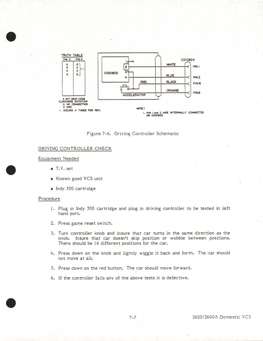
The Driving Controller accessory for the Atari 2600 looks similar to Atari paddles but the knob can be turned around without any stops. It uses a 16-stop rotary encoder but produces pulse trains on pins 1 and 2. [26]
Steering wheel controllers for the Amiga were supposed to also use the same pulse-train signalling as mice.
Light pens and light guns
Atari 2600, 7800 and 8-bit computers and Commodore's C64 and Amiga supported light pens and light guns through a line in one port connected to the video chip.
A light pen had a pressure-switch at the tip to tell the host when to read the screen position where as a light gun used a finger-operated trigger for the same purpose. The light sensor shared the same pin as a joystick's button, so the pressure had to use a different pin and that differed a bit between devices.
Light pens and light guns for the Atari 8-bit computers grounded pin 1 (up) [27] For the Commodore 64, most light pens also used pin 1 [28] but the most popular light guns shorted pin 5 (POTY) to +5V.[29] Stack's light rifle grounded pin 3 (left)[30]. Devices for the Amiga were supposed to use pin 5[9].
Sega lightphasers had a different pinout but could be used with an adaptor or mod.[31]
The Gun stick light gun for the C64 instead worked like the light gun on the Nintendo Entertainment System: when the trigger was pressed, the screen would turn black except for a white field for one valid target at a time.[32]
Partially compatible
Input devices with DE-9 plugs that may work with some Atari-compliant hosts but are unsafe to use with others, or vice versa.
Amstrad
The Amstrad CPC computers has one or two "User ports" for two-button Amstrad joysticks. Amstrad PC-1512[23] and PC-1640[24] had a single Amstrad "Joystick" port on the keyboard. The joystick port/s are actually part of the computer's keyboard matrix and are strobed by the keyboard controller.
Many games used Button 2 as primary fire, so they supported Atari-standard one-button joysticks. If Button 1 was needed, its function was often also on a keyboard key. The opposite however: using an Amstrad joystick in a Atari-compliant port (such as the Amstrad/Sinclair PC mouse port) could damage the system because pressing Button 1 would short the +5V line to Ground.
The CPC supported up to two joysticks on the same port, using pass-through or adaptor, using diodes to avoid ghosting. The first joystick had its ground line strobed on pin 8, and the second on pin 9 — each being a separate column in the keyboard matrix.
CPC+/GX4000 had two ports through wiring almost like such an adaptor except that diodes were missing for the fire buttons, thus introducing conflicts between joysticks. The two-port machines also lacked the "spare" line and were incompatible with some older peripherals, especially those that had been using pins as outputs. [33]
Amstrad PC's did not support a second joystick, and Sinclair PC-200 had an IBM-compatible Game port instead[25].
J-PC
The J-PC standard was used by primarily Japanese systems such as MSX (multiple manufacturers), FM Towns and the Sharp X68000 and on expansion cards for Japanese PC systems.
The "Out" strobe on pin 8 is used by the host to access special features on certain controllers, such as MSX-compatible mice. Most games will keep pin 8 grounded, which will allow Atari-compatible joysticks to be used.
The gamepad for the FM Towns Marty had also Run and Select buttons, implemented as Left and Right, and Up and Down respectively.[34]
Mice and trackballs for J-PC machines had logic in them instead of requiring logic in the host, and therefore a different interface. An Amiga or Atari-compatible mouse must never be connected to a J-PC system, as pressing the right mouse button would short +5V to Ground.
See also:
- SpectraVideo SV328 — a MSX computer with two J-PC ports.
Sega
Sega 8-bit
Sega's various 8-bit consoles had mostly the same hardware, albeit upgraded in later models and with small differences between Japan and the outside world. The first SG-1000 came with two joysticks. The SG-1000 Mark-II and SG-1000 Mark-III had gamepads, each with a detachable joystick nub on the d-pad. The Sega Master System came with gamepads without joystick nubs.
The standard controllers are passive devices containing switches and no electronics, so they should be safe to use with Atari-compliant host sockets.[Citation needed]
Paddles for the SG-1000 Mark III/Master System contain an A/D converter and presents the reading in 8 bits divided into nybbles on lines 1-4, with pin 9 to indicate high/low nybble. On the Master System outside Japan, the pinout was slightly different so the host first selected high/low nybble on pin 7.[35]
Sega 16-bit
The three-button controller for the Sega Mega Drive/Genesis uses a 74157 selector to allow four buttons and a four-directional D-pad. The Select pin selects between two sets of inputs. Select=Low:A/Start, Select=High:Left/Right/B/C. The normal state for the Sega host is to have the select pin high, and to pulse it low for a short time during each video frame period when it polls the inputs. [36]
The signalling is close enough to the Atari standard that a Sega 16-bit controller could be used with some standard-compliant hosts. The Sega controller expects +5V on pin 5, and setting pin 7 high (Atari +5V) sets the selector in a mode that makes the D-pad work as expected and the B-button work as Fire.[37] The gamepads were popular on the Amiga where the second button was supported by many games. However, unlike the Atari standard which has pull-up resistors on each input line on the host side, Sega 16-bit systems have them in the controller. This means that lines are high when not active, and this current could damage some hardware. For instance, the Commodore 64 and 128 computers reused the same physical lines for ports and the keyboard matrix, which could lead to excess current into the I/O chip (CIA #1) if a key is pressed while a Sega gamepad is plugged in. The host could however be protected with a simple adaptor with diodes on the input pins. [38]
Sega's six-button controller for the Mega Drive/Genesis has a microcontroller instead of a selector chip. The host pulses the Select line low at least four times per video frame in quick intervals. During the third pulse, lines 1 through 4 all read low and during the fourth pulse, lines 1 through 4 all read high, but in-between those two pulses they read the values of Z, Y, X and the mode switch respectively. Within that special period, pins 6 and 9 always read high. For six-button reporting to kick in, the pulses must be short enough with a long enough interval until the next time. There is also a mode-switch for disabling six-button behaviour in the controller for older games that used different timing for the select-line. [39] [36]
Other Sega 16-bit peripherals that used the DE-9 ports included a keyboard, keypad, mice, light guns and multiplayer adaptors. A keyboard accessory was made for the Sega Genesis/Mega Drive to be used with Internet multiplayer services from XBAND (US) and Teclado Mega Net (Brazil). It was connected to port #2.[40]. The ports did not have any serial hardware, so the protocol was probably "bit-banged" by the CPU.
Related
Other ports than DE-9 with compatible signals.
Parallel port
The DB-25 parallel port was a de facto standard for many years, standardized as the IEEE 1284 first in the late 1990s when it was being phased out in favour of USB.
It was found on Amiga, Atari ST, most Unix workstations and on IBM PCs and compatibles for many years, most often used for connecting to a Centronics-port on a printer in the other end. Even though it had many uses, it was therefore often called a printer port. Apple Macintosh however, never had it because it used a proprietary serial interface to printers.
Numerous adaptors have been made from digital joysticks and gamepads to DB-25 parallel ports. For instance, a Multi Joystick Extender allowed two additional joysticks to be connected to an Amiga or Atari ST. This did require specific software support and not many games supported them.[41]
Commodore 116 joystick
The unusual Commodore 116 line, including the Plus 4 and Commodore 16 had two mini-DIN ports instead of the standard DE-9 ports. Those were electrically compatible to the Atari standard and joysticks could be used with a simple adaptor. It has though been reported that the interface chip inside those computers could be damaged by joysticks with auto-fire capability. [42]
Atari Extended Joystick Ports

The Atari STe and Falcon computers have also two DE-15 Extended Joystick Ports. Each of these ports could with a Y-cable connect two DE-9 joysticks.[43]
Atari Jaguar
The Atari Jaguar's game controllers also have DE-15 connectors but with its own pin-out exposing a button matrix. These could be used with 15-pin ports on the STe and Falcon albeit with a different pinout than intended for these ports. The Jaguar controller's directions and one button are on the same matrix column which allows adaptors to DE-9 ports to be constructed with simple wiring. [44]
Incompatible
Different pinout
DE-9 connectors with different pinout, but are signal-compatible with a passive adaptor (may or may not require diodes).
Spectrum +2
Sinclair Spectrum +2 and later (Amstrad era) have two joystick ports. They are accessed by programs in the same manner as the ZX Interface 2 but the pinout is no longer Atari-compatible but specific to this line of computers.
TI-99
The Texas Instruments TI-99/4A has a different pinout on its DE-9 port. It supports supports two digital joysticks by strobing different ground lines (like Amstrad CPC). An adaptor should have diodes to avoid interference.[45]
Vectrex
A Vectrex controller has an analogue joystick and four buttons. Each of the analogue stick's potentiometers have its ends connected to -5V and +5V and uses different resistor values than Atari, plus a slightly different pinout. [46] Nonetheless, adaptors both to the Atari standard[47] and from digital Atari and Sega controllers have been made.
Different signalling
Incompatible, that would require an active converter to connect:
- Serial mice for the IBM PC, with RS-232 signalling.
- Some Intellivision consoles have a DE-9 plugs for each of its controllers. The joystick has 16 directions, there are three buttons and a keypad — each producing a scancode shorted to ground (pin 5). Buttons and directions don't interfere though. An adaptor from an Atari joystick would require some logic and perhaps external power.[48]. The Intellivision Flashback console also has DE-9 connectors but the pinout is different.[Citation needed]
- Gamepads for the 3DO console. They used serial communication for up to eight controllers daisy-chained from the same host port. Each also had a headphone jack with stereo sound.[49][50]
- Several clones of the Nintendo Famicom — "Famiclones" used DE-9 ports with Nintendo's serial protocol.
Different gender
Other uses of 9-pin d-subminiature but different signals and different gender from the Atari standard:
- Analogue joysticks and paddles for the Apple IIGS.
- SGI mouse 021-0004-002 used a serial protocol.[51][52]
Adaptors to USB
Active adaptors (protocol converters) have also been part of keyboard-adaptors for e.g. the Commodore Amiga and Commodore 64.
Open source/hardware
- Stelladaptor. Designed especially for the Atari 2600 emulator Stella. Once manufactured by AtariAge, then discontinued and opened up. Handles joystick as analogue USB joystick. Input from paddles and driving controller are in a special format that Stella treats differently if from a "Stelladaptor". Based on the PIC16C745.
- Simon Inns' Atari joystick USB adapter. Schematics and source code for two-port joystick-only adaptor. PIC18F2550 µcontroller available under the Creative Commons license.
- MatthewH's Classic Joystick to USB Keyboard Adaptor. Arduino "sketch" for the Arduino Leonardo.
- Kair.us Jakadapter. Supports two joysticks, paddles and Sega gamepads. Based on the PIC18F24K50.
For sale and Open Source
- Retronic Design Universal DB9 to USB joystick adapter module. Using the ATMEL ATMEGA 328p. Different firmware for different classes of peripherals.
- Raphnet Atari/SMS/Genesis joystick/controller/multi-tap to USB adapter Primarily for Sega Mega Drive/Genesis, but supports also Atari-compatible joysticks.
Commercial
- 2600-daptor. Four generations with different capabilities. Latest supports a large number of devices, with DIP switches or auto-detect if holding down first button when connecting.
- Retro-Bit Atari 2600 to USB adapter. Connects two joysticks.
- RetroUSB USB Atari RetroPort. Joysticks only.
Footnotes
- ↑ The DE-9 is very often incorrectly labelled as DB-9 or DB9, even within the electronics industry. The letter after 'D' actually signifies the size of the connector. An actual DB-9 port would be as wide as a DB-25 serial port but have only nine pins. The DE-9 shares size with DE-15 (known for VGA)
External links
- DB9-Joystick on Individual Computers' Product information Wiki.
- Atari joystick port on Wikipedia.
- The Industry Standard Atari-Style Joystick on the Nerdly Pleasures blog.
- Control Port on the C64 Wiki.
- SegaRetro.org — A wiki on the Sega consoles and their peripherals, several of which used semi-compatible interfaces.
References
- ↑ Jakadapter. Section "Hardware", third paragraph. Dated 2018-10-20. Retrieved 2018-12-02
- ↑ AtariAge 7800 FAQ. Retrieved 2017-03-30.
- ↑ Retroport.de—Commodore C64C Power Play Edition (1990). Retrieved 2018-06-07
- ↑ CD32 Gamepad A100 re-engineered documentation. Retrieved 2015-08-16.
- ↑ Sinclair ZX Resource Centre — ZX Interface 2. Retrieved 2018-05-24
- ↑ 8bit Projects for Everyone—Kempston Joystick. Dated 2002-10-12. Retrieved 2018-05-24
- ↑ WorldOfSam.org—Keyboard and Joystick port. Dated 2018-05-16. Retrieved 2019-10-05
- ↑ Projects of Jan Derogee — C64 Paddles. Retrieved 2018-05-23
- ↑ 9.0 9.1 AmigaOS 3.5 Developer Docs — Amiga Hardware Reference Manual: Interface hardware: Controller Port Interface. Retrieved 2018-04-18.
- ↑ Atari Museum—The Atari 7800 PRO System Computer Keyboard. Retrieved 2018-11-16
- ↑ Atari 400/800 Hardware Manual, Dated 1982. Retrieved from [www.atarimania.com AtariMania] on 2018-04-24
- ↑ Atari CX85 Numerical Keypad Technical References Notes. Retrieved from [www.atarimania.com AtariMania]
- ↑ Post by buzbard in the lemon64.com forum—Numerical keypad from Commmodore calculator? on 2012-09-12. Retrived 2018-06-11
- ↑ C64 Wiki—Rushware keypad. Last edited 2016-12-05. Retrieved 2018-06-12
- ↑ 64HDD—Numeric Keypad by Nicholas Coplin.
- ↑ Programming Ponderings—Ultimate Classic Game Console Joystick to USB Adapter. Dated 2015-12-28. Retrieved 2018-04-24
- ↑ AtariMania — Atari CX22 Trakball Field Service Manual. Rev 01. Nov 1983. Retrieved 2018-06-05.
- ↑ C64 Wiki—NEOS Mouse. Dated 2017-05-09. Retrieved 2018-06-07
- ↑ Micromys.de—Micromys support page - Amiga mouse mode with wheel support. Dated 2000. Retrieved 2019-03-24
- ↑ AtariPC.net—PC3 8088. Retrieved 2019-03-24
- ↑ Atari PC Owner's manual Scan on ataripc.net. Page 65. Dated 1987. Retrieved 2019-03-24
- ↑ Ancient Electronics blog—[https://ancientelectronics.wordpress.com/2015/06/17/commodore-colt-commodore-pc10-iii-pc20-iii/ Commodore Colt (Commodore PC10-III, PC20-III)
- ↑ 23.0 23.1 Amstrad PC1512 Technical Reference Manual. Copy on John Elliott's homepage, retrieved 2019-03-29
- ↑ 24.0 24.1 AMSTRAD PC1640 TECHNICAL MANUAL. Copy on John Elliott's homepage, retrieved 2019-03-29
- ↑ 25.0 25.1 The Vintage Computer Club Malta—SINCLAIR PC 200. Retrieved 2019-03-26
- ↑ Atari7800.org: Scanned manual page Driving Controller Check. Retrieved 2018-06-05
- ↑ Atari HQ: ATARI XEGS INFORMATION.
- ↑ C64 Wiki — Light pen. Dated 2017-05-26. Retrieved 2018-05-24
- ↑ Projects of Jan Derogee—C64 Lightguns/Magnum light phaser ( and compatible models ). Retrieved 2018-06-11
- ↑ Projects of Jan Derogee—C64 Lightguns/Stack light rifle. Retrieved 2018-06-11
- ↑ 64HDD—Commodore™ C64 Hardware Projects: Light gun. Nicholas Coplin.
- ↑ Projects of Jan Derogee—C64 Lightguns/Gun stick. Retrived 2018-06-11
- ↑ CPCWiki — Connector:Digital joystick. Dated 2013-02-08. Retrieved 2018-05-24
- ↑ GameSX—[https://gamesx.com/controldata/fmtownsjoy.htm FM Towns/Marty joystick pinout. Retrieved 2018-06-14
- ↑ Raphaël Assénat—DIY SMS/MarkIII paddle controller. Dated 2016-10-15. Retrieved 2018-06-11
- ↑ 36.0 36.1 Charlie Rosenberg. Sega Six Button Controller Hardware Info. Dated 1996-09-09. Retrieved 2017-11-17
- ↑ Pinouts.ru. Sega Genesis Joystick controller pinout. Retrieved 2014-10-04.
- ↑ Doug Cotton, Mark Fellows: Hard Tips, Building a Sega 'Game Pad' Adapter. Commodore World, Volume 1, Issue 05 (at Scribd). Retrieved 2018-05-24.
- ↑ Ein Terakawa. Interface Protocol of SEGA MegaDrive's 6-Button-Controller. Retrieved 2017-11-17.
- ↑ Sega Retro—XB∀ND Keyboard. Version from 2017-07-22 04:32. Retrieved 2018-11-16
- ↑ Amiga 4 joysticks adapter pinout. Retrieved 2014-10-04
- ↑ Youtube: Dan Wood - kookytech.net Commodore 16 and Games Review. Watched 2016-08-07
- ↑ Atari ST Interfaces and Connectors
- ↑ gamesx.com: The Atari Enhanced Joystick Ports FAQ. Version 0.90, 1996-09-24. Retrieved 2016-05-07
- ↑ Compute! Issue 39 - August 1983. Gary Cook: How To Build Your Own TI-99/4A Joystick Adapter. Retrieved from www.AtariMagazines.com on 2018-04-24
- ↑ Computer Nerd Kev—Vectrex Service Manual (archived). Retrieved 2018-06-12
- ↑ Computer Nerd Kev— Vectrex Controller to Atari 2600 Adapter. Kevin Koster 2015. Retrieved 2018-06-12
- ↑ Jay's Video Game Page (ARCade ARChive)—Intellivision Controller Pinouts. Dated 1998-06-28. Retrieved 2018-06-11
- ↑ Archive.org—3DO Transmitter for SST2X Circuit schema by H.Kashima. Snapshot from 2003-12-10.
- ↑ Youtube—Classic Game Room - PANASONIC 3DO Controller Review. Published 2011-06-27. Watched 2018-06-07
- ↑ Image in ad on sekeimon.com—021-0004-002 - SGI MOUSE 9-PIN D-SUB. Retrieved 2018-06-12
- ↑ Hardware Book—SGI Mouse (Model 021-0004-002) Connector