Difference between revisions of "IBM buckling spring"
m (→See also: Fixed category link) |
(Added force graph for the capacitive variety.) |
||
| (5 intermediate revisions by 2 users not shown) | |||
| Line 1: | Line 1: | ||
| + | {{TODO photo}} | ||
| + | |||
{{infobox dswitch | {{infobox dswitch | ||
| inventor = Richard Hunter Harris | | inventor = Richard Hunter Harris | ||
| manufacturer = [[IBM]], [[Lexmark]], [[Unicomp]], [[Maxi Switch]] | | manufacturer = [[IBM]], [[Lexmark]], [[Unicomp]], [[Maxi Switch]] | ||
| switch type = [[Clicky]] | | switch type = [[Clicky]] | ||
| − | | contact mechanism = [[ | + | | contact mechanism = [[Membrane]] or [[Contact mechanism#Capacitive|capacitive]] |
| lifetime = 25–100 million (depending on implementation) | | lifetime = 25–100 million (depending on implementation) | ||
<!-- needs clarifying after article split | <!-- needs clarifying after article split | ||
| Line 15: | Line 17: | ||
[[File:origbuck1.jpg|100px|thumb|right|Basic design]] | [[File:origbuck1.jpg|100px|thumb|right|Basic design]] | ||
The original IBM buckling spring mechanism was patented by IBM in 1971 as the | The original IBM buckling spring mechanism was patented by IBM in 1971 as the | ||
| − | '''"Catastrophically buckling compression column switch and actuator"'''<ref | + | '''"Catastrophically buckling compression column switch and actuator"'''<ref name="_PAT_3699296" /> with Richard Hunter Harris as the inventor. It was never used in any known production keyboard, and does not have a lot in common with the later buckling spring mechanisms that were actually used, but is noteworthy to show why the later mechanisms were designed like they were. |
| − | [[File:origbuck3.jpg|100px|thumb|right|First | + | [[File:origbuck3.jpg|100px|thumb|right|First variation]] |
The patent described three related mechanisms based around a spring located in a sealed housing (barrel) tensed between the keycap and a fixed point directly underneath. In the first design, the spring was electrified. The barrel surrounding the spring was conductive, and hooked up to a circuit. Depressing the key would cause the spring to buckle, and it would make contact with one of the sides (in such a simple mechanism, the spring could buckle any way) and thus completing a circuit. This mechanism would be very simple to implement, but the electrical contact mechanism proposed would be prone to bounce issues. | The patent described three related mechanisms based around a spring located in a sealed housing (barrel) tensed between the keycap and a fixed point directly underneath. In the first design, the spring was electrified. The barrel surrounding the spring was conductive, and hooked up to a circuit. Depressing the key would cause the spring to buckle, and it would make contact with one of the sides (in such a simple mechanism, the spring could buckle any way) and thus completing a circuit. This mechanism would be very simple to implement, but the electrical contact mechanism proposed would be prone to bounce issues. | ||
| − | [[File:origbuck2.jpg|100px|thumb|right|Second | + | [[File:origbuck2.jpg|100px|thumb|right|Second variation]] |
Consequently, the two subsequent variations proposed more sophisticated electrical contact mechanisms. In the first variation, at either side of the spring, the barrel was closed to prevent the spring buckling sideways, and a wedge was positioned behind the spring to prevent it buckling backwards, and to push it slightly forwards in the intended direction of travel. In addition, the wedge was conductive, so that the electrified spring made contact with it to form a circuit. When the spring was buckled by the depression of the keycap, it made contact with another conductive surface, making yet another circuit. Thus there was a circuit for when the key had been pressed, and another for when it was depressed, and this would have provided a more desirable electrical switch at the expense of complicating the mechanism. | Consequently, the two subsequent variations proposed more sophisticated electrical contact mechanisms. In the first variation, at either side of the spring, the barrel was closed to prevent the spring buckling sideways, and a wedge was positioned behind the spring to prevent it buckling backwards, and to push it slightly forwards in the intended direction of travel. In addition, the wedge was conductive, so that the electrified spring made contact with it to form a circuit. When the spring was buckled by the depression of the keycap, it made contact with another conductive surface, making yet another circuit. Thus there was a circuit for when the key had been pressed, and another for when it was depressed, and this would have provided a more desirable electrical switch at the expense of complicating the mechanism. | ||
| Line 30: | Line 32: | ||
{{Main |IBM Model F}} | {{Main |IBM Model F}} | ||
[[File:ModelFdiagram.jpg|100px|thumb|right|Patent diagram of the pivoting hammer design]] | [[File:ModelFdiagram.jpg|100px|thumb|right|Patent diagram of the pivoting hammer design]] | ||
| − | Patented as the '''"Buckling spring torsional snap actuator"'''<ref | + | Patented as the '''"Buckling spring torsional snap actuator"'''<ref name="_PAT_4118611" /> by IBM in 1977, again designed by Richard Hunter Harris, this was a significant improvement upon his earlier design, and was used in IBM's Model F keyboards and some of IBM's electronic typewriters<!-- which ones? -->. It replaced the [[beam spring]] mechanism, having the advantages of being simpler, cheaper, and smaller, and allowing low-profile and low-cost keyboards (by the standards of the time) to be produced with the same desirable qualities as the beam spring. |
The main problem with the mechanism described in the original buckling spring patent, and other proposed keyswitch designs based around the buckling action of a spring, was that in a mechanism where a straight spring was attached to two fixed points, and compression occurred (i.e. it was pressed down on) the direction in which the spring would buckle was indeterminate, and this meant that extra elements had to be added to the switch to ensure that it buckled in the right direction. This was undesirable as it added complication and potential sources of failure to the switch. | The main problem with the mechanism described in the original buckling spring patent, and other proposed keyswitch designs based around the buckling action of a spring, was that in a mechanism where a straight spring was attached to two fixed points, and compression occurred (i.e. it was pressed down on) the direction in which the spring would buckle was indeterminate, and this meant that extra elements had to be added to the switch to ensure that it buckled in the right direction. This was undesirable as it added complication and potential sources of failure to the switch. | ||
| Line 41: | Line 43: | ||
When the key is released, the spring returns into its default state, which in turn pulls the hammer up and pushes the key back into rest position. The ingenuity of this mechanism is that a single spring provides the tactility, the movement of the actuation element, and the pre-travel/return travel of the switch. In the beam spring switch, a different spring was required for each of these tasks. | When the key is released, the spring returns into its default state, which in turn pulls the hammer up and pushes the key back into rest position. The ingenuity of this mechanism is that a single spring provides the tactility, the movement of the actuation element, and the pre-travel/return travel of the switch. In the beam spring switch, a different spring was required for each of these tasks. | ||
| − | The mechanism is referred to as the '''capacitive buckling spring''' to differentiate it from the later buckling spring design that used | + | [[File:Fig 2 harris keyforce-o.svg|250px|thumb|right|Force graph for the buckling springs on a Model F keyboard, as introduced with [https://www.google.com/patents/US4118611 US patent 4118611].]] |
| + | The mechanism is referred to as the '''capacitive buckling spring''' to differentiate it from the later buckling spring design that used [[membrane]]s instead of capacitive contacts. The capacitive buckling spring mechanism is popular due to the crisp tactility and loud feedback it provides, which is widely considered superior to that of the later membrane-type buckling spring. It also has a lighter actuation force of about 60–65g of force compared with 65–70g for later designs. However, these advantages come not from any intrinsic superiority of the design itself, but rather the superior construction quality of the keyboards that used it. In terms of inherent advantages, the capacitive mechanism is far more reliable than membrane or electrical switch based keyboards as there are no contacts to be worn out – the keyboard merely senses a change in capacitance caused by the movement of the hammer. Thus the switch can take about 100 million keypresses before failure. | ||
==Membrane== | ==Membrane== | ||
{{Main|IBM Model M}} | {{Main|IBM Model M}} | ||
[[File:ModelMBucklingSpring.jpg|100px|thumb|right|Patent diagram of the membrane buckling spring]] | [[File:ModelMBucklingSpring.jpg|100px|thumb|right|Patent diagram of the membrane buckling spring]] | ||
| − | This was a revision upon the earlier capacitive-style buckling spring, designed by Edwin T. Coleman and patented by IBM in 1983 as the '''"Rocking switch actuator for a low force membrane contact sheet"'''<ref | + | This was a revision upon the earlier capacitive-style buckling spring, designed by Edwin T. Coleman and patented by IBM in 1983 as the '''"Rocking switch actuator for a low force membrane contact sheet"'''<ref name="_PAT_4528431" />. It is the most common form of buckling spring mechanism, and for all intents and purposes, when someone talks about buckling springs, they are referring to this mechanism in particular. It was used in the Model M style keyboards manufactured by IBM, Lexmark, Maxi Switch and Unicomp, as well as some electronic typewriters such as the Wheelwriter series. A series of buckling spring keyboards made by AT&T may have used this design, or a slight variation upon it. |
| − | From a technical viewpoint, there is not much to be said for them in terms of how they work – they are exactly the same as the capacitive type buckling spring, except instead of the hammer hitting capacitive plates to actuate the key, the hammer strikes down on contacts on a plastic membrane, which completes a circuit. In this regard, they operate similarly to a rubber dome keyboard. | + | From a technical viewpoint, there is not much to be said for them in terms of how they work – they are exactly the same as the capacitive type buckling spring, except instead of the hammer hitting capacitive plates to actuate the key, the hammer strikes down on contacts on a plastic [[membrane]] assembly, which completes a circuit. In this regard, they operate similarly to a rubber dome keyboard. |
| − | Multiple sources outline the motivation for changing from capacitive switching to electrical switching using a membrane | + | Multiple sources outline the motivation for changing from capacitive switching to electrical switching using a membrane: cost. The patent for the mechanism claims that the cost of producing a buckling spring keyboard with membrane contacts to be half of producing a capacitive one. The large reduction in cost was done at the expense of durability and reliability – the membrane buckling spring mechanism was rated by IBM for 25 million key presses. The membrane is far more susceptible to contamination than the capacitive PCB. Failing membrane traces are not an uncommon problem with old Model Ms. |
There are subtle tweaks to adapt the mechanism to use with a membrane. The hammer is much smaller, and the springs are of the same length as those used in the capacitive mechanism, but have less coils. As consequence of the latter, the typing feel is slightly different. The patent talks about the force required to mash the two contacts on the membrane together, and it is quite likely that the springs had to be designed to ensure that the hammer struck the membrane with just the correct amount of force. | There are subtle tweaks to adapt the mechanism to use with a membrane. The hammer is much smaller, and the springs are of the same length as those used in the capacitive mechanism, but have less coils. As consequence of the latter, the typing feel is slightly different. The patent talks about the force required to mash the two contacts on the membrane together, and it is quite likely that the springs had to be designed to ensure that the hammer struck the membrane with just the correct amount of force. | ||
<gallery widths=250 heights=187> | <gallery widths=250 heights=187> | ||
| − | + | IBM Model M (1996) -- buckling springs.jpg | Buckling springs and plastic barrel plate from a Greenock 1996 blue label Model M | |
| + | Buckling spring comparison.jpg | A comparison between a Model F hammer & spring (left) and their Model M counterparts (right) | ||
</gallery> | </gallery> | ||
| Line 62: | Line 66: | ||
* [[Dental floss mod]] | * [[Dental floss mod]] | ||
| − | |||
[[Category:IBM switches]] | [[Category:IBM switches]] | ||
| + | [[Category:Buckling spring switches]] | ||
[[Category:Capacitive switches]] | [[Category:Capacitive switches]] | ||
| + | [[Category:Clicky switches]] | ||
[[Category:Membrane switches]] | [[Category:Membrane switches]] | ||
| − | |||
[[Category:Production switches]] <!-- Membrane version only --> | [[Category:Production switches]] <!-- Membrane version only --> | ||
[[Category:List of all keyboard switches]] | [[Category:List of all keyboard switches]] | ||
==References== | ==References== | ||
| − | <references/> | + | <references> |
| + | <ref name="_PAT_3699296">[http://www.google.com/patents?id=1gs1AAAAEBAJ US Patent 3699296], Richard Hunter Harris, "Catastrophically buckling compression column switch and actuator", issued Oct 1 1972.</ref> | ||
| + | <ref name="_PAT_4118611">[http://www.google.com/patents?id=WpAwAAAAEBAJ US Patent 4118611], Richard Hunter Harris, "Buckling spring torsional snap actuator", issued Oct 3, 1978.</ref> | ||
| + | <ref name="_PAT_4528431">[http://www.google.com/patents?id=mBc6AAAAEBAJ US patent 4528431], Edwin T. Coleman III, "Rocking switch actuator for a low force membrane contact sheet", filed Oct 3 1983, issued Jul 9 1985.</ref> | ||
| + | </references> | ||
Revision as of 07:55, 8 April 2018
| This article requires photographic illustration |
| Manufacturer | IBM, Lexmark, Unicomp, Maxi Switch |
|---|---|
| Inventor | Richard Hunter Harris |
| Switch type | Clicky |
| Sense method | Membrane or capacitive |
| Rated lifetime | 25–100 million (depending on implementation) |
IBM buckling spring refers to IBM's two buckling spring implementations. Buckling spring switches are most commonly associated with IBM, and their two buckling spring–based keyboard families, the IBM Model F and IBM Model M. Buckling spring was introduced by IBM to replace their earlier beam spring switch.
Original IBM patent
The original IBM buckling spring mechanism was patented by IBM in 1971 as the "Catastrophically buckling compression column switch and actuator"[1] with Richard Hunter Harris as the inventor. It was never used in any known production keyboard, and does not have a lot in common with the later buckling spring mechanisms that were actually used, but is noteworthy to show why the later mechanisms were designed like they were.

The patent described three related mechanisms based around a spring located in a sealed housing (barrel) tensed between the keycap and a fixed point directly underneath. In the first design, the spring was electrified. The barrel surrounding the spring was conductive, and hooked up to a circuit. Depressing the key would cause the spring to buckle, and it would make contact with one of the sides (in such a simple mechanism, the spring could buckle any way) and thus completing a circuit. This mechanism would be very simple to implement, but the electrical contact mechanism proposed would be prone to bounce issues.

Consequently, the two subsequent variations proposed more sophisticated electrical contact mechanisms. In the first variation, at either side of the spring, the barrel was closed to prevent the spring buckling sideways, and a wedge was positioned behind the spring to prevent it buckling backwards, and to push it slightly forwards in the intended direction of travel. In addition, the wedge was conductive, so that the electrified spring made contact with it to form a circuit. When the spring was buckled by the depression of the keycap, it made contact with another conductive surface, making yet another circuit. Thus there was a circuit for when the key had been pressed, and another for when it was depressed, and this would have provided a more desirable electrical switch at the expense of complicating the mechanism.
The second variation was similar to the first in terms of the fact that it ensured the spring buckled forwards, but it did away with the electrification of the spring. Instead, when the spring hit the appropriate section of the barrel it actuated some sort of sensor. A number of suggestions are provided in the patent for what should be used, including a piezoelectric sensor, a photosensitive sensor, and most notably a capacitive sensor - which was what was ultimately used in the refined buckling spring mechanism patented six years later. It is interesting to note that if the capacitive sensor was based around detecting the distance between itself and the spring, it is somewhat similar to the operation of the Topre capacitive mechanism.
The patent promised a simplified switch design which would combine the tactility, actuation, pre-travel and travel return into the one spring, but ultimately it seems the means of actuating the circuit was difficult due to the unpredictability of which way the spring would buckle, and mechanisms to control the direction of the buckling added complication and potential unreliability to the design.
Capacitive

Patented as the "Buckling spring torsional snap actuator"[2] by IBM in 1977, again designed by Richard Hunter Harris, this was a significant improvement upon his earlier design, and was used in IBM's Model F keyboards and some of IBM's electronic typewriters. It replaced the beam spring mechanism, having the advantages of being simpler, cheaper, and smaller, and allowing low-profile and low-cost keyboards (by the standards of the time) to be produced with the same desirable qualities as the beam spring.
The main problem with the mechanism described in the original buckling spring patent, and other proposed keyswitch designs based around the buckling action of a spring, was that in a mechanism where a straight spring was attached to two fixed points, and compression occurred (i.e. it was pressed down on) the direction in which the spring would buckle was indeterminate, and this meant that extra elements had to be added to the switch to ensure that it buckled in the right direction. This was undesirable as it added complication and potential sources of failure to the switch.
Harris' solution was to change the design so that the spring was tensed between the keycap and a pivoting hammer that could only move in the desired direction, and that the mounts for the spring were designed so that the spring was slightly bent forward in the desired direction of travel. These two measures ensured that the spring could only buckle one way.

But more importantly, instead of using the spring itself to actuate the contact mechanism, the purpose of the spring was to drive the hammer forward. The hammer was made of the same material as the fly plate in the beam spring switch, and in terms of how they register key presses, they are somewhat similar – at rest, the hammer is raised over two capacitive contacts. When the key is pressed, the spring buckles forward, pushing the hammer onto the plates, and causing a change in capacitance which is recognized as a key press. In fact, is is possible to use this mechanism on the PCB of a beam spring keyboard, and vice-versa, except for one major difference – they work in reverse. The beam spring registers a key press when the hammer is pulled away from the contacts, whereas this buckling spring mechanism recognizes a key press when the hammer lies right on top of it.
When the key is released, the spring returns into its default state, which in turn pulls the hammer up and pushes the key back into rest position. The ingenuity of this mechanism is that a single spring provides the tactility, the movement of the actuation element, and the pre-travel/return travel of the switch. In the beam spring switch, a different spring was required for each of these tasks.
The mechanism is referred to as the capacitive buckling spring to differentiate it from the later buckling spring design that used membranes instead of capacitive contacts. The capacitive buckling spring mechanism is popular due to the crisp tactility and loud feedback it provides, which is widely considered superior to that of the later membrane-type buckling spring. It also has a lighter actuation force of about 60–65g of force compared with 65–70g for later designs. However, these advantages come not from any intrinsic superiority of the design itself, but rather the superior construction quality of the keyboards that used it. In terms of inherent advantages, the capacitive mechanism is far more reliable than membrane or electrical switch based keyboards as there are no contacts to be worn out – the keyboard merely senses a change in capacitance caused by the movement of the hammer. Thus the switch can take about 100 million keypresses before failure.
Membrane

This was a revision upon the earlier capacitive-style buckling spring, designed by Edwin T. Coleman and patented by IBM in 1983 as the "Rocking switch actuator for a low force membrane contact sheet"[3]. It is the most common form of buckling spring mechanism, and for all intents and purposes, when someone talks about buckling springs, they are referring to this mechanism in particular. It was used in the Model M style keyboards manufactured by IBM, Lexmark, Maxi Switch and Unicomp, as well as some electronic typewriters such as the Wheelwriter series. A series of buckling spring keyboards made by AT&T may have used this design, or a slight variation upon it.
From a technical viewpoint, there is not much to be said for them in terms of how they work – they are exactly the same as the capacitive type buckling spring, except instead of the hammer hitting capacitive plates to actuate the key, the hammer strikes down on contacts on a plastic membrane assembly, which completes a circuit. In this regard, they operate similarly to a rubber dome keyboard.
Multiple sources outline the motivation for changing from capacitive switching to electrical switching using a membrane: cost. The patent for the mechanism claims that the cost of producing a buckling spring keyboard with membrane contacts to be half of producing a capacitive one. The large reduction in cost was done at the expense of durability and reliability – the membrane buckling spring mechanism was rated by IBM for 25 million key presses. The membrane is far more susceptible to contamination than the capacitive PCB. Failing membrane traces are not an uncommon problem with old Model Ms.
There are subtle tweaks to adapt the mechanism to use with a membrane. The hammer is much smaller, and the springs are of the same length as those used in the capacitive mechanism, but have less coils. As consequence of the latter, the typing feel is slightly different. The patent talks about the force required to mash the two contacts on the membrane together, and it is quite likely that the springs had to be designed to ensure that the hammer struck the membrane with just the correct amount of force.
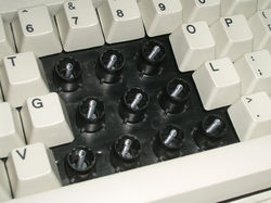
Buckling springs and plastic barrel plate from a Greenock 1996 blue label Model M
- Buckling spring comparison.jpg
A comparison between a Model F hammer & spring (left) and their Model M counterparts (right)
_--_buckling_springs.jpg)
See also
References
- ↑ US Patent 3699296, Richard Hunter Harris, "Catastrophically buckling compression column switch and actuator", issued Oct 1 1972.
- ↑ US Patent 4118611, Richard Hunter Harris, "Buckling spring torsional snap actuator", issued Oct 3, 1978.
- ↑ US patent 4528431, Edwin T. Coleman III, "Rocking switch actuator for a low force membrane contact sheet", filed Oct 3 1983, issued Jul 9 1985.