RAFI RS 74 M SPDT latching
 | |
| Manufacturer | RAFI |
|---|---|
| Family | RAFI RS 74 M |
| Switch type | SPDT latching |
| Sense method | Metal leaf |
| Total travel | ca. 2.5 mm |
| Keycap mount | RAFI mount |
| Switch mount | PCB mount |
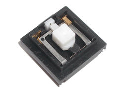
RS 74 M SPDT latching is a combination SPDT/latching switch from the RAFI RS 74 M series. The switch features three terminals: common (front centre), normally open (rear left) and normally closed (rear right). Pressing the switch causes it to toggle which output terminal is connected to the common terminal. The switch can be used as a regular latching switch by not connecting the normally-closed terminal.
No official details are known about the switch.
Design
The shell appears to be identical to that of the illuminated switch, using the right-hand bay to hold a second terminal instead of an LED. The bottom of the shell is marked ".512" but this may be the shell part number, since the shell part numbers don't seem to correspond to switch part numbers.
Based on small catalogue photos, the latch mechanism appears to be the same as that found in other RAFI RS 74 and RS 76 switches. Due to the size of the RS 74 switch, with the basic shell at 5.6 mm tall, or 6 mm including the standoff rails (half that of a Cherry MX switch) the latch mechanism must be very small. Unusually, it features a slide block; whereas Alps SKFL Lock places the cam track in the slider, this switch places the cam track in the slide block. The slider features a spring-loaded pin that follows the cam track. While Alps SKFL's follower pin is supported by a large plate spring, RAFI opted for a minute helical spring, 2.7 mm long and 0.9 mm in diameter, that sits inside the slider and maintains pressure on the follower pin. Following disassembly, the odds are very high that this spring will become lost.
Until such time that regular RS 74 and 76 switches can be obtained for study, one may reasonably assume that the pictures here are representative of RAFI's latch mechanism.
The contact system itself is also unusual. The normal RAFI flat metal loop is deformed in its normal state: the overhead stationary normally closed contact twists the loop down on its right side. As the slider is depressed, the left side of the loop is pushed down onto the stationary normally open contact, and then the right-hand side of the loop is twisted further to move it down away from the stationary contact.
The action is fairly smooth and precise, with a clear tactile event. Nearly full travel (possibly just short of 2.5 mm) is required to actuate the switch: there is no clear overtravel.
The switch contacts comprise flat gold-plated stationary terminals, and gold-plated hemispheres embedded inside the metal loop, with one hemisphere facing downwards towards the normally open contact, and one facing upwards towards the normally closed contact. The stationary contact terminals are strong, and are twisted by maybe 10° at the point of exit from the shell. The movable contact terminal is extremely weak owing to the particular thinness of the metal loop.
Disassembly
An approximate process is as follows:
- Push up on the normally closed terminal to ease the contact up enough to allow the loop more vertical movement; it may be possible to remove it at this stage
- Pry out and remove the slide block, a thumbnail may be useful to push it away from the switch shell
- The follower pin will fall out readily; the spring may fall out, or may remain in slider until coaxed out
- Insert the leg from a pair of tweezers leg under the rear of the slider (where it sits in its guide track) and gently lever it out
- The movable contact has a vertical portion above the terminal; this sits underneath the slider guide post, and has to be gently twisted back so that it can be pulled clear and out
- Push up on the normally open terminal until the vertical part of the contact clears the switch shell enough to be gripped and pulled out; if not done already, the normally closed terminal can also be removed
- Using pliers, some cloth to prevent scuffing and a strong grip, apply sufficient pressure and effort to remove the slide block track block; this block is fitted so tightly that it cannot be reinserted
Gallery
Top, in normal state

Top, in latched state

Linear illuminated switch, for comparison

Bottom; the ".512" marking likely does not denote the part number

Slide block fully left, during the operating cycle

Slide block partially removed

Slide block fully removed

Slide block track block removed

Slide block, front view

Slide block, rear view

Disassembled, bottom views; only nine parts are shown

Disassembled, top views; all ten parts are shown

Length of the small spring

Detail of the small spring


