Hmmm, I never tried plugging two Teensies into one PC (I only use one per keyboard like most folks), but wouldn't you be fine as long as you only press Reset on one of them at a time? I don't think the Teensy programmer makes a fuss about active devices, those should look like regular USB devices.PJE wrote:Has anyone had experience having two teensy modules connected to a single PC. I'd like to be able to program both units without the constant plugging and unplugging...
[WIP] OneHand - 20% Keyboard
-
JBert
- Location: Belgium, land of Liberty Wafles and Freedom Fries
- Main keyboard: G80-3K with Clears
- Favorite switch: Capacitative BS
- DT Pro Member: 0049
-
Muirium

- µ
- Location: Edinburgh, Scotland
- Main keyboard: HHKB Type-S with Bluetooth by Hasu
- Main mouse: Apple Magic Mouse
- Favorite switch: Gotta Try 'Em All
- DT Pro Member: µ
I just tried a couple of Teensies at once, and JBert is exactly right: the Teensy loader app only pays attention to Teensies in program mode (when you hit the reset button or trigger it in your own code). Other Teensies are ignored. So just entrance one of them at a time!
As for SA profile caps, here's my OneHand (still not soldered so a little wonky looking) with uniform profile row 3 SA caps on it instead:
Vierax is right about the profiles I used in my earlier picture. I can't really vouch for how they feel (as the keyboard's quite topsy turvy waiting on assembly) but I'd guess the "right" rows would feel better. They certainly have the look.
Doubleshots like these are no good at letting light through. (And none of Round 5 has LED windows.) This is what they look like when backlit:
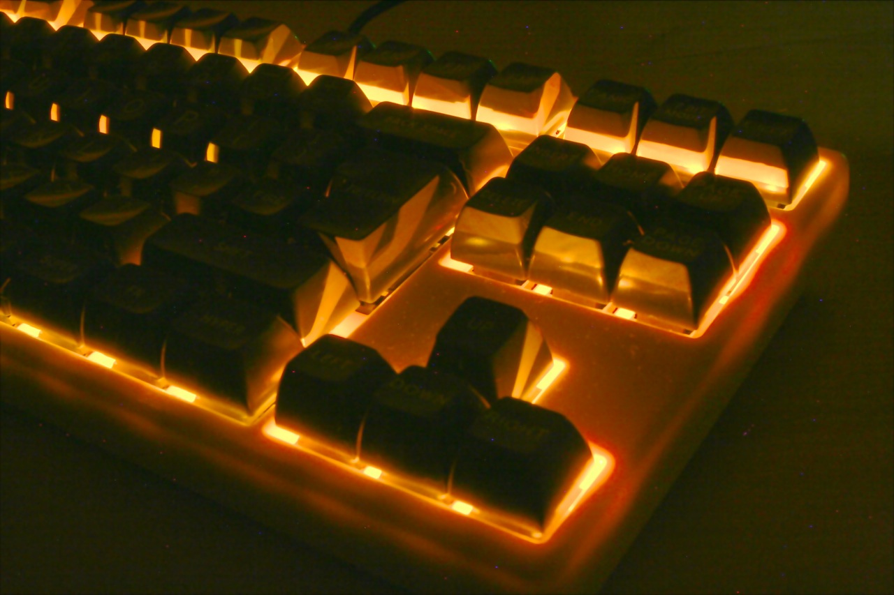
Otherworldly! If not exactly informative.
As for SA profile caps, here's my OneHand (still not soldered so a little wonky looking) with uniform profile row 3 SA caps on it instead:
- IMG_9774.JPG (890.98 KiB) Viewed 13213 times
- IMG_9775.JPG (811.76 KiB) Viewed 13213 times
- IMG_9776.JPG (877.02 KiB) Viewed 13213 times
Doubleshots like these are no good at letting light through. (And none of Round 5 has LED windows.) This is what they look like when backlit:
Otherworldly! If not exactly informative.
-
clickclack123

- Location: Australia, mate!
- Main keyboard: CM Storm Quickfire TK
- Favorite switch: Cherry MX Brown
- DT Pro Member: -
I haven't but I have seen usb hubs on ebay with switches for each port. Maybe you could use one of those?PJE wrote:Has anyone had experience having two teensy modules connected to a single PC. I'd like to be able to program both units without the constant plugging and unplugging...
-
PJE

- Location: Michigan, USA
- Main keyboard: Happy Hacking 2 Lite
- Main mouse: Microsoft 4000
- DT Pro Member: -
Thanks for all the input. I'll try it this afternoon when I get back to the project. First task is a more reliable link - I used a random collection of 0.1in components which are not designed to be together, including the ribbon cable from an old Grayhill encoder...
I'm going to create a simple protocol between the two halves, where the second keyboard sends data on key change and is optionally returned the LED pattern. There will probably be a message once or twice a second to ensure synchronization, but otherwise it will send data as only the rows that have changed with 3-bits of control data indicating the row, and 5-bits for the buttons.
Once this protocol is running in the second unit, there should be no need to keep changing the code, and the switch from one to two hand would be a mode change in the USB section triggered by the receipt of an I2C message from the second keypad.
I'll also be putting together an assembly guide, outlining the necessary and optional steps.
-
PJE
- Location: Michigan, USA
- Main keyboard: Happy Hacking 2 Lite
- Main mouse: Microsoft 4000
- DT Pro Member: -
Things are taking a little longer than expected...
The second keyboard sends I2C messages to the main unit using the following binary encoding:
R R R K K K K K - where R is the row number 1..4, and K are the individual switches.
If one row changes then only one byte is sent to the main unit, and all changed rows are sent as needed. Every 0.5s of inactivity the second keyboard sends the current status of all the rows to keep the two keyboards synchronized. I have used 001, 010, 011 and 100 for the R value. I therefore have a number of free values for options such as request mode LED values.
As chording is less likely with the TwoHand arrangement, I'm changing the keyboard scanning logic to output keypresses like a more standard keyboard, which will allow much quicker typing as the system does not need to wait for the switches to settle.
I now have code which scans all the switches and generates a debounced matrix of keyswitches. I now need to convert them into the scan codes.
After blaming the 0.1" ribbon cable, I found the problem to be a dry joint on the 0.1" header. I only found this after soldering a ribbon cable in place... :0(
-
PJE
- Location: Michigan, USA
- Main keyboard: Happy Hacking 2 Lite
- Main mouse: Microsoft 4000
- DT Pro Member: -
I threw out most of my OneHand code and created standard keyboard code. I can now type two handed, using the thumb keys to select layers... I now need to look at optimized layouts.
I have a little bit of tweaking to do on the thumb space code, and optimizing the function layers. I need to be able to type space easily while not getting in the way of the layers.
Now I need to find a way to get the third unit in play... ThreeHand!
I have a little bit of tweaking to do on the thumb space code, and optimizing the function layers. I need to be able to type space easily while not getting in the way of the layers.
Now I need to find a way to get the third unit in play... ThreeHand!
-
PJE
- Location: Michigan, USA
- Main keyboard: Happy Hacking 2 Lite
- Main mouse: Microsoft 4000
- DT Pro Member: -
I have finally finished a first draft of the OneHand assembly guide which can be downloaded from this link - http://www.creativephotoeffects.com/pje ... _Guide.pdf. It shows the basic order in which the keyboard is put together.
I've also mounted both of my newly assembled OneHand's (Red & Brown) on a (crude) Plexiglas plate to create a TwoHand keyboard. The sticky feet and fixed arrangement make it easier to use. Here are some pictures.


I'm working on the TwoHand code at the moment. I have it working as a basic keyboard which alpha-numeric and cursor movement, but need to work more on functions and symbols.
I'm also looking to design a 3D printed base for the OneHand and TwoHand once my V2 design is finalized. I'm thinking for the TwoHand a small triangular PCB in the V between the keyboard halves could hold a couple more thumb keys and also some form of mouse replacement (Parallax OFN, Trackpoint, etc).
Now if I wasn't so busy at work...
I've also mounted both of my newly assembled OneHand's (Red & Brown) on a (crude) Plexiglas plate to create a TwoHand keyboard. The sticky feet and fixed arrangement make it easier to use. Here are some pictures.
I'm working on the TwoHand code at the moment. I have it working as a basic keyboard which alpha-numeric and cursor movement, but need to work more on functions and symbols.
I'm also looking to design a 3D printed base for the OneHand and TwoHand once my V2 design is finalized. I'm thinking for the TwoHand a small triangular PCB in the V between the keyboard halves could hold a couple more thumb keys and also some form of mouse replacement (Parallax OFN, Trackpoint, etc).
Now if I wasn't so busy at work...
-
kile
- Location: Hungary
- Main keyboard: Steelseries 7G Wireless
- Main mouse: Razer DeathAdder Leftie
- Favorite switch: Cherry MX Green
- DT Pro Member: -
I really like that layout and I think it would be perfect for a wireless gamepad I want to make. I want to keep the layout but design a new circuit which would work with a nRF24LE1 module instead of a Teensy. If the routing doesn't turn into a nightmare, I also want to try to add a USB connector which would power backlighting LED's. So, the keyboard would work in wireless mode all the time, but you could plug it into USB to turn on the Las Vegas mode  That way you have long battery life, but backlighting too.
These modules are quite cheap (7$ shipped) but need dedicated programmers. The programmer is easy to make and the parts cost about 10$.
And of course I would need a battery to power the module, but I think a Lithium cell battery should be able to give a few weeks to a few months of charge.
The USB dongle would be a nRF24LU1+ which go for about 10-20$ on ebay depending on model and can be programmed with the same programmer as the keyboard controller module. And the firmware for that is already ready and waiting.
Do you have KiCad or Eagle files of your V1 PCB? Can you please send them over to me, so I don't have to start from scratch. Thanks!
-
PJE
- Location: Michigan, USA
- Main keyboard: Happy Hacking 2 Lite
- Main mouse: Microsoft 4000
- DT Pro Member: -
Hi Kile,
Unfortunately I use a commercial PCB package called EasyPC which I doubt can provide output (other than Gerber or DXF) which can be used with KiCad. I can provide the schematic, but it's simply each switch with one pin to 0V and the other to a CPU input pin... which would need to be remapped if you use a different CPU.
Your wireless suggestion is very interesting. I'll take a look at the nRF24LE1 and nRF24LU1+ as options for the V2. I was looking at Bluetooth, but the cost was getting a little out of hand.
-
kile
- Location: Hungary
- Main keyboard: Steelseries 7G Wireless
- Main mouse: Razer DeathAdder Leftie
- Favorite switch: Cherry MX Green
- DT Pro Member: -
That's too bad. But it's no problem, I'll just have to find KiCAD Cherry footprints and recreate the layout. It just means a little more work. I don't really need the schematic, because almost everything will have to change. But thanks.
-
clickclack123
- Location: Australia, mate!
- Main keyboard: CM Storm Quickfire TK
- Favorite switch: Cherry MX Brown
- DT Pro Member: -
I tried nRF24L01+ (super cheap boards from china) at home with two Arduino nanos, and it was super flaky. I just ran a ping test program, and even when they were only separated by 1m, 95% of pings weren't returned. I assume they do work, but I couldn't get them working reliably at all. If they didn't work at all, I would have thought that I did something wrong, but since 5% of pings were returned, I had to assume there was something wrong with the transmitters/receivers.PJE wrote:Hi Kile,
Unfortunately I use a commercial PCB package called EasyPC which I doubt can provide output (other than Gerber or DXF) which can be used with KiCad. I can provide the schematic, but it's simply each switch with one pin to 0V and the other to a CPU input pin... which would need to be remapped if you use a different CPU.
Your wireless suggestion is very interesting. I'll take a look at the nRF24LE1 and nRF24LU1+ as options for the V2. I was looking at Bluetooth, but the cost was getting a little out of hand.
I'd like to hear from someone who has gotten them to work well though.
-
Muirium
- µ
- Location: Edinburgh, Scotland
- Main keyboard: HHKB Type-S with Bluetooth by Hasu
- Main mouse: Apple Magic Mouse
- Favorite switch: Gotta Try 'Em All
- DT Pro Member: µ
What about antennas? (I know nothing about these boards, just a guess.)
One time a friend bought a second hand iBook that had the weakest WiFi. It worked, but with very poor signal strength and noticeable performance issues when browsing. I discovered that it was doing this drspite the internal WiFi antenna not being clipped correcty to the AirPort card. Those old ones clicked twice when you pushed it in. The moral of the story: antenna! Can live without them, but not painlessly.
One time a friend bought a second hand iBook that had the weakest WiFi. It worked, but with very poor signal strength and noticeable performance issues when browsing. I discovered that it was doing this drspite the internal WiFi antenna not being clipped correcty to the AirPort card. Those old ones clicked twice when you pushed it in. The moral of the story: antenna! Can live without them, but not painlessly.
-
kile
- Location: Hungary
- Main keyboard: Steelseries 7G Wireless
- Main mouse: Razer DeathAdder Leftie
- Favorite switch: Cherry MX Green
- DT Pro Member: -
I've used them for about two years for various projects and I've had only good experiences with them. I have had one in my keyboard since last summer and it's working quite well, even though the keyboard PCB is shielding the transmitter. I've built a transmitter module for a toy helicopter with one of these cheap Chinese nRF24L01+ modules with a PCB antenna and it worked reliably at a distance of about 80 meters. The helicopter had a good receiver antenna though, I was not able to achieve anything close to that with the keyboard.
There could be a number of reasons why it didn't work for you. Most probably you were using a channel which was in use by some WiFi or Bluetooth device (channels 0-80). Or maybe you just had a dud module.
There could be a number of reasons why it didn't work for you. Most probably you were using a channel which was in use by some WiFi or Bluetooth device (channels 0-80). Or maybe you just had a dud module.
-
clickclack123
- Location: Australia, mate!
- Main keyboard: CM Storm Quickfire TK
- Favorite switch: Cherry MX Brown
- DT Pro Member: -
These boards just have an antenna in copper on the pcb, so they should be connected ok.Muirium wrote:What about antennas? (I know nothing about these boards, just a guess.)
One time a friend bought a second hand iBook that had the weakest WiFi. It worked, but with very poor signal strength and noticeable performance issues when browsing. I discovered that it was doing this drspite the internal WiFi antenna not being clipped correcty to the AirPort card. Those old ones clicked twice when you pushed it in. The moral of the story: antenna! Can live without them, but not painlessly.
Wow! 80m! I'll have to have another go with them, or try buying another pair. They're so cheap it's worth it. Can you find me an ebay link to the module that you have? The one I had looked like the attached pic.kile wrote:I've used them for about two years for various projects and I've had only good experiences with them. I have had one in my keyboard since last summer and it's working quite well, even though the keyboard PCB is shielding the transmitter. I've built a transmitter module for a toy helicopter with one of these cheap Chinese nRF24L01+ modules with a PCB antenna and it worked reliably at a distance of about 80 meters. The helicopter had a good receiver antenna though, I was not able to achieve anything close to that with the keyboard.
There could be a number of reasons why it didn't work for you. Most probably you were using a channel which was in use by some WiFi or Bluetooth device (channels 0-80). Or maybe you just had a dud module.
- Attachments
-
- sku085222-5.jpg (168.26 KiB) Viewed 12088 times
-
PJE
- Location: Michigan, USA
- Main keyboard: Happy Hacking 2 Lite
- Main mouse: Microsoft 4000
- DT Pro Member: -
I was looking at the same module. The main issue is the 3.3V power and the use of SPI for communication which would require a modification to the schematic.
I've been busy with work, and also playing with a couple of new dev boards from Xmos and Freescale. I have been using the TwoHand keyboard at work to many quizzical looks!
I've been busy with work, and also playing with a couple of new dev boards from Xmos and Freescale. I have been using the TwoHand keyboard at work to many quizzical looks!
-
kile
- Location: Hungary
- Main keyboard: Steelseries 7G Wireless
- Main mouse: Razer DeathAdder Leftie
- Favorite switch: Cherry MX Green
- DT Pro Member: -
Yes, that's the module I have in my keyboard and the same I used for the helicopter. They are all over ebay. I bought 10 of these a while ago for about $12 shipped.
-
kile
- Location: Hungary
- Main keyboard: Steelseries 7G Wireless
- Main mouse: Razer DeathAdder Leftie
- Favorite switch: Cherry MX Green
- DT Pro Member: -
First of all, I apologize for hijacking PJE's thread. If it's a problem - I will make my own, but I thought this belongs here, since this is PJE's layout and design.
So, I've started working on the wireless version of the PJE's OneHand layout. Because of EagleCAD's board size limitations I've had to learn to use KiCad which was a pretty pleasant experience. On the whole I think it's a much better package than EagleCAD even not taking the Eagle's limitations into consideration. This is what I've got so far:
This image is from an amazing piece of software called ZofZPCB. It takes the gerber files as input and creates a rotatable 3D representation of the finished PCB. It really is amazing.
I am using the smaller CR1632 coin cell (upper left corner, under that SMD mosfet) because I could not fit the CR2032 on the board. I have a reverse polarity protection MOSFET and a through-hole mini USB socket for powering the LEDs. I've also added a breakout for programming the nRF and a breakout for UART.
I've made all the components through-hole to make it easier to assemble. The only exception is the MOSFET, but that shouldn't be hard to solder.
I still have to double check the component footprints, and think of where to put to mounting holes. Then I'll send the gerbers to a PCB fab. And then I'll start working on the firmware.
I've attached the KiCad files of the board and schematic. I used the latest version, so you might have to upgrade if you want to open the files. I will probably make a google code project later on.
All comments are more than welcome.
So, I've started working on the wireless version of the PJE's OneHand layout. Because of EagleCAD's board size limitations I've had to learn to use KiCad which was a pretty pleasant experience. On the whole I think it's a much better package than EagleCAD even not taking the Eagle's limitations into consideration. This is what I've got so far:
- far from finished...
- OneHandWirelessFront.png (200.83 KiB) Viewed 10796 times
I am using the smaller CR1632 coin cell (upper left corner, under that SMD mosfet) because I could not fit the CR2032 on the board. I have a reverse polarity protection MOSFET and a through-hole mini USB socket for powering the LEDs. I've also added a breakout for programming the nRF and a breakout for UART.
I've made all the components through-hole to make it easier to assemble. The only exception is the MOSFET, but that shouldn't be hard to solder.
I still have to double check the component footprints, and think of where to put to mounting holes. Then I'll send the gerbers to a PCB fab. And then I'll start working on the firmware.
I've attached the KiCad files of the board and schematic. I used the latest version, so you might have to upgrade if you want to open the files. I will probably make a google code project later on.
All comments are more than welcome.
- Attachments
-
- ED_board.zip
- (37.82 KiB) Downloaded 217 times
-
PJE
- Location: Michigan, USA
- Main keyboard: Happy Hacking 2 Lite
- Main mouse: Microsoft 4000
- DT Pro Member: -
Hi kile, no problem with hijacking the thread. Post away!
Love the design idea. I'm considering moving the outside columns down on the V2 design to line up with the center column to keep my thumb and little finger more centered on the home keys. The current layout is still pretty good for my hand size though.
Your placement of the RF module is clever, I'd recommend ensuring no ground plane covers the on board antenna.
I'm considering an optimized TwoHand design, allowing me to free up the two OneHand units for further experimentation.
Work has been crazy recently, so I haven't had as much time as I would have liked to work on the project. I'm going to have to find some time, but all the excellent designs on Deskthority and Geekhack keep my mind racing...
-
kile
- Location: Hungary
- Main keyboard: Steelseries 7G Wireless
- Main mouse: Razer DeathAdder Leftie
- Favorite switch: Cherry MX Green
- DT Pro Member: -
This is the last sanity check before I send the gerbers to the PCB fab.
The LED on SW1:3 can be disconnected from the 5V USB power and connected to an MCU pin and used as a signalization LED for some firmware features (board lock/unlock or layer switcher for instance). Wether the LED is on the 5V or on the MCU can be selected with a jumper (JP1).
I've tried to keep the PCB area around the antenna clear from copper to avoid shielding.
I've added an "external power" source if you want to connect larger batteries. For instance, if there is room in the case you could power the circuit from two AAA which would last much longer than the coin cell battery.
The KiCad files and gerbers can be found on: https://code.google.com/p/onehand-wireless/
Comments and suggestions are welcome!
- PCB front
- onehand-wireless_front.png (302.47 KiB) Viewed 10735 times
- PCB back
- onehand-wireless_back.png (260.4 KiB) Viewed 10735 times
I've tried to keep the PCB area around the antenna clear from copper to avoid shielding.
I've added an "external power" source if you want to connect larger batteries. For instance, if there is room in the case you could power the circuit from two AAA which would last much longer than the coin cell battery.
The KiCad files and gerbers can be found on: https://code.google.com/p/onehand-wireless/
Comments and suggestions are welcome!
-
PJE
- Location: Michigan, USA
- Main keyboard: Happy Hacking 2 Lite
- Main mouse: Microsoft 4000
- DT Pro Member: -
Hi kile,kile wrote:This is the last sanity check before I send the gerbers to the PCB fab.
Comments and suggestions are welcome!
Nice work! The only suggestion I'd make would be to drop a 3.3V regulator powered by true USB connector which would allow the board to be powered from a USB battery pack. Some of these packs are small enough to package with the keyboard and can be recharged as needed.
I'm working on a new TwoHand arrangement with less angle between the two units. I'm looking a creating a V2 PCB for this type of keyboard, maybe offloading the CPU onto a thumb switch board placed between two OneHand matrix PCBs.
-
kile
- Location: Hungary
- Main keyboard: Steelseries 7G Wireless
- Main mouse: Razer DeathAdder Leftie
- Favorite switch: Cherry MX Green
- DT Pro Member: -
Hmmm... Do you mean adding another USB port which would power the LEDs and the controller? Or using the existing USB plug? Either would mean you have to remove the CR1632 battery when you plug in the USB or else the battery might go boom! Also, I don't like regulators for this because all have a quiescant current which is usually about 10 times higher than the controller power consumption. I would be powering the regulator instead of the rest of the circuit. I already have one USB connector which only powers the LEDs, so you can plug the USB battery pack into that and keep the controller powered from a CR1632.PJE wrote:The only suggestion I'd make would be to drop a 3.3V regulator powered by true USB connector which would allow the board to be powered from a USB battery pack. Some of these packs are small enough to package with the keyboard and can be recharged as needed.
I've made another check moments before I wanted to send the files and found a serious problem. I swapped two pins on the module breakout which would need some ugly trace cutting to fix had I not caught it. Phew!
I've never before sent a PCB into production without etching a prototype at home first. I'm a bit nervous...
-
PJE
- Location: Michigan, USA
- Main keyboard: Happy Hacking 2 Lite
- Main mouse: Microsoft 4000
- DT Pro Member: -
For some reason my response never made it to the board...kile wrote:Hmmm... Do you mean adding another USB port which would power the LEDs and the controller? Or using the existing USB plug? Either would mean you have to remove the CR1632 battery when you plug in the USB or else the battery might go boom! Also, I don't like regulators for this because all have a quiescant current which is usually about 10 times higher than the controller power consumption. I would be powering the regulator instead of the rest of the circuit. I already have one USB connector which only powers the LEDs, so you can plug the USB battery pack into that and keep the controller powered from a CR1632.
I was meaning via the USB you had already added. Obviously this comes down to how long the keyboard will work on the CR1632. Did you see if a CR2032 would fit? From my checks it seems to have a better price/power ratio than the smaller cell.
I bought my OneHand PCBs from Seeedstudio for $25. I was very happy with their quality.
-
kile
- Location: Hungary
- Main keyboard: Steelseries 7G Wireless
- Main mouse: Razer DeathAdder Leftie
- Favorite switch: Cherry MX Green
- DT Pro Member: -
My initial idea was to use CR2032, but I couldn't fit it on the PCB that was planned to be 94mm long at the time. Since then I extended it to 99mm to make room for the upper mounting holes, and I didn't check if the CR2032 would fit to the new size. Now I did and it turns out it would fit if I move the serial and the programming interfaces. So, I will delay sending the files another day or so... damn, will this ever end?!PJE wrote:Did you see if a CR2032 would fit? From my checks it seems to have a better price/power ratio than the smaller cell.
Yes, I use ITead. Same factory, same quality. $28.88 shipped for green PCBs.PJE wrote:I bought my OneHand PCBs from Seeedstudio for $25. I was very happy with their quality.
-
kile
- Location: Hungary
- Main keyboard: Steelseries 7G Wireless
- Main mouse: Razer DeathAdder Leftie
- Favorite switch: Cherry MX Green
- DT Pro Member: -
Last night I've changed the battery holder to CR2032, rerouted the top of the PCB and sent the gerbers to ITead. And today I found a small mistake on the board. I wanted the mounting holes to be 3mm, but they turned out to be only 2.5mm. Oh, well... 
I've started designing the case. I want it to have a long wrist rest like on the 7G, and I want it to be made out of wood. And it has to be simple to build and simple to remove the PCB, so I will make it out of two planks of wood and glue them together and then file and sand them down to my linking. I don't have enough tools or knowledge to do everything by myself, so I hope I will find a place where I can have these planks cut to size. But I do have wood files, sandpaper and glue. The PCB will be screwed to the top plank with four screws.
I've installed OpenSCAD (very, very nice piece of software if you know basic programming) and made the design with it. It was surprisingly easy and fun
This is what I want it to look like.
- top plank
- top.png (13.11 KiB) Viewed 10585 times
- bottom plank, the PCB and the top plank underneath
- bottom.png (36.81 KiB) Viewed 10585 times
-
PJE
- Location: Michigan, USA
- Main keyboard: Happy Hacking 2 Lite
- Main mouse: Microsoft 4000
- DT Pro Member: -
Hi Kile,
I like what you're doing... I've been looking into 3D printing a case for my OneHand and TwoHand designs.
At present I'm focusing more on the TwoHand design as I find I can use it easier for typing bulk text. I've been mounting the PCB on a plexiglass base with simple standoffs at the back to clear the CPU module. When using this, some form of wrist rest about 15-20mm thick would make the unit more comfortable to type. I've been using mouse wrist pads in the short term.
I'm working on a new OneHand PCB design which allows a $5 ProMicro to be mounted behind, as with the current design, or to have an additional thumb PCB which can scan the matrix of two OneHand units plus two additional thumb buttons. This version will use a traditional matrix with diodes in a 5x4 arrangement for each hand, using 5x8 matrix scanning for the TwoHand version.
This three PCB arrangement will allow more flexibility in the PCB placement as it can rest flat if needed, and also simplifies the code as only one CPU will be needed.
I like what you're doing... I've been looking into 3D printing a case for my OneHand and TwoHand designs.
At present I'm focusing more on the TwoHand design as I find I can use it easier for typing bulk text. I've been mounting the PCB on a plexiglass base with simple standoffs at the back to clear the CPU module. When using this, some form of wrist rest about 15-20mm thick would make the unit more comfortable to type. I've been using mouse wrist pads in the short term.
- Top.jpg (134.37 KiB) Viewed 10562 times
- Bottom.jpg (169.21 KiB) Viewed 10562 times
This three PCB arrangement will allow more flexibility in the PCB placement as it can rest flat if needed, and also simplifies the code as only one CPU will be needed.
-
PJE
- Location: Michigan, USA
- Main keyboard: Happy Hacking 2 Lite
- Main mouse: Microsoft 4000
- DT Pro Member: -
Well I'm about to kick off my V2 design phase and here's what I'm thinking of:
OneHand
The aim is to allow cursor movement using either thumb without needing too great a reach... Here's hoping!


I'm going to create the new OneHand PCBs first, and then when I've debugged the touchpad and chosen a size, and then finalize the center PCB when I've settled on a spacing. I will then be creating a 3D printed shell to hold the PCBs in the required location, as well as the touchpad carrier.
I now need to track down some DSA keycaps to allow me to have the correct symbols on the caps without worrying about the row style...
Thoughts...
OneHand
- Design pretty much like today, but using a matrix approach rather than the individual pins used on V1.
- Switching from Teensy 2.0 to ProMicro ($5 from eBay) - I'm very happy with the Teensy but I'd like to reduce cost.
- ProMicro can be mounted underneath PCB (as V1), or on a separate PCB.
- Two connection Points for additional thumb keys to provide 20 switches in a 4x5 matrix.
- I2C port available - RJ11/Grove.
- PS/2 Touchpad interface, with data sent via USB.
- Two OneHand modules with rear mounted ProMicros.
- I2C interconnection - RJ11/Grove.
- 2x PS/2 interfaces
- Two OneHand modules without CPU.
- CPU Board holding ProMicro, two additional thumb switches.
- PS/2 Touchpad interface to accept a standard (eBay Synaptics surplus module - I picked up 3 for $3 each).
- Touchpad mounted above CPU, in the V between the keyboard units.
- I2C Interface - RJ11/Grove.
- Two OneHand modules, one with CPU, one without, as mentioned above.
- Center board holding touchpad and two additional thumb switches.
The aim is to allow cursor movement using either thumb without needing too great a reach... Here's hoping!
I'm going to create the new OneHand PCBs first, and then when I've debugged the touchpad and chosen a size, and then finalize the center PCB when I've settled on a spacing. I will then be creating a 3D printed shell to hold the PCBs in the required location, as well as the touchpad carrier.
I now need to track down some DSA keycaps to allow me to have the correct symbols on the caps without worrying about the row style...
Thoughts...