HyperMicro Development
-
matt3o

- -[°_°]-
- Location: Italy
- Main keyboard: WhiteFox
- Main mouse: Anywhere MX
- Favorite switch: Anything, really
- DT Pro Member: 0030
- Contact:
what software do you use?
-
7bit

- Location: Berlin, DE
- Main keyboard: Tipro / IBM 3270 emulator
- Main mouse: Logitech granite for SGI
- Favorite switch: MX Lock
- DT Pro Member: 0001
My own stuff until I get to the .brd and .sch files (including everything but the traces) and kicad from there.

Graphic is kicad's PS output (File/Plot, check "PostScript" and "Real drill" options) and manually put together. But this last step can be done with ImageMagick and a bit of scripting.

Graphic is kicad's PS output (File/Plot, check "PostScript" and "Real drill" options) and manually put together. But this last step can be done with ImageMagick and a bit of scripting.
-
macmakkara

- Location: Finland
- DT Pro Member: -
So that 7bit edition pcb? what about normal ansi or iso?7bit wrote: ↑
-
7bit
- Location: Berlin, DE
- Main keyboard: Tipro / IBM 3270 emulator
- Main mouse: Logitech granite for SGI
- Favorite switch: MX Lock
- DT Pro Member: 0001
ANSI and ISO are the same, because there is no space for a Return key anyway.
Also:
This supports traditional and summetric stggering and 3 sizes of space bars (1, 4 and 7 units). Except for the 6.25 units space bar and an extra key, you can have about the same layout as the JD40.
I will post possible layouts later.
Another advantage over the JD40 is the fact that you can use PCB-mount switches and stabilisers to cheap out on a mount plate and save weight!
However, mount plates for plate mounted Cherry stabilisers will be available, too.
ps: might be even possible to add support for 6.25 units Cherry space bars ...

-
webwit

- Wild Duck
- Location: The Netherlands
- Main keyboard: Model F62
- Favorite switch: IBM beam spring
- DT Pro Member: 0000
- Contact:
The real important question is, does it have full qHACK support now?
-
rindorbrot

- Location: Bavaria, Germany
- Main keyboard: Phantom, GON NerD 2.0 TKL
- Main mouse: Zowie ZA11
- Favorite switch: MX Ergo-Clear, Nixdorf Soft-Touch
- DT Pro Member: 0029
Wasn't the qHACK a variant for the 60% HyperMini? The HyperMicro is the 40% board...
-
webwit
- Wild Duck
- Location: The Netherlands
- Main keyboard: Model F62
- Favorite switch: IBM beam spring
- DT Pro Member: 0000
- Contact:
You are right, I am mistaking. This would suggest 7bit has his priorities wrong!
-
7bit
- Location: Berlin, DE
- Main keyboard: Tipro / IBM 3270 emulator
- Main mouse: Logitech granite for SGI
- Favorite switch: MX Lock
- DT Pro Member: 0001
Done:
- support for lots of staggerings
- holes for trackpoint
- controller moved to top-row
Todo:
- support for 6.25 units space bars to kill GH's JD40 keyboard
- support for 3 mouse-buttons at the bottom to please the wild duck
- support for lots of staggerings
- holes for trackpoint
- controller moved to top-row
Todo:
- support for 6.25 units space bars to kill GH's JD40 keyboard
- support for 3 mouse-buttons at the bottom to please the wild duck
-
scottc

- ☃
- Location: Remote locations in Europe
- Main keyboard: GH60-HASRO 62g Nixies, HHKB Pro1 HS, Novatouch
- Main mouse: Steelseries Rival 300
- Favorite switch: Nixdorf 'Soft Touch' MX Black
- DT Pro Member: -
What about the scroll wheel?!
Scroll wheel should always be implemented as middle click + trackpoint drag, though.
Scroll wheel should always be implemented as middle click + trackpoint drag, though.
-
7bit
- Location: Berlin, DE
- Main keyboard: Tipro / IBM 3270 emulator
- Main mouse: Logitech granite for SGI
- Favorite switch: MX Lock
- DT Pro Member: 0001
Scroll-wheel should go at the positions of the center-bottom-switch (the one that would be used for a 4 or 7 units space bar).
I think I should add a 2nd controller for all those extras ...

I think I should add a 2nd controller for all those extras ...


-
Muirium

- µ
- Location: Edinburgh, Scotland
- Main keyboard: HHKB Type-S with Bluetooth by Hasu
- Main mouse: Apple Magic Mouse
- Favorite switch: Gotta Try 'Em All
- DT Pro Member: µ
ANSI400 looks quite nice, but I have one (possibly impossible) request:

HHKB style 1u Fn key on the right of right Shift, plz. And I mean at the right edge of the keyboard. 1.25u ain't quite the same.
SYM400 has it. And its symmetry is growing on me the more I look at it:

1.25u mods are cooler, but I'll have a lot of 1.5u caps spare from Round 5 anyway, so…
HHKB style 1u Fn key on the right of right Shift, plz. And I mean at the right edge of the keyboard. 1.25u ain't quite the same.
SYM400 has it. And its symmetry is growing on me the more I look at it:
1.25u mods are cooler, but I'll have a lot of 1.5u caps spare from Round 5 anyway, so…
-
7bit
- Location: Berlin, DE
- Main keyboard: Tipro / IBM 3270 emulator
- Main mouse: Logitech granite for SGI
- Favorite switch: MX Lock
- DT Pro Member: 0001
Is there any reason not to mount stabilisers upside-down?
I mean such that the wire is between ZXCVBNM<>? and the space bar.
If there is nothing in the way, an upside-down stabiliser would make sure that mousebuttons can be mounted even if a conventional space bar is used.
I mean such that the wire is between ZXCVBNM<>? and the space bar.
If there is nothing in the way, an upside-down stabiliser would make sure that mousebuttons can be mounted even if a conventional space bar is used.
-
scottc
- ☃
- Location: Remote locations in Europe
- Main keyboard: GH60-HASRO 62g Nixies, HHKB Pro1 HS, Novatouch
- Main mouse: Steelseries Rival 300
- Favorite switch: Nixdorf 'Soft Touch' MX Black
- DT Pro Member: -
Well it's much cheaper than a Teensy 2.0 and has enough pins for small boards. It seems like a natural fit to me.
I think I see an error - on the bottom PCB, you have "Teensy 2.0" on both the left and right sides, but on the upper one the Teensy pins are unmarked. Should the "Teensy 2.0" text be on the upper diagram?
I think I see an error - on the bottom PCB, you have "Teensy 2.0" on both the left and right sides, but on the upper one the Teensy pins are unmarked. Should the "Teensy 2.0" text be on the upper diagram?
-
PJE

- Location: Michigan, USA
- Main keyboard: Happy Hacking 2 Lite
- Main mouse: Microsoft 4000
- DT Pro Member: -
With the current price rise of the eBay ProMicro modules, I don't see any reason not to use a Teensy. You're already saving money on the lower switch count.
Personally, I'd ditch the LEDs for this version and look at rotating the overlapping switches 180deg to see if it makes the holes easier to produce.
Love the concept. Keep up the great work..
Personally, I'd ditch the LEDs for this version and look at rotating the overlapping switches 180deg to see if it makes the holes easier to produce.
Love the concept. Keep up the great work..
-
Muirium
- µ
- Location: Edinburgh, Scotland
- Main keyboard: HHKB Type-S with Bluetooth by Hasu
- Main mouse: Apple Magic Mouse
- Favorite switch: Gotta Try 'Em All
- DT Pro Member: µ
Peter's right about the current prices, but in general Pro Micro is a good fit for this sort of project. Much cheaper than Teensy when they're priced right, a bit slimmer, and Micro USB. Here's a blue one for size vs. a Teensy and an NRF wireless controller.
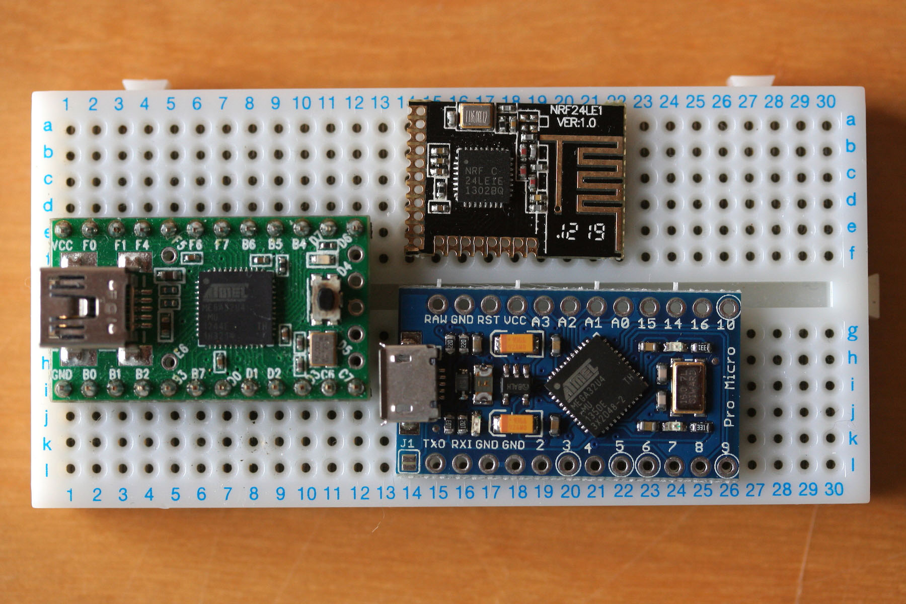
The more you bake in support for, the better!
The more you bake in support for, the better!
-
7bit
- Location: Berlin, DE
- Main keyboard: Tipro / IBM 3270 emulator
- Main mouse: Logitech granite for SGI
- Favorite switch: MX Lock
- DT Pro Member: 0001
Both controllers are on the bottom. Viewed from top, the right one is for the keyboard, the left is for the mouse buttons.scottc wrote: ↑Well it's much cheaper than a Teensy 2.0 and has enough pins for small boards. It seems like a natural fit to me.
I think I see an error - on the bottom PCB, you have "Teensy 2.0" on both the left and right sides, but on the upper one the Teensy pins are unmarked. Should the "Teensy 2.0" text be on the upper diagram?
Indeed, the Pro Micro controller could be used for the mouse-botton PCB.
I use 17 pins, but the Pro Micro seems only to have 16 usable pins.
-
scottc
- ☃
- Location: Remote locations in Europe
- Main keyboard: GH60-HASRO 62g Nixies, HHKB Pro1 HS, Novatouch
- Main mouse: Steelseries Rival 300
- Favorite switch: Nixdorf 'Soft Touch' MX Black
- DT Pro Member: -
I didn't realise that the Pro Micro had so few usable pins. It looks like it has more on the first glance, but most of them are useless. It also seems to have 3 GND pins, which makes no sense to me... disappointing 
-
Igthorn

- DT Pro Member: -
There are 18 usable pins. TX/RX are PD3/PD2. The only ones that are not usable are VCC/RAW/RST/GNDs.7bit wrote: ↑ Indeed, the Pro Micro controller could be used for the mouse-botton PCB.
I use 17 pins, but the Pro Micro seems only to have 16 usable pins.
-
7bit
- Location: Berlin, DE
- Main keyboard: Tipro / IBM 3270 emulator
- Main mouse: Logitech granite for SGI
- Favorite switch: MX Lock
- DT Pro Member: 0001
Thanks, but I'm not sure I want to change anything. I'm working an the LEDs now and want to make sure that at least the switches at the edges can be connected through the PCB.
-
7bit
- Location: Berlin, DE
- Main keyboard: Tipro / IBM 3270 emulator
- Main mouse: Logitech granite for SGI
- Favorite switch: MX Lock
- DT Pro Member: 0001
Does anybody know if I need to connect the VCC-pin to anything on the keyboard?

I've seen it on the Phantom and the ErgoDox, but I'm not sure if it is really necessary.
I've seen it on the Phantom and the ErgoDox, but I'm not sure if it is really necessary.