
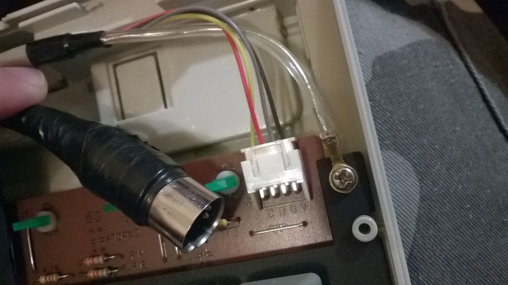
It regards my Focus FK-2002 which has a connector that every once in a while seems to fail, so the keyboard stops registering. It generally works fine, but it's unreliable and that's kind of a deal killer - a shame for such a nice keyboard (especially one in otherwise such an excellent condition), and it deserves being restored to proper functionality. I have to really jam the connector into the adapter (it's not the adapter) and then it works again, but it must've been a clear previous issue because the connector was taped when I got it. The connecting ring even slides back and forth a little bit.
This is the old connector:
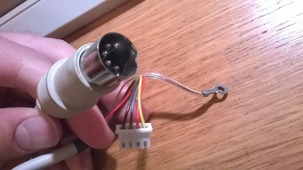
and this is the new one to replace it:
So, presumably I have to do all kinds of testing and tinkering to get this done; where do I start?


