10 May 2013, 23:46
The main thing is just to separate the connections into 'rows' and 'columns' - after that you can just change the firmware to cope with the key mappings.
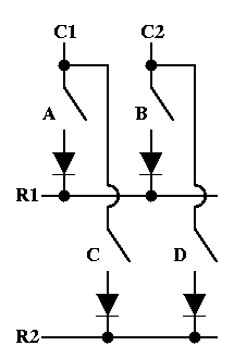
(I put rows and columns in quotes because it's better to think of strobes and senses, in other words, outputs and inputs on the controller).
Start with finding a pin on the connector that connects to a switch pin. Then find all of the other switch pins that connect to that line. Then for each of those switches, find the connector pin that is connected to the other pin of each switch you've just identified. That should give you most if not all of either the strobes or the senses.
To find the other group, you just do a similar thing with one of the lines you found in the first group - find the switches, find the connections for the other pin of those switches.
If you're lucky there will be a pattern, such as strobes being on the left hand pin of each switch, and senses being on the right, which will give some confimation that you got it right, and let you spot any gaps you might still have in your collection of strobes and senses.
As just said, what's missing from that procedure is dealing with the diodes. If you first work out which diode goes with which switch, and which end of it is connected to the switch, you can then treat the switch + diode as just a switch with one pin on the switch, and one on the diode (as in, the two pins of the switch+diode that aren't joined together).
Last edited by
Soarer on 11 May 2013, 00:28, edited 1 time in total.