I think that the only way we can do this is to use a different capacitive pattern than the one used by IBM - one that allows more direct routing of the rows in order to find ways around the tenon holes (where the bolt-mod bolts go). I put some research and thought into it and i'll present some idea here to see what you guys think.
Not all capactive sensors are the same. Not all support a matrix of keys (projected capacitance) and not all that do will accept more than one "touch" at a time. I found lots of "capacitive switch design guides" out there, but few covered the "mutual capacitance" type switch that we need. Two exceptions were design guides from Atmel and STMicroelectronics. Texas Instruments opens their design guide with "Capacitive touch detection is sometimes considered more art than science. This often results in multiple design iterations before the optimum performance is achieved."
First, a look at the model F switch. The top copper consists of two rectangular pads and two small circles. The two circles and the larger rectangle are floating (not connected to anything). The smaller rectangle is connected to a "row". The bottom copper has a rectangle directly under and the same size as the large floating rectangle on the top, but this is connected to a "column". There is also a thick ground trace around all of the traces and pads. The controller sends a signal down one column and that hits all of the rectangles on that one column. Each rectangle forms a capacitive couple with the rectangle above it. and this is picked up by the rectangles connected to the rows (or "sense lines"). How much capacitance is transferred from the column to each row is dependent on if the corresponding pivot plate is up or down - but not significantly impacted by the state of any other switch on the keyboard. This property allows for NKRO. The switch came in two flavors; signal pad on the left or right. The Model M construction method needs bolt holes in the space where the Model F puts "row traces".
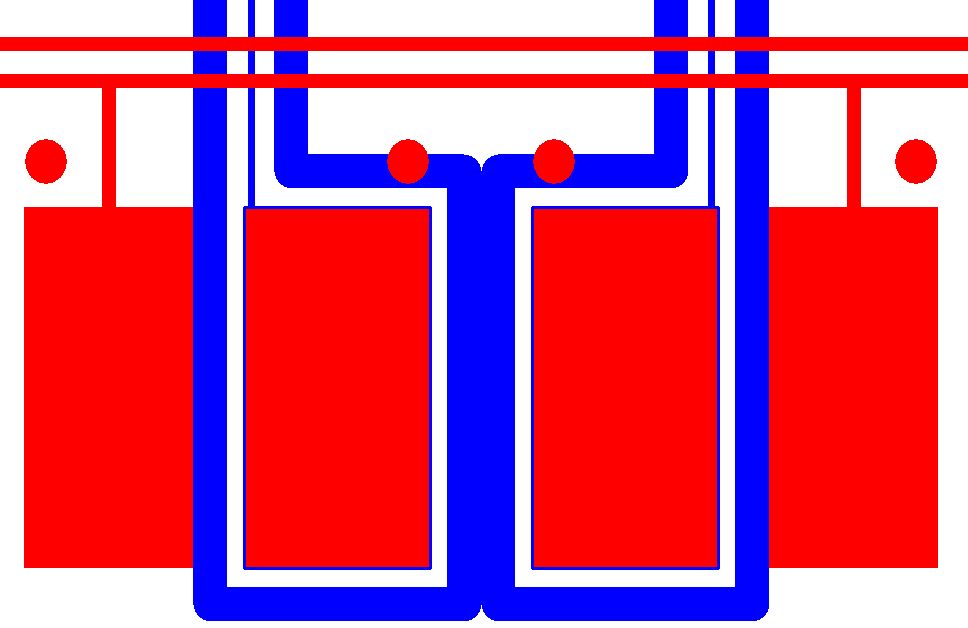
- Red = top, Blue = bottom
- IBM.jpg (52.82 KiB) Viewed 4614 times
Four Triangles
This is probably most similar to the IBM design in that it has a large signal pad on the bottom (now two connected triangles) with a same-size pad floating above it (now two triangles). The sense pad has the same shape, but is rotated 90 degrees so that the shapes intersect in the center of the switch (but on different layers). This pattern is an improvement over the IBM design in that it allows us to route the traces through the pad rather than around them. It also doubles the coupling length between the signal and sense pads (better signal-to-noise ratio). However, the IBM design allowed traces to enter and exit out of three sides whereas this design allows rows to enter and exit out of just the two sides ; columns must enter and exit the top and bottom only.
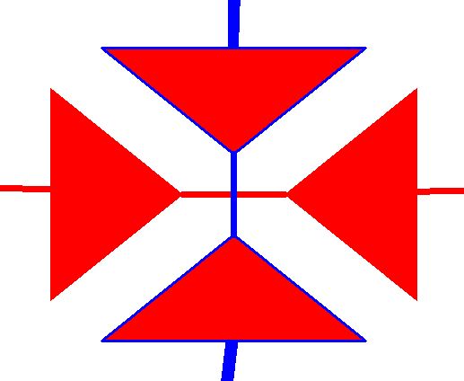
- Red = top, Blue = bottom
- Four Triangles.jpg (20.79 KiB) Viewed 4614 times
Grid and Flood
This design is the most unlike the IBM design. A big flooded sensor pad like on the IBM is more sensitive, but that is not always a good thing. With high sensitivity, the signal can get lost in the noise. The IBM needed the boost in sensitivity because the sensor pad was directly above a big ground plane (the back plate) which reduces sensitivity. One way to reduce the impact of the ground plane is to use the the signal pad as a shield. This design puts the sensor directly above the signal which increases capacitance, but the sensor has less area which reduces capacitance. It has about 10 times the coupling length which means much better signal-to-noise ratio. It also completely opens routing as signal and sense lines can enter or exit from any side and angle.
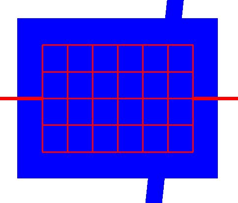
- Red = top, Blue = bottom
- Grid and Flood.jpg (19.74 KiB) Viewed 4614 times
Streets and Canals
This combines elements of the other two designs. It has the flooded signal pad and high coupling length of the "Grid and Flood" and also floating pads like the "Four Triangles" and original IBM. Columns can enter/exit anywhere, but rows can only enter/exit from the middle of the two sides.
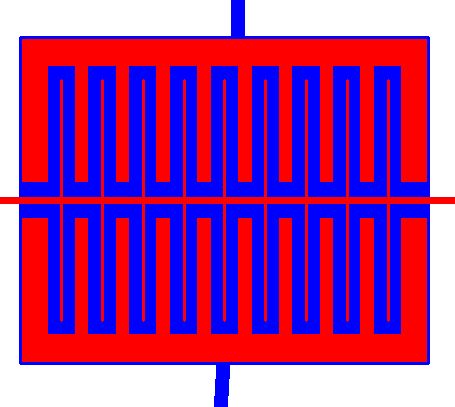
- Red = top, Blue = bottom
- Streets and Canals.jpg (31.33 KiB) Viewed 4614 times
A final design might have 16 columns and 6 rows, like this:
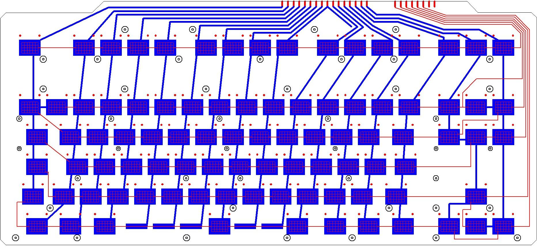
- Red = top, Blue = bottom
- FSSK PCB.jpg (341.63 KiB) Viewed 4614 times
For more info,
https://en.wikipedia.org/wiki/Capacitive_sensing
http://www.atmel.com/images/doc10752.pdf
http://www.st.com/web/en/resource/techn ... 222015.pdf