Custom "75%+1" layout with "Danger Zone" Caps & Dyed Gateron MX Tops

User avatar
richfiles

14 Feb 2016, 20:53

Keyboard75_ProtoCut.jpg
Keyboard75_ProtoCut.jpg (611.69 KiB) Viewed 6078 times
Just gonna say... That was a real pain!
I did this, I guess, because I'm a masochist and enjoy making myself suffer? :roll: :lol:

I cut 88 rectangular 1x3 hole chunks of proto board to be butted against the switch bottom. They will serve as the base that the two SIP pins will be soldered into. I'll assemble the switches with the SIP pins installed, and insert the LED to get the alinement secured so when I solder it, the pins will be in the right position. The reason for 3 positions instead of two, is that the third position gives me an extra pad I can use to allow me to solder a small SMT resistor to each LED.

Also, since I AM adding LEDs, I need one more I/O line to control them. I'll be cutting 4 row wires in the matrix, joining them all together (to the 7th row), and wiring 5 switches to adjacent columns in order to convert the matrix from 14x7 to 13x7. I'm realizing if I had actually planned the matrix out on paper instead of in my head as i wired it, I probably would have caught that bit of efficiency improvement right away. No biggie. It'll be a very minor mod to implement.

User avatar
Corummo

15 Feb 2016, 22:13

richfiles wrote: The reason for 3 positions instead of two, is that the third position gives me an extra pad I can use to allow me to solder a small SMT resistor to each LED.
If LEDs are connected in series, and you split them over 5 rows, you'll just need a resistor for each row, and then to close to GND the other end of the row.
Just like this:
Image
Or do you plan to power them one by one? :o

Anyway, I'm even more amazed by your work. :)

Matt_

15 Feb 2016, 22:28

Wow :shock: Kudos for going through the hassle of wiring all LEDs like that.

The 5V supply won't allow LEDs to be wired in series (or just two of them with a low enough fv, which rules out white & blue LEDs), so the best thing is to wire them in parallel with a resistor each. Or use a constant current driver, but that's more code to implement in software...

User avatar
Corummo

15 Feb 2016, 23:07

OMG! That's a lot of work then.
There are no suitable 5V charge pump LED drivers around? Maxim/Dallas? Ti? Linear? Anybody?

EDIT:
What about MAX1698 and MAX16826?
I started here

User avatar
richfiles

16 Feb 2016, 05:00

It's not a terribly significant increase in work. Rather than wire the LEDs serially, I just wire in parallel. All I have to do is solder a SMD resistor from the middle pad to the side pad, and the LED is between the middle and the other side pad. Then I just have two parallel wires, one attaching to the same side of the LED, and the other attaching to the end of the resistor. That goes across ground and my driver, which just PWMs 5 volts.

Having a resistor per LED makes for very consistent lighting. If there are variances between the LEDs, you can get bright spots with serial wiring. I plan to keep the current draw low enough, so as to allow the entire keyboard, lighting and all, to fall under the 500 mA capacity of USB (I'm actually aiming for under 400 mA, to be not he safe side).

Never actually got to even touch my keyboard today. Totally forgot I'd volunteered to install a smart board at my old school. Oops! Well, at least they got that done! :mrgreen:

User avatar
richfiles

17 Feb 2016, 00:40

Keyboard76_DangerZoneAssembly.jpg
Keyboard76_DangerZoneAssembly.jpg (348.93 KiB) Viewed 5998 times
It's Happening!!!

YES!!! My keys came a day earlier than tracking said they would! :mrgreen:
CRAP!!! My SIP sockets and LEDs and MX top housing removal tools JUST arrived today too! Now I gotta take all the switches apart to install the SIP sockets and LEDs before I can drop the caps on! :cry:

Well, I'm working on it now. I'll take a proper photo tomorrow, set up my grey backdrops outside in the sun for good colors and everything... Once I have the SIP sockets and LEDs installed, and all the keycaps on! 8-)

User avatar
richfiles

17 Feb 2016, 05:05

Keyboard76_DangerZone3RowsLED.jpg
Keyboard76_DangerZone3RowsLED.jpg (586.3 KiB) Viewed 5969 times
I got half the SIP sockets and LEDs installed. As much as I hate to do so, It's 9 pm, I've been at this for quite a few hours now, and my fingers are none too happy about it. If I want any hope of having any fingers functioning at all tomorrow, i think I'll need to call it a night. It's driving me nuts to have the keycaps, and not be ready to install them yet! Still, I'll only make more work for myself if I put it all together, only to have to tear it apart again.
Keyboard76_DangerZoneSipMod.jpg
Keyboard76_DangerZoneSipMod.jpg (360.66 KiB) Viewed 5969 times
Tomorrow, I expect all the LEDs and SIP sockets to be installed. I may have to pop a few off if I have issues with the top housing seating properly. The SIP sockets have to have a notch trimmed for the top housing to fit right. I noticed a pair of switches that were really hard to close. I'll open and re-trim those. Sometimes, the vibration of the cover snapping shut just rotates the SIP socket, so the notched bit no longer lines up. Easy fix, but a thing to watch for when installing these.
Keyboard76_DangerZoneSIP.jpg
Keyboard76_DangerZoneSIP.jpg (496.57 KiB) Viewed 5969 times

User avatar
richfiles

18 Feb 2016, 10:12

Keyboard76_DangerZone.jpg
Keyboard76_DangerZone.jpg (777.85 KiB) Viewed 5959 times
Keyboard76_DangerZoneEnd.jpg
Keyboard76_DangerZoneEnd.jpg (527.96 KiB) Viewed 5959 times
All SIP sockets and LEDs are installed in the switches, and I had to FINALLY install my keycaps! It's BEAUTIFUL!!! I haven't wired the LEDs yet. That's gonna be a weekend project. I hope final wiring is all done by the weekend. Depends if I have a reel of resistors near the value I need. I gotta dig out my box of SMD resistors from the closet and see what I have. Might have to order, but Digi-key always ships fast, since they are so near me.
Keyboard76_SteppedCapsTrim.jpg
Keyboard76_SteppedCapsTrim.jpg (289.47 KiB) Viewed 5959 times
Keyboard76_SteppedCapsStem.jpg
Keyboard76_SteppedCapsStem.jpg (252.99 KiB) Viewed 5959 times
Keyboard76_SteppedCapsEpoxy.jpg
Keyboard76_SteppedCapsEpoxy.jpg (234.85 KiB) Viewed 5959 times
Keyboard76_SteppedCaps.jpg
Keyboard76_SteppedCaps.jpg (189.09 KiB) Viewed 5959 times
Here are pics of the Center Stem Stepped Caps Lock mod I had to do to make it fit. This was far easier than the plate mod. I'll add the light pipe later. I used a 1u "Tab" key as my stem donor, since I had two of them (Number Pad pack and Planck/Atomic pack both included one). Interesting view of the double shot from the wrong side!

User avatar
richfiles

20 Mar 2016, 00:58

Well, quick update. I got the USB port installed. Was simple, but I've been so busy with my two jobs, that I HONESTLY have not touched this keyboard build for a full month. :cry:

Good news, is I'm making progress. I shifted a few diodes over a hair to make room for the tiny LED PCBs, and got all the hardest ones installed. Funny enough, the resistor I needed for the LEDs was only the second part I looked at in an entire unsorted box of resistors! :lol:
Keyboard76_USBslot.jpg
Keyboard76_USBslot.jpg (355.18 KiB) Viewed 5868 times
I used a drill to drill the pilot hole, a modified scroll saw blade as a hand held fine tooth jab saw to square the hole, and a dremel cutting disc to create the slot for the PC board.
Keyboard76_USBinserted.jpg
Keyboard76_USBinserted.jpg (377.99 KiB) Viewed 5868 times
You can see how it fits. The PC board fits the slot, and the Mini USB connector passes through the rectangular opening.
Keyboard76_USBfit.jpg
Keyboard76_USBfit.jpg (236.08 KiB) Viewed 5868 times
Mini USB here! None of that flimsy Micro USB trash! :mrgreen:
Keyboard76_USBscrewed.jpg
Keyboard76_USBscrewed.jpg (430 KiB) Viewed 5868 times
I drilled holes to line up with the PC board's mounting holes. screw diameter above the slot, smaller diameter (so the threads of the screw catch) below the slot, and then I countersunk the hole so the screws sit flush so the bottom cover is not interfered with, clearance wise.
Keyboard76_USBplugged.jpg
Keyboard76_USBplugged.jpg (413.94 KiB) Viewed 5868 times
And as you can see, a Mini USB cable plugs in with plenty of clearance. The socket is nearly flush with the wood surface.

I'll come back with more pictures after the LEDs are wired.

User avatar
LeandreN

21 Mar 2016, 11:11

Looks great man!

User avatar
Ratfink

22 Mar 2016, 13:40

richfiles wrote:Mini USB here! None of that flimsy Micro USB trash! :mrgreen:
Ah, you're confused as to which small USB connector is trash, I see. Hint: Mini-B is rated to 1/10 as many cycles as Micro-B.

User avatar
richfiles

22 Mar 2016, 14:41

I have never had a Mini fail me. Ever. Micro can't claim that. In real world applications, the mechanical durability of the bulkier Mini pays off. It's a keyboard... Why would I be plugging and unplugging all the time? I'll take that mechanical durability and personal experience of having never seen one fail in my life, over the flimsy, wobbly, weakness that is Micro, every day of the week!

User avatar
richfiles

23 Mar 2016, 09:27

Keyboard75+1_LEDsLitBack.jpg
Keyboard75+1_LEDsLitBack.jpg (266.79 KiB) Viewed 5811 times
It's 3+ am, and I'm gonna crash soon, but I DID wanna share progress... I have not laced any of the new wiring yet. LED lighting is a heavier gauge, and is more rigid, thus it won't be laced. After rewiring the matrix from a 7 x 14 matrix to a 7 x 13 matrix, I ended up with a few unlaced new wires. I'll deal with them at the end, when I also lace the wires to the teensy.
Keyboard75+1_LEDsFirstLight.jpg
Keyboard75+1_LEDsFirstLight.jpg (33.99 KiB) Viewed 5788 times
The LEDs are rather dim, but I don't want them to be so bright as to be overpowering. I actually wired the LEDs in series pairs, with a 100 Ω resistor. Each LED only has 8 mA passing through it. Won't even fully max out the USB power limit. It'll be barely a hair over 350 mA for the LEDs.
Keyboard75+1_DriverTrans.jpg
Keyboard75+1_DriverTrans.jpg (401.74 KiB) Viewed 5811 times
I used one transistor to drive the Caps Lock LED, and 4 transistors to each drive 11 pairs of LEDs. I know I'm way under driving the transistors... But they will NEVER get hot. Each 2N3904 is only driving 88 mA, and they're rated to 200 mA. That being said... It's no wonder they get hot when people don't bank their LEDs into separate driven sets! The datasheet I had said 200 mA, so I certainly wasn't gonna try driving all the LEDs from one transistor. I had room and parts, so I just went with 4 banks. The control is all tied together, so one PWM pin on the Teensy can control all 4 banks as a single set of LEDs.
Keyboard75+1_LEDsAlmostDone.jpg
Keyboard75+1_LEDsAlmostDone.jpg (403.54 KiB) Viewed 5811 times
SOOOOOO CLOOOOOSE!!!
I only need to wire the positive supplies to two rows of LEDs, wire the interconnects between the rows and columns to the Teensy, and hook up the 5 wires to my magnetic number pad port.

Soon™

User avatar
richfiles

25 Mar 2016, 10:43

Keyboard75+1_CapsLockLit.jpg
Keyboard75+1_CapsLockLit.jpg (315.33 KiB) Viewed 5782 times
Just dropping this picture here. It looks more red in the pic, but in person, it's more amber.

So, the I2C magnetic serial port is almost wired. I wired a small PC board int he corner so i can desolder the connector wires should I ever need to disassemble it, without wrecking my laced wire runs back to the Teensy 2.0. All the wiring from the PC board to the Teensy is soldered. The LED controller board is now soldered to the Teensy, and all the LEDs are functional, including, obviously, the Caps Lock indicator. The ONLY thing that remains to do physically, is to solder the 7 rows, 13 columns, and to solder the flying leads of the magnetic connector to the small PC board. I'll do that tomorrow, after rate epoxy securing the tiny wires is cured.

That's IT electrically! 8-)

After that, I need to cut and drill and countersink the bottom panel, and add rubber feet. That's all! :D

After that, it's programming... Ugh... Software, the homework of tinkering... :roll:

User avatar
Plasmodium

25 Mar 2016, 11:49

Does this mean you have the link to the numpad figured out now?

User avatar
richfiles

25 Mar 2016, 14:34

I have a sense wire. Internal to the keyboard, the wire is pulled low. When an accessory is attached, the sense wire will be pulled high. All I need to do is monitor the input pin on the Teensy, and if it is high, then execute the code to read the I2C port expander. If the pin is low, then the software would skip executing the I2C code.

What that code would be... ¯\_ :? _/¯
Last edited by richfiles on 25 Mar 2016, 19:57, edited 1 time in total.

User avatar
Plasmodium

25 Mar 2016, 16:44

Haha, fair enough. I don't know much about coding (not from scratch, at least - I can competently edit a TMK layout, though), but something similar to the TMK software for the Ergodox might work? Sure, the halves aren't plug-n-play, but it might be a starting place.

User avatar
scottc

25 Mar 2016, 17:20

Some really good progress here, well done! It should be very rewarding to use this once you're finally finished. I'd definitely go for TMK if I were you, it's fantastic. More difficult to use than some other firmwares like Soarer's, but so much more powerful after you invest that time. Good luck!

User avatar
richfiles

25 Mar 2016, 20:00

I was actually   letting my eyes glaze over at   looking at TMK code. It looks powerful. The big key is figuring out how to selectively poll the I2C bus, ONLY when the sense input is pulled high. :mrgreen:

My only successful C program, to date is a program that generates sine values off a lookup table on an Arduino Mega2560, sends the value to PWM, and then periodically displays the sine value on a display, while rotating which of 8 displays it shows values on (the other displays display all "8.8.8.8.8.8.8.8.". It was a proof of concept for the sine outputs required for my Kerbal controller's hardware navball (an FDAI), and to test some really AWFULL Chinese green seven segment displays, that ended up with a WORSE than 50% failure rate! :o

It was all cobbled from code examples. I am so new to C coding, it's not even funny. The last serious programming I did was on the TI-89 and the Commodore 128... In BASIC! :roll:

I am certainly open to advice, suggestions, and help... 'Specially that last one... Oh dear God help me! :lol:

User avatar
richfiles

27 Mar 2016, 06:58

Keyboard75+1WireLacingFinal.jpg
Keyboard75+1WireLacingFinal.jpg (411.7 KiB) Viewed 5719 times
ALL electrical work is done. Every single wire, solder joint, and part is installed! ᴖᴗᴖ

Now all that remains is to make the bottom cover panel, and program the Teensy! That's all!

A shot of the final completed wiring, as well as the wire lacing. I also have a detail shot of the Teensy 2.0 and the wire lacing for each lead close up. ALL the new wiring is laced with a single cord (again, I use unflavored waxed dental floss). The cord starts in the top right and moves inward toward the Teensy, then it goes down the right side of the teensy, hooks right, turns down again when it hits the LED driver board, follows the bottom edge all the way to the left hand side, turns right, makes a slight detour by the shift key, and then continues up, goes left a key, then back right toward the Teensy, and then binds the left side and bottom of the Teensy. All one piece of string. No cuts, just knotting. Knotting and a LOT of feeding cord through loops! O_o

Enjoy!
Keyboard75+1TeensyLacing.jpg
Keyboard75+1TeensyLacing.jpg (436.08 KiB) Viewed 5719 times

User avatar
richfiles

04 Apr 2016, 00:26

Keyboard75+1_Keyboard_WristRestTop.jpg
Keyboard75+1_Keyboard_WristRestTop.jpg (404.22 KiB) Viewed 5705 times
Here it is... The main keyboard is physically done, and I also went ahead and built a wrist rest for it as well.
Keyboard75+1_BottomPlate.jpg
Keyboard75+1_BottomPlate.jpg (241.15 KiB) Viewed 5705 times
The bottom panel was taken from a 1960s era Phase Angle Voltmeter, just a piece of old test equipment I had in storage. I kinda like the texture.
Keyboard75+1_WristRestStainedSide.jpg
Keyboard75+1_WristRestStainedSide.jpg (308.24 KiB) Viewed 5705 times
The wood was a chunk of free cherry that I got from a friend who works at a cabinet door manufacturer (Elkay). This was a piece they considered "scrap". I guess it had a knot on the edge. I didn't need the whole length. All I know, is it looked good, and was free! :mrgreen:
Keyboard75+1_Keyboard_WristRestDowel.jpg
Keyboard75+1_Keyboard_WristRestDowel.jpg (68.99 KiB) Viewed 5705 times
It had a groove in the tapered edge (for a door panel to insert into), so I bought an oak dowel for $0.89 and painted that with some hobby model paints. The yellow is 3u wide, the same width as the WASD and Arrow clusters.
Keyboard75+1_Keyboard_WristRestFront.jpg
Keyboard75+1_Keyboard_WristRestFront.jpg (335.04 KiB) Viewed 5705 times
Now that construction is 100% complete, all that remains now, is to program it... I'm kinda... Not sure where to start! Any firmware is fine, for now, since I don't yet have a number pad for it. Something easy, that I can program from a Mac. I guess I gotta look at those options now. In time, i'll get a plate for the number pad and add it. I'll revisit the firmware at that point to enable the hot swap functionality. For now, I want NOW functionality of what I have made! ;)

User avatar
richfiles

04 Apr 2016, 09:42

Keyboard75+1_Schematic.jpg
Keyboard75+1_Schematic.jpg (333.05 KiB) Viewed 5688 times
This is my schematic. I could have designed it better, but honestly, this worked out. If I had to do it again, I'd probably try to do something a little more logical.

I need to take a break. Spent all day trying to figure out firmware... It's 2:30 am now... Ugh... I don't even know which one I should use! :?

I need future I2C expandability (using a port expander), so even if a firmware is easier than another, I imagine I should still stick with something that's more capable, so I don't have to redo everything with new software when I make the number pad. I am SO not good with software...

I was thinking, regarding number pad hot swapability, if I make the I2C writes and reads only occur when an input pin state is high... skipping a portion of the scan, and returning no results when low... would that work? I'm not exactly at the point yet where I need that yet, but I should think about it.

I was looking at TMK, but I swear it's making my brain spin! :roll:

User avatar
richfiles

18 Apr 2016, 23:02

Keyboard_DZ_75+1_Top.jpg
Keyboard_DZ_75+1_Top.jpg (411.13 KiB) Viewed 5650 times
I just wanna thank everyone here who have been complementing this build and singing it's praises! Epic thanks! :mrgreen:
DangerZone_NewMasterArm_Bumps_Fallout.jpg
DangerZone_NewMasterArm_Bumps_Fallout.jpg (122.65 KiB) Viewed 5650 times
So, Signature Plastics has started sending out replacement keys for the errors made in the Danger Zone production. Minor issues that don't much affect me, but certainly issues that have bothered others (no homing nipple/bump keys, Master Arm key the wrong color). Haha! That blue Master Arm key is a trophy to me! Proof of it being a first run! 8-)

Also, major thanks to UsualSuspectXXX, from over at geekhack for selling me those Fallout keys. They make SUCH A GOOD PAIRING with Danger Zone! He had some trades to offer/sell. I figure since he helped me get some keys I'd wanted for a while now, I'll offer him a hand and link back to where I got them! :D
https://geekhack.org/index.php?topic=77714

I'll also be getting these keys as well. Everyone knows they need Vault and Mini-Nuke keys! :ugeek:
group-buys-f50/out-of-the-vault-the-meg ... 13506.html
Keyboard_DZ_75+1_Side.jpg
Keyboard_DZ_75+1_Side.jpg (436.78 KiB) Viewed 5650 times
As for the keyboard... I STIIIIIILL don't have it programmed. I've just been so busy, and I'm so new to the software side of things, that I've just not really sat down to start or even figure out what I need to do... Lord help me! It's not TTL/CMOS BOOLEAN LOGIC!!! Wat do I do with code! :roll: :lol:

User avatar
richfiles

28 Jun 2016, 06:36

Well... Update, work has had me swamped, and it gets no better in the next couple weeks. I STILL have yet to figure out how to program the thing, and I still have not spotted a group buy that I can get the plate for the number pad made. :( Since I want extra keys on my number pad, I can't really buy a stock number pad plate. I was thinking a 6x6, with a 2u "0", 2u "Enter", 1u "+", and possibly some 1.25u or 1.5u in the top row. That and I need the dimensions to fit my existing plate's height, screw hole spacing, and corner radius. Blue anodizing is an obvious must.

I really wanna get this finished, but either I'm missing plate group buys (that let you do custom plates), or there haven't been any since LeandreN's custom group buy last year. I don't know. I've been so busy lately. Ugh...

I can't believe I still have no idea how to program this thing... :?

Morituri

30 Jun 2016, 19:48

The 6kRO vs NkRO issue is not a limitation of the Apple OS.

Keyboards have to come up in a "Boot Mode" (where the BIOS knows how to run them) before the OS loads. In Boot Mode they transmit packets limited to 8 bytes. They use one byte for modifier bits, one byte is reserved, and that leaves 6 bytes each of which has an 8-bit keycode to report which non-modifier keys are currently depressed. The result is that a keyboard in boot mode cannot report more than six simultaneously pressed keys.

One of the things that the OS does during bootup is to query the boot-mode USB devices about what report format they'd prefer to be making, and they respond with a description of how to interpret their reports in the future. At this point a USB keyboard COULD say, "I want to submit a 16-byte report format, 14 bytes of which can contain keycodes" and switch to 14kRO. Since most people have only 10 fingers, (well, okay, 8 and 2 thumbs) it would be pretty safe to claim NkRO for that keyboard; not technically correct exactly, but no human typist could prove you wrong unless they were polydactyl.

The problem with this theory is that it's easier and less code to program a keyboard controller that only knows one mode, the Boot mode report format is "good enough" for all purposes major manufacturers think they're actually making keyboards for, and the major manufacturers are lazy. And therefore the major manufacturers' USB keyboards, when they get the OS message that says "what's your report format?" just tell the system they're reporting exactly the same report format they used in boot mode, and the operating system just says, "Okay, 6kRO it is."

There is no current OS that fails to give keyboards a chance to switch to a different report format, or which fails to decode a different report format if the keyboard controller tells it to.

User avatar
richfiles

01 Jul 2016, 02:16

Nice detailing on how the protocol works. I was aware of the basics, but not the details...

Naw, my issue is I just have next to no programming experience in C, and I've just not had the time to sit down with one of the "firmwares" and figure out how to customize it to my specific keyboard... I know... pathetic... :? All this mechanical and electronic work, and in the end, my eyes cross trying to make heads or tails out of something that ought to be not nearly that hard at all. I mean, that's why those firmwares exist, to simplify this part. To have the actual code pre-made.

Swapped shifts, being down a person for 2 straight weeks... It's just shutting my brain down! 2 months... 2 months, and I've barely gotten anything, for any of my projects done!

Well, I opened another TMK guide... Maybe I can finally git gud and git thru it. :roll:

User avatar
richfiles

21 Jul 2016, 03:51

I think I'm about half way through the TMK tutorial. I've assigned my pins, and defined my matrix (okay, I have two definitions, electrical and physical layouts, and am awaiting a reply on whether either is a valid application of code). After that, I think I define the layers... Getting there!

User avatar
richfiles

23 Jul 2016, 20:06

So, here's my progress so far. Also, as a disclaimer, I posted this info, in nearly the same format, on the TMK tutorial/help thread. I'm hoping to get a response to my coding questions. I feel this info should also be here, so this thread will maintain a complete record of the build and coding.

First, I've made up a nice layout worksheet that has all the electrical rows and columns identified not he physical layout. It's top down view, so it'll be useful for defining my key layout too.
Keyboard_DZ_75+1_Matrix.png
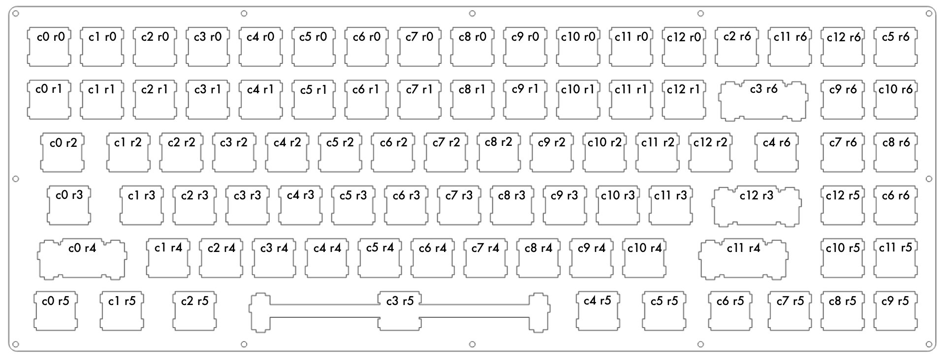
Keyboard_DZ_75+1_Matrix.png (69.07 KiB) Viewed 5478 times
So, I did start with the TMK firmware. If it can do everything I need it to do, then I'll stick with it, but there's always the option of re-flashing it with something else in the future if I can't integrate the hot swappable port expander functionality into the code. The code for my Column and Row pin definitions are below:

Code: Select all

/* Column pin configuration
 * col: 0   1   2   3   4   5   6   7   8   9   10  11  12
 * pin: F0  F1  F4  F5  F6  D4  D5  D2  B7  B3  B2  B1  B0

Code: Select all

/* Row pin configuration
 * row: 0   1   2   3   4   5   6
 * pin: F7  B6  B5  B4  C7  C6  D3
I have a VERY dense matrix of 13x7. It was necessary to keep enough I/O pins open for the Caps Lock LED, Backlight LED PWM, a pair of I2C pins, and the numpad sense pin. The sense pin detects if the number pad is attached, and whether or not it should poll the numpad's port expander over I2C. I figure, software is changeable, so I can re-do code later, once I actually have the number pad built, and have half a clue what the heck I'm actually doing.

Anyway, since I had to keep the matrix small, That super dense layout has almost no gaps, and row 6 is actually a tight cluster of keys in the top right corner. An alteration part way in resulted in the very top right key having a completely nonsensical matrix position, because the change was literally a bodge. Only three intersections in the entire matrix go unused (c0-r6, c1-r6, and c12-r4). This means my matrix does not directly conform to the physical key layout in some areas (all of Row 6 is in the top right corner, and the bottom row is "electrically" compressed to the left, and then includes the keys physically in the bottom right corner well).

Now, I'm stumped at my current place in the code...

What have not figured out yet, is whether the matrix definitions need to be ordered by electrical sequence, or if the values are arbitrary, and allow for physical sequence (as long as the row and column values are correctly defined). The obviously functional way is to lay the matrix out electrically. This seems to be what's assumed with most keyboards, as most keyboards physical layout and electrical layout probably match.

My question then is which (either, or both, or neither, or 42 :mrgreen: ) would be correct?

Electrically based layout:

Code: Select all

#define KEYMAP( \
    K00, K01, K02, K03, K04, K05, K06, K07, K08, K09, K0A, K0B, K0C, \
    K10, K11, K12, K13, K14, K15, K16, K17, K18, K19, K1A, K1B, K1C, \
    K20, K21, K22, K23, K24, K25, K26, K27, K28, K29, K2A, K2B, K2C, \
    K30, K31, K32, K33, K34, K35, K36, K37, K38, K39, K3A, K3B, K3C, \
    K40, K41, K42, K43, K44, K45, K46, K47, K48, K49, K4A, K4B,     \
    K50, K51, K52, K53, K54, K55, K56, K57, K58, K59, K5A, K5B, K5C, \
              K62, K63, K64, K65, K66, K67, K68, K69, K6A, K6B, K6C  \
) { \
    { KC_##K00, KC_##K01, KC_##K02, KC_##K03, KC_##K04, KC_##K05, KC_##K06, KC_##K07, KC_##K08, KC_##K09, KC_##K0A, KC_##K0B, KC_##K0C }, \
    { KC_##K10, KC_##K11, KC_##K12, KC_##K13, KC_##K14, KC_##K15, KC_##K16, KC_##K17, KC_##K18, KC_##K19, KC_##K1A, KC_##K1B, KC_##K1C }, \
    { KC_##K20, KC_##K21, KC_##K22, KC_##K23, KC_##K24, KC_##K25, KC_##K26, KC_##K27, KC_##K28, KC_##K29, KC_##K2A, KC_##K2B, KC_##K2C }, \
    { KC_##K30, KC_##K31, KC_##K32, KC_##K33, KC_##K34, KC_##K35, KC_##K36, KC_##K37, KC_##K38, KC_##K39, KC_##K3A, KC_##K3B, KC_##K3C }, \
    { KC_##K40, KC_##K41, KC_##K42, KC_##K43, KC_##K44, KC_##K45, KC_##K46, KC_##K47, KC_##K48, KC_##K49, KC_##K4A, KC_##K4B, KC_NO    }, \
    { KC_##K50, KC_##K51, KC_##K52, KC_##K53, KC_##K54, KC_##K55, KC_##K56, KC_##K57, KC_##K58, KC_##K59, KC_##K5A, KC_##K5B, KC_##K5C }, \
    { KC_NO,    KC_NO,    KC_##K62, KC_##K63, KC_##K64, KC_##K65, KC_##K66, KC_##K67, KC_##K68, KC_##K69, KC_##K6A, KC_##K6B, KC_##K6C }  \
}
or...

Physically based layout

Code: Select all

#define KEYMAP( \
    K00, K01, K02, K03, K04, K05, K06, K07, K08, K09, K0A, K0B, K0C, K62, K6B, K6C, K65, \
    K10, K11, K12, K13, K14, K15, K16, K17, K18, K19, K1A, K1B, K1C, K63,      K69, K6A, \
    K20, K21, K22, K23, K24, K25, K26, K27, K28, K29, K2A, K2B, K2C, K64,      K67, K68, \
    K30, K31, K32, K33, K34, K35, K36, K37, K38, K39, K3A, K3B, K3C,           K5C, K66, \
    K40,      K41, K42, K43, K44, K45, K46, K47, K48, K49, K4A, K4B,           K5A, K5B, \
    K50, K51, K52,                K53,                K54, K55, K56,      K57, K58, K59  \
) { \
    { KC_##K00, KC_##K01, KC_##K02, KC_##K03, KC_##K04, KC_##K05, KC_##K06, KC_##K07, KC_##K08, KC_##K09, KC_##K0A, KC_##K0B, KC_##K0C, KC_##K62, KC_##K6B, KC_##K6C, KC_##K65 }, \
    { KC_##K10, KC_##K11, KC_##K12, KC_##K13, KC_##K14, KC_##K15, KC_##K16, KC_##K17, KC_##K18, KC_##K19, KC_##K1A, KC_##K1B, KC_##K1C, KC_##K63, KC_NO,    KC_##K69, KC_##K6A }, \
    { KC_##K20, KC_##K21, KC_##K22, KC_##K23, KC_##K24, KC_##K25, KC_##K26, KC_##K27, KC_##K28, KC_##K29, KC_##K2A, KC_##K2B, KC_##K2C, KC_##K64, KC_NO,    KC_##K67, KC_##K68 }, \
    { KC_##K30, KC_##K31, KC_##K32, KC_##K33, KC_##K34, KC_##K35, KC_##K36, KC_##K37, KC_##K38, KC_##K39, KC_##K3A, KC_##K3B, KC_##K3C, KC_NO,    KC_NO,    KC_##K5C, KC_##K66 }, \
    { KC_##K40, KC_NO,    KC_##K41, KC_##K42, KC_##K43, KC_##K44, KC_##K45, KC_##K46, KC_##K47, KC_##K48, KC_##K49, KC_##K4A, KC_##K4B, KC_NO,    KC_NO,    KC_##K5A, KC_##K5B}, \
    { KC_##K50, KC_##K51, KC_##K52, KC_NO,    KC_NO,    KC_NO,    KC_##K53, KC_NO,    KC_NO,    KC_NO,    KC_##K54, KC_##K55, KC_##K56, KC_NO,    KC_##K57, KC_##K58, KC_##K59 }  \

}
My question is, are the values entered into the table above dependent on position in the list, or just by content. It'd be FAR easier to follow the second layout, but I don't know if it screws with the code to mix and match rows and columns onto different lines in the list like that, or whether it's all good, as long as the numbers match.

My understanding of the code, is that those lists are not "technically" even different lines... That they are basically one long continuous list, with breaks to make it easier to read. What I don't know is whether the code expects to read the list strictly sequentially, the same way it's scanning the matrix, or whether the code is simply defining the physical layout of the key map and defining what matrix intersection applies to the physical layout. I'm confused!

Basically, is the code:

A: expecting all the rows and columns to be in a neat and orderly incrementing layout (all the columns, in order, 0 to the maximum, for row 0, then repeating for row 1, 2, 3... and so on)

or

B: Is this list arbitrarily defining the row/column intersection values for the (later to be entered) keymap, based on the row and column numbers entered. Basically, saying "I want this layout to have r0-c0 through r0-c12, then r6-c3, r6-c11, r6-c12, and finally r6-c5 in the first physical row of keys"... Basically, so later, when I enter the keymap, it knows that ESC is r0-c0, F1-F12 is r0-c1 through r0-c12, and that F13 is r6c3, F14 is r6-c11, F15 is r6-c12, and the media EJECT key is r6-c5 (using my top row as an example).

Does that make sense? :?:

I suppose I should add, I know software is flexible, and I can always integrate new features later on. For now, i just wanna get my keyboard up and running. In the long term though, I want to have the code check whether pin E6 changes states. Depending on whether it is high or low, I want to have it scan a 6x6 matrix on a port expander connected over I2C, or to skip the I2C part of the code altogether and ignore that part of the matrix. I don't yet know how I would go about doing this in the code, and I don't even know if this firmware can be modded to support it at all. Of course, that's the nice thing about software... There's always room for change.

I think, for the transistor driven under-lighting LEDs in each switch housing, I just want to have a default max brightness setting at power up, and the option to change the brightness with the keyboard. I already have the max brightness current limited to stay under the USB max current, but I think at power up it'd be wise to keep total draw under 100 mA, and then let the keyboard negotiate 500 mA if you increase brightness... Again, I imagine it's possible, but I don't know if TMK can do it, or how easy it'd be to mod that functionality in.
Last edited by richfiles on 25 Jul 2016, 09:37, edited 1 time in total.

Morituri

25 Jul 2016, 06:42

Honestly I would not be messing about with keymatrix connections or PWM controls for backlighting. I would just put the backlighting LEDs on their own circuit, with a pot to adjust brightness. The only LEDs the keyboard controller needs to know about are numlock/caplock/scrolllock/kana/compose, or whatever subset of them you're actually using. Those need to be involved in communication with the computer.

Backlighting, not so much. The computer doesn't care if you tell it the backlighting is on, and it doesn't have any software to set the backlighting from a program (unless you write some).

User avatar
richfiles

25 Jul 2016, 08:05

Actually, People have already done backlighting in TMK. Skimming, the tutorial, apparently even RGB stuff and those serial controlled LEDs. The computer never sees those keypresses. As I understand it, keyboard mode functions are called without triggering the keyboard to send any data to the computer at all.

The only thing that is necessary to communicate with the computer, is the USB request to deliver over 100mA current. That actually could be requested as soon as the keyboard powers up, reserving it so no other device can take it first, before turning up the backlights. USB can source up to 500 mA, but if devices are compliant with the specification, by default will only take up to 100mA when they start up. If I wanna stay within the specification, that limits me to only about 60-70 mA to drive LEDs at power up... A minimal glow.

I specifically did not go with higher current LEDs, I went with something more of an indicator LED. I did not want some brilliantly distracting desk glow, but rather, a subdued warm subtle glow. Of course, I think I have things figured out (with my resistors), so that at max glow current will still stay low. Using 100 Ω resistors, and pairing LEDs in series, My total current draw will be limited to 352 mA at 100% PWM. Figuring the Teensy draws around 30 mA, and the Caps Lock LED a few more... That SHOULD keep me under 400 mA, so I could probably negotiate 4 power unit loads (out of 5). I suppose I could ask for all 5 units, but I really don't see why. If the power is shared on a hub, it at least leaves me with enough power left to plug in a controller or mouse. This means that this keyboard could use an unpowered hub, on a laptop, and still let me plug in both a mouse and this keyboard, AND have USB powered LED lighting... Without those annoying "A USB device is drawing too much power" pop up warnings.

Honestly though, my main concern right now is simply figuring out the matrix definitions, so I can move on and get this keyboard up and running. I can always come back to the code to incorporate more elements. That's what I plan with the I2C protocol,a nd the port multiplier. I'll come back to it later, when I actually have a plate for my number pad. I just wanna use my keyboard! :D

Post Reply

Return to “Keyboards”