Hello,
I'm looking for proper surface mount capacitor part numbers to replace those on an M2 that I could order from a distributor like Digikey or Mouser.
(Looked at the capacitor types article on Wikipedia - turns out there's a lot of them)
An upgrade recommendation that's not prone to leaking would be even better.
Thanks,
Darkshado
Looking for IBM Model M2 capacitor part numbers
-
Muirium

- µ
- Location: Edinburgh, Scotland
- Main keyboard: HHKB Type-S with Bluetooth by Hasu
- Main mouse: Apple Magic Mouse
- Favorite switch: Gotta Try 'Em All
- DT Pro Member: µ
The only value that should actually matter is their capacitance: usually measured in µF “micro farads”. Keyboards are nice and low voltage, so should handle anything you can find, just be the right capacitance.
I may be misremembering, but I think I heard modern electrolytic capacitors don’t leak any more, as the material was changed some years ago. But I could be wrong. Others may know more.
I may be misremembering, but I think I heard modern electrolytic capacitors don’t leak any more, as the material was changed some years ago. But I could be wrong. Others may know more.
-
swampangel

- Location: Canada
- Main keyboard: Northgate Omnikey 101
- DT Pro Member: -
Here's what the caps on my M2 controller look like (I don't know if there were different revisions of this controller):


C1 (16V 47μF) is about 6mm across and C3 (50V 2.2μF) is about 4mm. From the measurements I think the replacements in the same form factor would be:
https://www.digikey.com/product-detail/ ... -ND/766265
https://www.digikey.com/product-detail/ ... -ND/766298
But you don't need any particular kind of capacitor, as long as the voltage and capacitance match. I fixed up a board with these kinds
https://www.ebay.ca/itm/20pcs-pack-50v- ... 2336514713
https://www.ebay.ca/itm/16V-Electrolyti ... 2980624667
with the legs just bent and soldered parallel to the pcb. The ceramic one should be immune to swelling or drying up over time, but the replacement electrolytic one will probably last quite a long time too.
-
Darkshado

- Location: Montréal, Québec, Canada
- Main keyboard: WASD V2 MX Clears (work); M, F, Matias, etc (home)
- Main mouse: Logitech G502 (work), G502 + CST L-Trac (home)
- Favorite switch: Buckling spring, SKCM Cream Dampened, MX Clear
- DT Pro Member: 0237
Thanks for the links!
It seems that the controllers have been made by different OEM.
Your controller has slightly different silk screening compared to the controllers shown in this thread. Your main chip says Lexmark and Motorola while mine (now 2x) and j0d1's both have IBM and STMicro on them.
Y1 (what component is that?) is a different package but overall the traces look identical.
Regards,
Darkshado
Last edited by Darkshado on 24 Aug 2019, 06:33, edited 1 time in total.
-
abrahamstechnology

- Location: United States
- Main keyboard: Laser with SMK Cherry mount
- Main mouse: Mitsumi ECM-S3902
- Favorite switch: Alps and Alps clones
- DT Pro Member: 0212
I think Y1 is the clock crystal but it could be another capacitor (like those "Y capacitors" you find inside PC power supplies on the socket connector)
Hi,
I'm trying to repair an M2 keypoard. The capacitors were changed 3 years ago. Anyway I've replaced them again but I can't take this keyboard back to life.
When I turn on the computer I can hear it beeping like if there was a key pressed and two leds are on. (the first and the second one)
The voltage out for the C3 is 4volts. I think is too little for a 50v capacitor...
I've tried with another PS2 keyboard and it works.
Is it possible that the Y1 component makes the keyboard fail? What the hell could be that component? Is seems it's connected between the second and the last pin of the main chip. Mine is like a little fuse is not the like the blue one you can see at the photos.
Sometimes messing up with the multimiter just testing the Y1 component the beeping stops, the lights turns off and then it starts agains after several seconds.
Anyone can help?
-
Inxie

- Location: United States
- Main keyboard: IBM Model F XT
- Main mouse: Lenovo Legion M500
- Favorite switch: Buckling Spring
- DT Pro Member: -
Precisely what I do when repairing PS/2 floppy drives.

-
epictronics

- Main keyboard: M & M2
- Main mouse: 1987 IBM PS/2
- Favorite switch: M
- Contact:
Hi all,
Has anyone figured out what that Y1 is?
I have successfully repaired two of these M2's but my third one needs something more than a recap.
The board looks fine but Y1 is corroded.
Has anyone figured out what that Y1 is?
I have successfully repaired two of these M2's but my third one needs something more than a recap.
The board looks fine but Y1 is corroded.
-
epictronics
- Main keyboard: M & M2
- Main mouse: 1987 IBM PS/2
- Favorite switch: M
- Contact:
Thank bro, that's useful
How did you figure out it's the crystal oscillator pins? I tried to find the data sheet for the IC but couldn't find it.
You have it? Please share
I thought I'd try to swap it with one from my working boards to test it. but those bastards have three pins.
I guess i'll bring out the scope
How did you figure out it's the crystal oscillator pins? I tried to find the data sheet for the IC but couldn't find it.
You have it? Please share
I thought I'd try to swap it with one from my working boards to test it. but those bastards have three pins.
I guess i'll bring out the scope
-
pandrew
- Location: Romania
Here's the datasheet of the chip used in the M2, called EF6805U3:
https://www.digchip.com/datasheets/down ... r=EF6805U3
Unfortunately it only has the DIP package pinout, and not the PLCC one.
However, in order to guess at what is the correct PLCC pinout, let's look at a different chip in the same family that, also has a 40-pin dip variant and a 44-pin PLCC variant:
https://datasheetspdf.com/datasheet/EF6801.html
Here you can compare the DIP and PLCC packages.
You will notice that all the pins that have a functionality are in the same order when you compare DIP and PLCC packages of the same chip. This makes sense, they most likely use the same silicon die on the two chip variants, and the insides look something like this:
And while you could skip some extra pins, you really don't want to cross bond wires.
So it's a good assumption that useful pins will be in the same order on the EF6805U3 PLCC package, as in the EF6805U3 dip package. Except there will be 4 more NC (Non-connected) pins. The EF6805U3 DIP package already has an N.C. pin, so we expect to have 5 NC pins total.
We already know which is pin 1, since it's marked with a dimple.
I start by putting the multimeter into continuity mode, and beeping out from gnd (the negative side of the big cap), to any pins on the chip. I have pins "1" and pin "23" beep. Pin 1 makes perfect sense, since pin 1 on the DIP also is VSS, so all okay so far. Pin 23 looks like it has a thick ground trace connected to it, and it looks intentional (i.e. it's not just thick because of an accidental ground fill), so it must be a real ground. I suppose when going from DIP to PLCC, they could have easily added ground as well instead of NC pins. So I take a note that pin 23 is Vss, and that I'm only looking for 4 more NC pins now.
I continue by beeping from Vcc (the positive side of the big cap) to any pins, and I find that pin 4 beeps. Pin 4 on the DIP package is also Vcc, it all makes sense. So therefore it must be true that pins 2 and 3 are also the same as on the DIP package, so pin 2 is ~RESET and pin 3 is ~INT.
You might notice that pin 2 (~RESET) is connected to the smaller cap's positive side. This is because the smaller cap is used as a circuit to delay the de-assertion of the microcontroller reset until the power supplies have stabilized, and the clock is running stable. In fact, in my experience this smaller cap is the one that is causing more trouble. If this cap dies then the microcontroller won't get reset properly on power-on. You can test this theory, by just quickly shorting the pins of the smaller capacitor. This will temporarly fix a misbehaving M2, until the next power cycle of the keyboard.
Now let's look for any NC pins: N.C. could be two things:
1) It could be a pin, that is connected internally to the die, and it has a function, but the function is hidden from the user. (It could be test mode functionality only used in the factory, or it could be a feature, that has been undocumented, because it didn't work right), No matter what the reason is, the expectation is that the user will leave pins as such floating.
2) True-NC pin that are actually not connected internally in the chip.
You can measure out true-NC pins, because all internally connected pins will have an ESD diode pointed from ground to the pin. So you can measure internally connected pins by putting the multimeter into diode mode, and touching the red wire to Gnd/Vss, and the black wire to the pin. If it shows a value that is not infinite, or not out-of-range, then it is a pin with some functionality. If it's not measuring anything then it's a True-NC pin.
Doing this measurement I found the following True-NC pins: 6, 20, 40.
But we were looking for 4, so it must be that we have one more non-true-NC pin.
Since this is not a true NC pin, this pin is most likely to be in the same position as on the DIP package, so right after the XTAL pin. I think this is a good assumption, but double-checking, I also tried to beep out any connections I could find between pin 8 in the PLCC package and anything else on the board, but I didn't find anything, so I think we're good.
With all of this in mind I think we're ready the draw a best-guess pinout, and it's:
You will see that the white two-terminal device will connect to the XTAL and EXTAL pins.
https://www.digchip.com/datasheets/down ... r=EF6805U3
Unfortunately it only has the DIP package pinout, and not the PLCC one.
However, in order to guess at what is the correct PLCC pinout, let's look at a different chip in the same family that, also has a 40-pin dip variant and a 44-pin PLCC variant:
https://datasheetspdf.com/datasheet/EF6801.html
Here you can compare the DIP and PLCC packages.
You will notice that all the pins that have a functionality are in the same order when you compare DIP and PLCC packages of the same chip. This makes sense, they most likely use the same silicon die on the two chip variants, and the insides look something like this:
- bond_wires.jpeg (6.78 KiB) Viewed 3312 times
So it's a good assumption that useful pins will be in the same order on the EF6805U3 PLCC package, as in the EF6805U3 dip package. Except there will be 4 more NC (Non-connected) pins. The EF6805U3 DIP package already has an N.C. pin, so we expect to have 5 NC pins total.
We already know which is pin 1, since it's marked with a dimple.
I start by putting the multimeter into continuity mode, and beeping out from gnd (the negative side of the big cap), to any pins on the chip. I have pins "1" and pin "23" beep. Pin 1 makes perfect sense, since pin 1 on the DIP also is VSS, so all okay so far. Pin 23 looks like it has a thick ground trace connected to it, and it looks intentional (i.e. it's not just thick because of an accidental ground fill), so it must be a real ground. I suppose when going from DIP to PLCC, they could have easily added ground as well instead of NC pins. So I take a note that pin 23 is Vss, and that I'm only looking for 4 more NC pins now.
I continue by beeping from Vcc (the positive side of the big cap) to any pins, and I find that pin 4 beeps. Pin 4 on the DIP package is also Vcc, it all makes sense. So therefore it must be true that pins 2 and 3 are also the same as on the DIP package, so pin 2 is ~RESET and pin 3 is ~INT.
You might notice that pin 2 (~RESET) is connected to the smaller cap's positive side. This is because the smaller cap is used as a circuit to delay the de-assertion of the microcontroller reset until the power supplies have stabilized, and the clock is running stable. In fact, in my experience this smaller cap is the one that is causing more trouble. If this cap dies then the microcontroller won't get reset properly on power-on. You can test this theory, by just quickly shorting the pins of the smaller capacitor. This will temporarly fix a misbehaving M2, until the next power cycle of the keyboard.
Now let's look for any NC pins: N.C. could be two things:
1) It could be a pin, that is connected internally to the die, and it has a function, but the function is hidden from the user. (It could be test mode functionality only used in the factory, or it could be a feature, that has been undocumented, because it didn't work right), No matter what the reason is, the expectation is that the user will leave pins as such floating.
2) True-NC pin that are actually not connected internally in the chip.
You can measure out true-NC pins, because all internally connected pins will have an ESD diode pointed from ground to the pin. So you can measure internally connected pins by putting the multimeter into diode mode, and touching the red wire to Gnd/Vss, and the black wire to the pin. If it shows a value that is not infinite, or not out-of-range, then it is a pin with some functionality. If it's not measuring anything then it's a True-NC pin.
Doing this measurement I found the following True-NC pins: 6, 20, 40.
But we were looking for 4, so it must be that we have one more non-true-NC pin.
Since this is not a true NC pin, this pin is most likely to be in the same position as on the DIP package, so right after the XTAL pin. I think this is a good assumption, but double-checking, I also tried to beep out any connections I could find between pin 8 in the PLCC package and anything else on the board, but I didn't find anything, so I think we're good.
With all of this in mind I think we're ready the draw a best-guess pinout, and it's:
- m2_controller_guessed_chip_pintout.png (67.17 KiB) Viewed 3312 times
The middle one of those 3 pins is probably just ground:but those bastards have three pins
- crystal_with_ground.png (89.27 KiB) Viewed 3307 times
Last edited by pandrew on 21 Feb 2021, 19:15, edited 1 time in total.
-
epictronics
- Main keyboard: M & M2
- Main mouse: 1987 IBM PS/2
- Favorite switch: M
- Contact:
Great post, thanks
I didn't think to check all my IC's. One has the Lexmark/Motorola 1395980 but my bad board has the ST/IBM branded EF6805U3.
I checked with the scope and it sure looks to be a crystal.
However, on my bad board the crystal just goes high (1,1v) I went ahead and ordered some two pin crystals and will report back when I get it.
I also tried the reset trick mentioned above (shorting the small cap) but it doesn't help.
-
pandrew
- Location: Romania
I thought all M2 PCBs were the same.. Can you post a picture of this one that's different? Also a picture of the board with the 3-pin crystals?I didn't think to check all my IC's. One has the Lexmark/Motorola 1395980 but my bad board has the ST/IBM branded EF6805U3.
The 1395980 sounds like a client-part-number
The EF6805U3 is a mask-rom chip, so not user-programmable. IBM/Lexmark send in the ROM image, and ST make for them a custom variant of the chip where all they do is replace the ROM. So the resulting chip will also be branded with the client's name / part number.
My chip has:
- m2chip.png (79.61 KiB) Viewed 3262 times
Maybe they just removed the original part number from later iteration markings, and it's essentially the same?
Is it 4MHz?I checked with the scope and it sure looks to be a crystal.
Can you send a pic of your dead controller?However, on my bad board the crystal just goes high (1,1v) I went ahead and ordered some two pin crystals and will report back when I get it.
I also tried the reset trick mentioned above (shorting the small cap) but it doesn't help.
I repaired an M5-2 trackball controller, which had the exact same problem as the M2s do, and it's using the same style of capacitor, on what I presume again is a reset line. However it was much worse, the capacitor has leaked it's electrolyte, leaving corrosion, and eating up some traces. I ended up having to add two jumper wires for it to work, after cleaning up all the corrosion (so it doesn't spread).
See some pictures of the M5-2 repair, expand the spoilers here:
Spoiler:
And double-check that you have about 5V between Vcc and Vss pins of the microcontroller, and that the ~RESET pin is high ( about 5V. 1.1V on the reset line would not be enough. Crystal is a different story, could have a special driver. For the crystal you should only make sure that there's continuity between chip pins and crystal pins)
No matter what you do make sure that you clean up any corrosion that you see. Replace all corroded solder joints, and clean up the board after with alcohol, or it might spread.
-
epictronics
- Main keyboard: M & M2
- Main mouse: 1987 IBM PS/2
- Favorite switch: M
- Contact:
I didn't get a notification when you posted and missed your last post. I need to check my forum settings.
I have put my M2's away while I wait for for the new crystals to make room for other projects. I'm actually writing this post on a 1987 Model M on my modern iMac
I will bring the M2's out in a few days again and post pictures.
Thanks
I have put my M2's away while I wait for for the new crystals to make room for other projects. I'm actually writing this post on a 1987 Model M on my modern iMac
I will bring the M2's out in a few days again and post pictures.
Thanks
-
epictronics
- Main keyboard: M & M2
- Main mouse: 1987 IBM PS/2
- Favorite switch: M
- Contact:
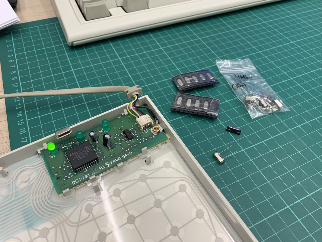
I managed to fix my M2!
It was the corroded crystal that caused my board to fail.
I tried to replace it with a generic 4Mhz SMD crystal but it was to wide for the board.
I could have bodged it but ended up using a though hole crystal standing on top of the board with bent legs instead.
Hope this is helpful for anyone passing through here with the same problem.
PS. The caps are still the most common problem with the M2.
Replace the caps first. In this case the electrolyte from the leaky caps probably killed my original crystal.