Mounting holes: any opinions on the "semi-breakaway ears", like here?
@Mohit: By all means, please try to route the thing with holes. It should be doable with the extra 2mm in height, I had most trouble with the pins where the MCU was too close. I went with OSH Park's design rules (which are pretty much the same also with the Chinese fabs I used). The schematic is correct (by which I mean I used essentially the same schematic for my already existing KL27Z breakout).
Can we design the teensy alternative for keyboards?
-
flabbergast

- Location: Southampton, UK
- DT Pro Member: 0120
- Contact:
About haata's firmware: it would need a small update (different MCU initialisation and EEPROM emulation), but this is a one-off thing; all the drivers (USB, I2C, GPIO) are the same on this chip as on the Infinity/WhiteFox/Teensy3.
-
mohitgarg
- Main mouse: R.A.T 7
- Favorite switch: Blue
- DT Pro Member: -
A little OT but have you checked out Easy AVR? Do you think it might possible to port it for ARM devices?flabbergast wrote: ↑About haata's firmware: it would need a small update (different MCU initialisation and EEPROM emulation), but this is a one-off thing; all the drivers (USB, I2C, GPIO) are the same on this chip as on the Infinity/WhiteFox/Teensy3.
-
matt3o

- -[°_°]-
- Location: Italy
- Main keyboard: WhiteFox
- Main mouse: Anywhere MX
- Favorite switch: Anything, really
- DT Pro Member: 0030
- Contact:
okay then. ARM it is! It seems a future proof choice and it gives us more room for future improvements.
Regarding size, I agree the USB should stick at least 2mm but we don't have 22mm vertically.
But I don't want to make things too expensive nor complicated. If we can fit everything with standard pad holes, let's do it.
Regarding size, I agree the USB should stick at least 2mm but we don't have 22mm vertically.
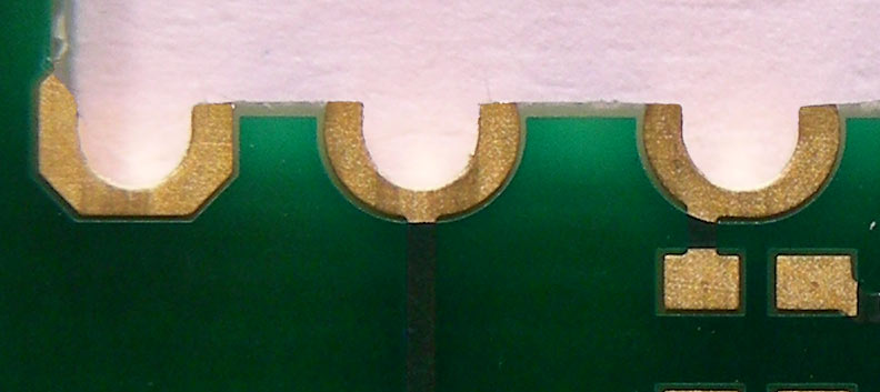
I wouldn't go 1.27mm unless we really have to. To get few mm back we could use half-holes maybe? That would also let solder the daughter board directly on the PCBflabbergast wrote: ↑ - 1.27mm headers are an option, but IMO they're way more fiddly to solder wires to than the standard ones
not sure I follow here. why would you do that? don't we just need a ribbon cable with the right connector at the end? We could provide that with say 30cm cable that you could cut based on your needs.flabbergast wrote: ↑ - various flat PCB connectors: this would be probably nice, but we would need to also make another PCB for "flat connector to 2.54mm pads" for the hand-wiring option
But I don't want to make things too expensive nor complicated. If we can fit everything with standard pad holes, let's do it.
oooh this is nice! I mean this is just 30mm right? Plenty of room to add screw holes!flabbergast wrote: ↑{Also another pic now with pointy corners and a better USB footprint (from Mohit). EDIT: The dimensions are still more-less the same, 18.3mm including the peninsula.}
-
matt3o
- -[°_°]-
- Location: Italy
- Main keyboard: WhiteFox
- Main mouse: Anywhere MX
- Favorite switch: Anything, really
- DT Pro Member: 0030
- Contact:
-
flabbergast
- Location: Southampton, UK
- DT Pro Member: 0120
- Contact:
Well I meant that hand-wiring version wouldn't have to solder to the ribbon cable coming out of the connector directly. But that's of course possible, and it's definitely cheaper than having another board as an intermediary.matt3o wrote: ↑not sure I follow here. why would you do that? don't we just need a ribbon cable with the right connector at the end? We could provide that with say 30cm cable that you could cut based on your needs.flabbergast wrote: ↑ - various flat PCB connectors: this would be probably nice, but we would need to also make another PCB for "flat connector to 2.54mm pads" for the hand-wiring option
It's 31.3mm width now.matt3o wrote: ↑ oooh this is nice! I mean this is just 30mm right? Plenty of room to add screw holes!
That's of course not a problem; one counterpoint is that with the board this small, you can't fit all the pads around the PCB edge (I mean not with 2.54mm pitch), so some of the pads will necessarily remain inside the board. Also you might want to check with your supplier if they can do this - some fabs (like OSH Park) require some separation between the copper and the PCB edge.matt3o wrote: ↑ To get few mm back we could use half-holes maybe? That would also let solder the daughter board directly on the PCB
-
matt3o
- -[°_°]-
- Location: Italy
- Main keyboard: WhiteFox
- Main mouse: Anywhere MX
- Favorite switch: Anything, really
- DT Pro Member: 0030
- Contact:
you could probably add one column of pads to the left and right and sacrifice a couple of holes in the middle for the screws and still stay under the specificsflabbergast wrote: ↑It's 31.3mm width now.
-
vvp

- Main keyboard: Katy/K84CS
- Main mouse: symetric 5-buttons + wheel
- Favorite switch: Cherry MX
- DT Pro Member: -
1.27 mm pins are better than a board to wire connector. One at least has a chance to buy standard 2.54 or 1.27 pin headers in small quantities, corresponding IDC/IDT connectors for them and the flat ribbon cables. So it should be either 2.54 or 1.27 pin headers or a mix of them. 2.54 is preferable if it fits.
Why insist on screw holes. One can scarify four ports of the microcontroller. Use a file to create indentations on four 1x1 2.45 pins. Solder the pins to the PCB. Glue the sticking out pins into corresponding holes in the case. The point is as soon as you go with smaller than Ø 3 mm screws then it is hard to buy them is common hardware shops anyway. One needs to go to RC-model shops to get so small screws. RC-model shops are much more sparse.
Why insist on screw holes. One can scarify four ports of the microcontroller. Use a file to create indentations on four 1x1 2.45 pins. Solder the pins to the PCB. Glue the sticking out pins into corresponding holes in the case. The point is as soon as you go with smaller than Ø 3 mm screws then it is hard to buy them is common hardware shops anyway. One needs to go to RC-model shops to get so small screws. RC-model shops are much more sparse.
-
matt3o
- -[°_°]-
- Location: Italy
- Main keyboard: WhiteFox
- Main mouse: Anywhere MX
- Favorite switch: Anything, really
- DT Pro Member: 0030
- Contact:
that might work, but if we can do it with bigger pins within specifics, why bother?vvp wrote: ↑1.27 mm pins are better than a board to wire connector. One at least has a chance to buy standard 2.54 or 1.27 pin headers in small quantities
M2.5 are pretty common and can be easily found on ebay (a quick search returned 25396 results, M2 38556 results), availability is not an issue, we could even provide a couple of screws, I don't think that would impact on pricing too much.vvp wrote: ↑Why insist on screw holes.
This board is all about options. If you want to glue it, you are free to do so. Do you want to route the USB with an extension cable? Go ahead! You want to use the onboard USB directly? Sure, no problem!
I've built a dozen hard-wired keyboars by now and I would always have appreciated the option to screw the teensy somewhere.
-
Matt_
- Location: France
- Main keyboard: KBT Pure Pro
- Main mouse: G500
- Favorite switch: MX Red, MX Blue
- DT Pro Member: -
I love the connector + ribbon idea. Female connector on the controller board, male connector on one end of the ribbon, loose wires on the other side:
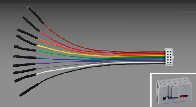
So that we can solder the loose wires either to pads on the keyboard PCB (which means pcb designers won't have to bunch up pads to mimic the controller disposition and use headers), or to the matrix rows and columns in the case of a hand-wired keyboard. Like this (think controller on the right, keyboard PCB on the left):

Solderability should not be an issue, unless you want a connector on both ends, but I can't see in which case it should be desirable — the ability to disconnect the ribbon on the controller's side should be enough. And if we don't need to solder a connectors ourselves, we can use 1.27mm pitch to save space if needed. But we would have to make sure that it's easy to buy spare ribbon cables with the right connector so that we won't have to work with a crimping tool to make the cable.
So that we can solder the loose wires either to pads on the keyboard PCB (which means pcb designers won't have to bunch up pads to mimic the controller disposition and use headers), or to the matrix rows and columns in the case of a hand-wired keyboard. Like this (think controller on the right, keyboard PCB on the left):
Solderability should not be an issue, unless you want a connector on both ends, but I can't see in which case it should be desirable — the ability to disconnect the ribbon on the controller's side should be enough. And if we don't need to solder a connectors ourselves, we can use 1.27mm pitch to save space if needed. But we would have to make sure that it's easy to buy spare ribbon cables with the right connector so that we won't have to work with a crimping tool to make the cable.
-
matt3o
- -[°_°]-
- Location: Italy
- Main keyboard: WhiteFox
- Main mouse: Anywhere MX
- Favorite switch: Anything, really
- DT Pro Member: 0030
- Contact:
I like the header thing too. The header has to be super flat though and parallel to the PCB (not vertical like in Matt_'s picture), we would have to find the right one and provide with the companion ribbon hoping the price is not too bad. As I said I don't want to make things too complicated.
-
vvp
- Main keyboard: Katy/K84CS
- Main mouse: symetric 5-buttons + wheel
- Favorite switch: Cherry MX
- DT Pro Member: -
If you use standard 2.54 or 1.27 pin headers then you can buy IDC/IDT connectors for them in small quantities. These are common in the price range of about 1-2 €. Depends on pin count, some pin counts are more common and therefore cheaper, some are rare and much more expensive (if available at all). You can mount the connector on a ribbon cable using a small vise (if you do not have the proper crimp tool).
-
Matt_
- Location: France
- Main keyboard: KBT Pure Pro
- Main mouse: G500
- Favorite switch: MX Red, MX Blue
- DT Pro Member: -
Let's say that it would be a nice bonus, but not a primary requisite 
And yeah, we would need a flat-ish connector on the controller in order not to make it unnecessarily thick. I'll scour mouser's catalog later to see if I can find something suitable.
And yeah, we would need a flat-ish connector on the controller in order not to make it unnecessarily thick. I'll scour mouser's catalog later to see if I can find something suitable.
-
derzemel

- Location: Bucharest, Romania
- Main keyboard: FC660C, SSK, TX-1800 Nixie
- Main mouse: Mionix Naos 7000
- Favorite switch: Alps SKCL/SKCM tactile
I was just thinking at the Molex Pico-Lock connector:mohitgarg wrote: ↑There are solutions from Molex, but then again pricing isn't too encouraging, about $2 for the connector at 100+ and $10+ for cables.

-
mohitgarg
- Main mouse: R.A.T 7
- Favorite switch: Blue
- DT Pro Member: -
I was thinking these, http://www.molex.com/molex/products/fam ... connectors
-
matt3o
- -[°_°]-
- Location: Italy
- Main keyboard: WhiteFox
- Main mouse: Anywhere MX
- Favorite switch: Anything, really
- DT Pro Member: 0030
- Contact:
if pricing is really like that, forget about itmohitgarg wrote: ↑There are solutions from Molex, but then again pricing isn't too encouraging, about $2 for the connector at 100+ and $10+ for cables.
-
mohitgarg
- Main mouse: R.A.T 7
- Favorite switch: Blue
- DT Pro Member: -
-
flabbergast
- Location: Southampton, UK
- DT Pro Member: 0120
- Contact:
The molex pico-lock looks cute. Don't know whether they make them with sufficiently many pins; we can do more than one connector, but that would up the price.
BTW, I am not categorically against 1.27mm headers, but they should be designed to have a connector to be soldered there - they are really a pain to solder wires to. Definitely not beginner-DYI-friendly.
BTW, I am not categorically against 1.27mm headers, but they should be designed to have a connector to be soldered there - they are really a pain to solder wires to. Definitely not beginner-DYI-friendly.
-
flabbergast
- Location: Southampton, UK
- DT Pro Member: 0120
- Contact:
I've just discovered flexible flat cables (FFC) (e.g. this or this, connector like this). Does anyone have any experience with cutting that kind of cable and soldering to the wires directly - i.e. is it similar to cutting a "normal" ribbon cable?
EDIT: googling ... it doesn't look like a good idea, certainly not for hand-wiring. My favourite option at the moment is to stick with the traditional pads, at most have half-pads on the sides of the board, and just invest the time on routing the thing properly.
EDIT: googling ... it doesn't look like a good idea, certainly not for hand-wiring. My favourite option at the moment is to stick with the traditional pads, at most have half-pads on the sides of the board, and just invest the time on routing the thing properly.
-
Matt_
- Location: France
- Main keyboard: KBT Pure Pro
- Main mouse: G500
- Favorite switch: MX Red, MX Blue
- DT Pro Member: -
Agreed, the whole idea seems less appealing after a few searches. It's probably better to not clutter the project with costly and unneeded features and stick to the original plan with regular pads on the board.
Has a choice been made between AVR and ARM? The former boasts bigger compatibility with existing firmwares and Arduino, the latter is probably less expensive and more future-proof. If the project gains traction in the keyboard community, we may well see more code ported to or designed for ARM anyway, so why not go for it?
Has a choice been made between AVR and ARM? The former boasts bigger compatibility with existing firmwares and Arduino, the latter is probably less expensive and more future-proof. If the project gains traction in the keyboard community, we may well see more code ported to or designed for ARM anyway, so why not go for it?
-
matt3o
- -[°_°]-
- Location: Italy
- Main keyboard: WhiteFox
- Main mouse: Anywhere MX
- Favorite switch: Anything, really
- DT Pro Member: 0030
- Contact:
yeah we are pretty much settled on ARM at this point.
I would stick with the traditional pads too. half-pads are an option but not terribly needed. I kinda like the idea of having both holes and castellated pcb though (like the espruino) Of course only for external pads.
I would stick with the traditional pads too. half-pads are an option but not terribly needed. I kinda like the idea of having both holes and castellated pcb though (like the espruino) Of course only for external pads.
-
flabbergast
- Location: Southampton, UK
- DT Pro Member: 0120
- Contact:
OK, another try. Having more space really made the routing pretty simple. Pic here. This one has one less pad (so only 29 potentially usable pins), and it's a bit bigger: 18.67mm x 33.02mm, the peninsula included. The peninsula itself is 2.4mm tall though.
Two mounting holes, each 2.3mm dia, clearance dia 4mm (I mean there are no components or tracks in a disk with 2mm radius about the center of the hole) - this should be enough for M2 screws.
Two mounting holes, each 2.3mm dia, clearance dia 4mm (I mean there are no components or tracks in a disk with 2mm radius about the center of the hole) - this should be enough for M2 screws.
-
matt3o
- -[°_°]-
- Location: Italy
- Main keyboard: WhiteFox
- Main mouse: Anywhere MX
- Favorite switch: Anything, really
- DT Pro Member: 0030
- Contact:
that looks totally fine to me. Are you comfortable with 29 i/o?
-
flabbergast
- Location: Southampton, UK
- DT Pro Member: 0120
- Contact:
I personally am fine with that, that should be just enough for a TKL (24) plus 3 LEDs plus 2 pins for an extra chip (e.g. either backlight or wireless) or hardware debugging.
If the general consensus will be that more-less this layout is fine, @Mohit should probably have a go at it as well to improve the routing, footprint placement and silkscreen
BTW lots of the pins have PWM (the thing to look for in the datasheet is that one of the alternative functions is a timer output, denoted TPM* in the pinout table in the datasheet). Also it is possible to repurpose the reset button in the firmware to make that pin to behave just like any other GPIO pin, which would make the 30th pin to be also usable for something else. Of course then the only way to reset the board would be to replug.
Finally I've just found out on the web that someone wanted to make a chrome plugin that could flash the chip directly from the browser (supposed to be possible using chrome HID api and the fact that the bootloader on this thing is also HID). I don't think he finished the project, so at this moment it's just a possibility (which is way out of my comfort zone, so I can't tell if it's possible or not).