
I can't wait to get my hands on mine!
Regarding the USB connection, maybe a solution like the one Phosphorglow used on his Universal M Controller would be good?
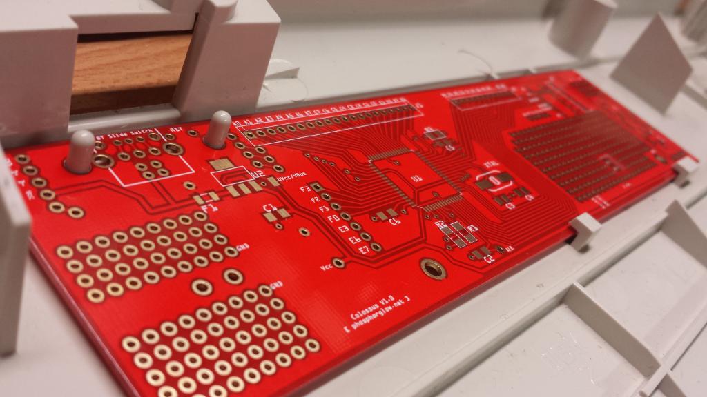
Essentially a small breakout board, with USB B connector and holes spaced correctly for the pins on the SSK case.
Phosphorglow uses nylon risers slit along their length as clamps to hold the PCB down.
post219719.html#p219719
Also, regarding mixing flippers, on my AT I have a couple of XT flippers with absolutely no issues.


