lot_lizard wrote: ↑
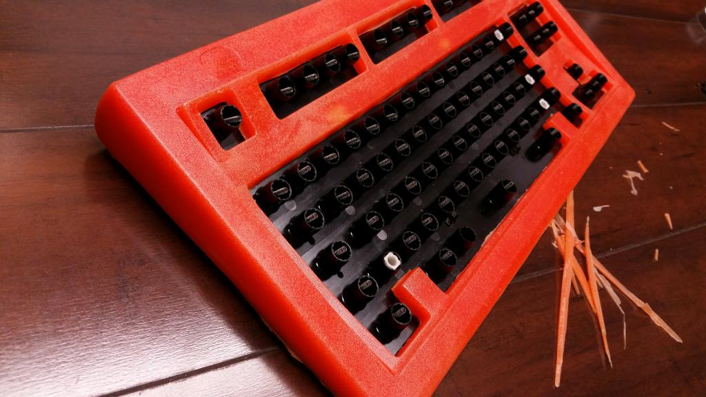
Thanks for the tip. I'll order some and try it. The big thing would be durability, and it seems to have properties very similar to ABS on that end (impact resistance with some flex). We will be screwing into the stabilizer clips from underneath, so we need it to secure well with sheet metal screws without worrying about cracking them (not exact dimensions, but example below).
PETG is far superior than ABS when it comes to bonds between the layers.
ABS just sticks to itself along the layer where PETG forms a chemical bond with the layer below , far stronger in that regard.
PETG has to be good quality and has to be kept dry , even more so than other filaments, if it gets damp and then is melted as the water molecule fucks with the polymer string and makes it brittle.
So stick with good quality brands at least for PETG, so go with the edge, they should sell it in evil ultimaker size as well.
Good brands for ABS and PLA are verbatim and esun respectively
I prefer verbatim as it works at more normal ABS temps, esun i have never used but it is supposed to be good however its ABS is a bit strange and prints at a lower temp, nothing wrong with that but it puts me off its PLA however is fantastic.
Off topic 3D printer talk.
I was servicing our Up Plus2 printers in work today as they have been used and abused for years. The amount 3D printers have moved on since 2013 is amazing! I mean the Up was not a cheap printer when it was new , hell it still sells for over 700 GBP and it has 3d printed parts in it! Its build area is tiny and its bed is held on by little metal clips that do nothing.
The Z axis guide on one of them has broken as its only a 3D printed item with a bearing pressed into it.
Its extruder is pathetic, its a tiny little plastic part ( injection molded ) that clips over the NEMA17 stepper no spring tensioner or anything.
The hot end however is the absolute dogs(that means good)! Its an all metal hot end , its super small super rugged, it can reach 300c without breaking a sweat in less than 2 mins, is the best thing about the printer hands down! They still use exactly the same hot end now on the brand new Up Box. Awesome!
But compare that to say , the Wanhao 6 , that thing has the all new MK11 extruder and hot end, has an enclosed build chamber and its all metal , not a single 3d printed part on it.