I didn't add any jumpers on the left hand side pcb. where should the go?dox wrote:Did you place the jumpers correctly on the side of the TRRS connector? Any photo of your PCBs?
Split ergonomic keyboard project
-
litster

- Location: Washington State, USA
- Main keyboard: KMAC2, The Cheat
- Favorite switch: Brown, Topre, Red, BS
- DT Pro Member: -

-
Ian S
- Location: UK
- Main keyboard: QPAD MK85 MX-Reds
- Main mouse: Logitech MX Revolution
- Favorite switch: MX-Red at moment
- DT Pro Member: -
Thanks four your response 
I remembered another question I had. Some of the current crop of nkey rollover over USB boards seem to have a problem with ignoring a key press or endlessly repeating a character. Is this ErgoDox an nkey rollover over USB and will it be without that issue?
Do you mean the number row above the qwerty row? That won't do it, hence the number pad, especially with it's /*-+=.ic07 wrote:the integrated number pad on the ErgoDOX.
I'm subscribed to this thread now.ic07 wrote:Check back periodically
Do you mean affixing a USB socket to the left hand to make it easier to join to a left hand situated number pad? I've never tried to use a PC number pad with the left had, only the telephone, I think I use the right one on there too out of familiarity more than handedness. But I've noticed that the left is sometimes the favoured place, so the mouse can go on the right.ic07 wrote:Doing things differently
If they do, it would be nice if they share it with us all in this threadic07 wrote:Somebody mentioned that they were going to make theirs wireless.
I wonder if one of those Logitech K750, bought cheaply, could be taken apart and it's solar power parts spliced to an ErgoDox.ic07 wrote:batteries
I remembered another question I had. Some of the current crop of nkey rollover over USB boards seem to have a problem with ignoring a key press or endlessly repeating a character. Is this ErgoDox an nkey rollover over USB and will it be without that issue?
-
ic07
- DT Pro Member: -
:)
Oh no no no... The keyboard will support layers, so it's possible to have a conventional number pad embedded however you like - possibly activated by a numlock key, as it's done in some laptop keyboards (except that the ergodox has non-staggered columns, so it should be a little less awkward to use). The current implementation of a QWERTY layout, for example, has an embedded number pad on the third layer, which is activated when you engage numlock. I still need to debug the functionality a little bit though...Ian S wrote:Do you mean the number row above the qwerty row?
That would require a bit of a hardware/firmware mod, yes.Ian S wrote:Do you mean affixing a USB socket to the left hand ...
The keyboard isn't N-KRO right now, only 6-KRO, and I've never seen/heard of any problems of that sort. I may have time to make it N-KRO in the future though. But, you're asking the developer (me) if the firmware's going to have bugs.. lol. I'm doing my best :) .Ian S wrote:I remembered another question I had. Some of the current crop of nkey rollover over USB boards seem to have a problem with ignoring a key press or endlessly repeating a character. Is this ErgoDox an nkey rollover over USB and will it be without that issue?
-
Ian S
- Location: UK
- Main keyboard: QPAD MK85 MX-Reds
- Main mouse: Logitech MX Revolution
- Favorite switch: MX-Red at moment
- DT Pro Member: -
I see, well that might be workable for me, but I'd have to give it a go. That's my plan with this really, just try it and see how I get on. Been with the 'normal' keyboard layout for over 30 years so it might take a bit of time to adjust even if it's to something betteric07 wrote:The keyboard will support layers, so it's possible to have a conventional number pad embedded however you like
I expect that should do it?? I never press more than about three keys anyway.ic07 wrote:The keyboard isn't N-KRO right now, only 6-KRO
I just had another idea that other people probably had many pages earlier. As the pads are likely to be rotated at an angle to the user, it would be nice if the letters on the key caps were at the opposite angle so they appear straight.
Would the normal cherry shape key caps work better than round caps with this design as the keys are aligned? I quite like the subtly concave round caps on the Logitech K750 board. They seemed to help me reduce a vertical error in finger placement by directing the tips to the cap centres.
Thanks
-
litster
- Location: Washington State, USA
- Main keyboard: KMAC2, The Cheat
- Favorite switch: Brown, Topre, Red, BS
- DT Pro Member: -
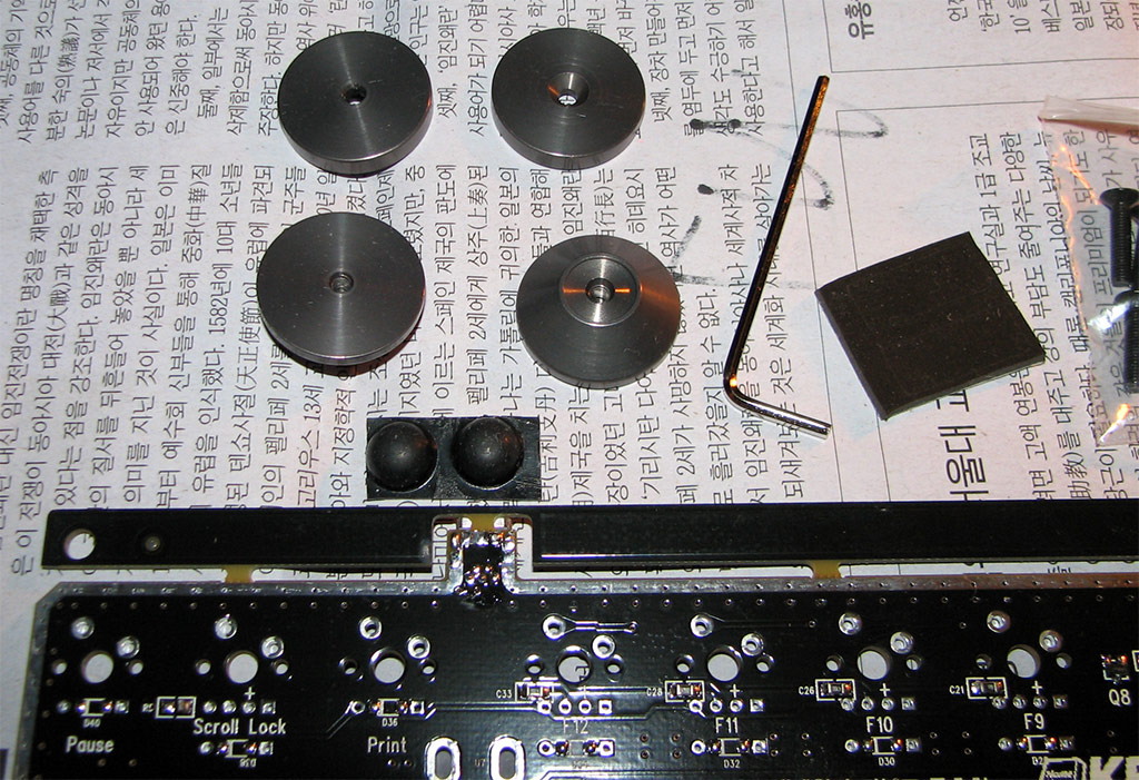
Yes! it is working after I connected the 4 missing bridges.
Now I need to desolder all though-hole diodes and solder SMD diodes on the back of the PCBs so I can use a thick acrylic plate
Now I need to desolder all though-hole diodes and solder SMD diodes on the back of the PCBs so I can use a thick acrylic plate
-
ic07
- DT Pro Member: -
@Ian S:
Last I heard, keycaps (and switches) were buy-it-yourself parts (unless of course someone's assembling it for you) - which means, you can get any kind of caps with any kind of lettering you can find . I've never seen rotated lettering, but then, I haven't looked very hard... (my keycaps are blank right now).
@litster:
Awesome! And lol... have fun.
Last I heard, keycaps (and switches) were buy-it-yourself parts (unless of course someone's assembling it for you) - which means, you can get any kind of caps with any kind of lettering you can find
@litster:
Awesome! And lol... have fun.
-
judascleric
- Main keyboard: TrulyErgonomic 209
- Main mouse: MacBook Pro Trackpad(only when keyboard can't)
- Favorite switch: Cherry MX Brown
- DT Pro Member: -
ErgoDox is an awesome project. I found it after getting a TrulyErgonomic and being inspired to design my own keyboard and ending up on DT searching for design and hardware reference. It's exciting to see it coming so far along. Put me down for PCBs and a case when the group buy comes along.
I was going over the parts list on ErgoDox.org and noted the omission of keycaps. I'm new to this scene and ordering keycaps is a bit of baffling process to me, especially in regards to the ergodox project where you can't just pick up a standard 87 or 104 key set. I just want basic blank stock caps! Maybe other people are in the same boat? Maybe the hardware part list could suggest an website for ordering a set of blank, black caps with quantities/sizes/row profiles for the whole board as a starting point for people who aren't too picky about caps?
Barring this addition, I have a few questions to help me work through my own part list for caps:
Does it make sense to order a standard 87 key set and supplement the extra 1.5x1 keys (seems like the approach for wasdkeyboards.com) or order an entire custom 76-key set (seems like the approach for solutionsinplastic.com)?
What row profiles would you use for the vertical middle 1.5x1 sized keys?
What row profiles would you use for the thumb cluster 1x1 and 2x1 keys?
Are there any stabilizer springs planned on any of the non-1x1 keys? (ic07's latest pics show some extra holes on the PCB that suggest this may be the case) If so, how does that play into ordering non-1x1 keys?
Here is my best guess for a keycap list with my current understanding:
Keycap row/size list:
Row 1 - Main keys - 10x(1x1), Pinky outer column - 2x(1.5x1), Index finger inside column - 2x(1x1), Thumb Cluster - 4x(1x1)
Row 2 - Main keys - 10x(1x1), Pinky outer column - 2x(1.5x1), Index finger inside column - 2x(1.5x1), Thumb Cluster - 2x(1x1)
Row 3 - Main keys - 10x(1x1), Pinky outer column - 2x(1.5x1), Index finger inside column - 2x(1.5x1), Thumb Cluster - 2x(1x1), Thumb Cluster - 4x(2x1)
Row 4 - Main keys - 10x(1x1), Pinky outer column - 2x(1.5x1)
Row 5 - Main keys - 10x(1x1)
-
ic07
- DT Pro Member: -
The extra holes on the PCB are for optionally using two 1x keys in the place of each 2x thumb key. On the first prototype Dox had stabilizer slots in the plate he was using, so I imagine there'll be a plate available when the group buy happens with the same sort of thing. I dunno for sure if it's possible to use PCB mounted stabilizers with the current design or not, but I kinda think not... On the other hand (if for some reason you prefer not to use plate mounted things) the 2x keys aren't all that bad without stabilizers, actually. But you may want to get the opinion of someone who's more picky as to the tradeoffs there.
You sound like you're going for sculpted caps, so this might not help much, but: my keycaps are all standard DCS Row 2 from solutionsinplastic. All the caps are rotated so that they slope with the low side toward the home row, with the home row having the low side on the top. The 1.5x and 2x keys are sloped inward as well (with the inside of the key being low). The 1x keys in the thumb group all have the low side on the bottom - which isn't ideal I guess, but I didn't find a better configuration.
There are many ways to do it, and I'm not sure mine's the best (or the cheapest..).. but it's fairly simple and I like it, and it's my first build, so.. :)
-
bisl
- Main keyboard: Filco Majestouch-2 TKL Red
- Main mouse: SteelSeries Sensei (left) Xai (right)
- Favorite switch: Cherry MX Red
- DT Pro Member: -
Actually, on that note--what's currently standing between the current state of progress and the group buy? I know the GUI isn't done, but reading through litster's beta testing it seems like the parts are capable. I can't speak for everyone, but I would guess that most of the people interested in ErgoDox wouldn't mind waiting for the GUI with keyboard in-hand, if the design isn't going to change again. Not to mention it would be indulging all of our (my) obsession over this project.ic07 wrote:when the group buy happens
With that said: are there adjustments that need to be made to the PCBs before they're produced? As well, the case designs have been up on ergodox.org for a while; are these not actionable yet? Do group buy logistics just need to be figured out and organized?
-
dorkvader

- Main keyboard: Unicomp
- Main mouse: CST 1550
- Favorite switch: Buckling Spring over Capacitave. (Model F)
- DT Pro Member: -
The Case/plate design still needs to be updated reflecting the change in the PCB (Moving the thumb-area inwards a bit). Once this is done, we can, in theory, start getting quotes from a machine shop. I also need to look over it, and see if it's possible to have the screw holes get wider, for those conical screw heads to fit, and be almost flush. Ideally, we'd have hexagonal holes on the other side of the "layer-cake" for nuts to fit flush. If we alternate which side the bots fit on, we don't need threaded holes through the really thin layers, and it'd still fit flush.
Unfortunately, I don't know enough CAD to work this out.
JesusWasAZombie at GH wants to organize an electronic parts GB, I have no problem organizing, sorting, buying, etc. as well. We'd also need a purchase plan for keycaps (possible GB? I'm sure we can work something out with WASDkeyboards or signature plastics for a ton of blanks) and possibly keyswitches. I mean, mouser carries lots keyswitches. You can sometimes get some on verical at good rates, and WASDkeyboards isn't bad.
Doesn't the PCB need to be updated to give VCC to the I2C or something? I'm not really up-to-date on that, and I'm not really good on how I2C (I^2C?) works.
Also, on that note, I've updated the interest list to the best of my knowledge. If you're not on it, PM me here or on GH. I'm on GH more, so if you've an account there, I'll be able to get back to you faster.
-
dox
- Main keyboard: doxKB
- Main mouse: G700
- Favorite switch: ergo clear
- DT Pro Member: -
I'm almost done on the plate laminate case design. I just need a few extra hours to finish it.
I've been very busy in the past weeks. I bought my first house and I'm moving in saturday.
Countersunk screws would be nice and possible but they require extra machining after the cutting and I would like to avoid that to keep the price as low as possible.
Edit: The PCB doesn't absolutely need to be revised. The only "problem" is that if you want to plug the usb cable directly in the teensy instead of the extra usb connector, you have to add a wire between the vcc on the teensy and the usb vcc pad.
I've been very busy in the past weeks. I bought my first house and I'm moving in saturday.
- plateDesign1.PNG (175.97 KiB) Viewed 9551 times
- plateDesign2.PNG (89.21 KiB) Viewed 9551 times
Edit: The PCB doesn't absolutely need to be revised. The only "problem" is that if you want to plug the usb cable directly in the teensy instead of the extra usb connector, you have to add a wire between the vcc on the teensy and the usb vcc pad.
-
litster
- Location: Washington State, USA
- Main keyboard: KMAC2, The Cheat
- Favorite switch: Brown, Topre, Red, BS
- DT Pro Member: -
Dox, I am also drawing an acrylic case at the moment, and I hope to do a test cut tonight. It will have an acrylic plate. Due to the thumb cluster area, I am not sure where I can place the feet to still make it stable.
Where are you putting the feet?
Where are you putting the feet?
-
dox
- Main keyboard: doxKB
- Main mouse: G700
- Favorite switch: ergo clear
- DT Pro Member: -
Great!
For the feet, it depends on how you want to have it sloped or flat. To get a slope, I would place the 3 corners first and try to mark the position of the thumb foot before sticking it. Or with the dimensions of the feet I could determine the exact position from my 3D model.
For the feet, it depends on how you want to have it sloped or flat. To get a slope, I would place the 3 corners first and try to mark the position of the thumb foot before sticking it. Or with the dimensions of the feet I could determine the exact position from my 3D model.
-
litster
- Location: Washington State, USA
- Main keyboard: KMAC2, The Cheat
- Favorite switch: Brown, Topre, Red, BS
- DT Pro Member: -
I am thinking potentially use the same aluminum feet I have from my KMAC and MX Mini, 3 on each side at (top left, top right, and lower left - for the right hand). These feet are about 2cm tall with rubber feet. And then I would use a small rubber feet for the lower right corner. So the 3 yellow circles would be the high points and slope down to the lower right corner.
- ergodox bottom.png (10.9 KiB) Viewed 9534 times
-
dox
- Main keyboard: doxKB
- Main mouse: G700
- Favorite switch: ergo clear
- DT Pro Member: -
One of the 3 feet (upper left) from the KMAC need to be taller then the other 2 to have the slope that you want. This is the slope I'm using at work with my 2nd shapeways case (I need to post pics of that) and it's very comfortable.
-
webwit

- Wild Duck
- Location: The Netherlands
- Main keyboard: Model F62
- Favorite switch: IBM beam spring
- DT Pro Member: 0000
- Contact:
Kmac height options, for reference:
Well it's actually not very clear from the picture. And those black titties are rubbers are for under the feet.
Well it's actually not very clear from the picture. And those black titties are rubbers are for under the feet.
-
Vierax

- Location: France (Lille)
- Main keyboard: Tipro MID KM128 Bépo layout
- Main mouse: Kensington Orbit Trackball
- Favorite switch: MX Clear / MX Grey (under thumbs)
- DT Pro Member: -
- Contact:
No way ! How can you create a great splitted bear-pawed keyboard with thumb keys and not make a M$ Natural Keyboard's inclination ? Those feet are in the wrong way, they don't let hands in their natural falling down. Ergonomically speaking, it'd better to let the board in a flat way on the desk rather than mounting those feet.litster wrote:I am thinking potentially use the same aluminum feet I have from my KMAC and MX Mini, 3 on each side at (top left, top right, and lower left - for the right hand). These feet are about 2cm tall with rubber feet. And then I would use a small rubber feet for the lower right corner. So the 3 yellow circles would be the high points and slope down to the lower right corner.
Sorry bros, that's a very bad idea.
-
webwit
- Wild Duck
- Location: The Netherlands
- Main keyboard: Model F62
- Favorite switch: IBM beam spring
- DT Pro Member: 0000
- Contact:
There is some truth to that. They are very good looking, but not very adjustable. I'd expect to see these on old audio equipment. What can be said in favor is that anyone can get their preferred size as long as the screw size fits.
-
dox
- Main keyboard: doxKB
- Main mouse: G700
- Favorite switch: ergo clear
- DT Pro Member: -
With alu plates, you can drill/tap some holes in the bottom plate and get any slope by fitting different screws in those holes.
I tried a lot of different configurations and the best for me is a slope from the inner top to the outer bottom.
I tried a lot of different configurations and the best for me is a slope from the inner top to the outer bottom.
-
Vierax
- Location: France (Lille)
- Main keyboard: Tipro MID KM128 Bépo layout
- Main mouse: Kensington Orbit Trackball
- Favorite switch: MX Clear / MX Grey (under thumbs)
- DT Pro Member: -
- Contact:
We're agreed that the slope shoud be from the inner to the outter, not for the top/bottom partdox wrote: I tried a lot of different configurations and the best for me is a slope from the inner top to the outer bottom.
To avoid misunderstanding : you talk about this slope ↙ ↘ , arrows from the high point to the low, and I talk about that ↖ ↗
-
litster
- Location: Washington State, USA
- Main keyboard: KMAC2, The Cheat
- Favorite switch: Brown, Topre, Red, BS
- DT Pro Member: -
Here it is. A couple of mistakes like the 3.5mm opening is too narrow, forgot the make room for the USB connector on the layers that sandwich the acrylic plate. I want to have a built-in wrist rest to the case as well. I will have to make all those changes for the next prototype.

Top view:

BTW, to use this case, you will need to solder SMD diodes or through-hole diodes on the bottom of the PCB. SMD diodes on the bottom is better as you would not need to worry about the diode legs sticking up from the bottom.
Top view:
BTW, to use this case, you will need to solder SMD diodes or through-hole diodes on the bottom of the PCB. SMD diodes on the bottom is better as you would not need to worry about the diode legs sticking up from the bottom.
-
planet36
- Location: USA
- Main keyboard: MS Natural 4000
- Main mouse: Evoluent vertical mouse
- Favorite switch: Cherry MX Red
- DT Pro Member: -
- Contact:
Looks beautiful! I'm really stoked about this keyboard.litster wrote:Here it is. A couple of mistakes like the 3.5mm opening is too narrow, forgot the make room for the USB connector on the layers that sandwich the acrylic plate. I want to have a built-in wrist rest to the case as well. I will have to make all those changes for the next prototype.
Top view:
BTW, to use this case, you will need to solder SMD diodes or through-hole diodes on the bottom of the PCB. SMD diodes on the bottom is better as you would not need to worry about the diode legs sticking up from the bottom.
-
Vierax
- Location: France (Lille)
- Main keyboard: Tipro MID KM128 Bépo layout
- Main mouse: Kensington Orbit Trackball
- Favorite switch: MX Clear / MX Grey (under thumbs)
- DT Pro Member: -
- Contact:
wow ! that's great
I like this transparency case, everything should be like this (except clothes and walls : I'm strangely attached to privacy and intimacy )
)
I like this transparency case, everything should be like this (except clothes and walls : I'm strangely attached to privacy and intimacy


-
pingbat
- Location: Germany
- Main keyboard: Das U
- Main mouse: Steelseries Sensei
- Favorite switch: Cherry Blue
- DT Pro Member: -
I was just thinking, the case design might present a chance for some cool DT keyrings or something. Maybe even a stand to raise the back of the keyboard? Unless there are plans for the cut out material already.