Cortron (ITW) 55-500216

MMcM

10 Aug 2020, 05:36

This Cortron keyboard was part of a CPT 8000 series word processor from the end of 1979.
CPT-case-black.jpg
CPT-case-black.jpg (368.82 KiB) Viewed 4360 times
It is more than 2 ft. long. The case is steel, so the whole weighs 9.5 lbs.

It has full-height magnetic valve switches. The key caps were pretty dirty, but the switches themselves are still quite smooth after forty years. Most caps are double-shot, except, for some reason, the MOVE key; perhaps it was a replacement.
Cortron-55-500215.jpg
Cortron-55-500215.jpg (426.77 KiB) Viewed 4360 times
The PCB, 80-551646, is rev A.
Cortron-80-551646-rev-A.jpg
Cortron-80-551646-rev-A.jpg (470.74 KiB) Viewed 4360 times
The later CPT 8500 used rev C. XMIT got one of them from elecplus a few years ago (scroll down to second from the end). That one has beige keys but otherwise the same layout, except fewer blank keys, which might be replacements here. It also has a beige case, 1.5 inches shorter and made of aluminum. So it weighs maybe half as much. It did, no doubt, look a lot more professional in an office, though. I have a line on one of those and suspect that this conversion effort will work for it, too.

Some of the noticeable things about the keyboard layout and legends may mostly be that it came from an early dedicated word processor.
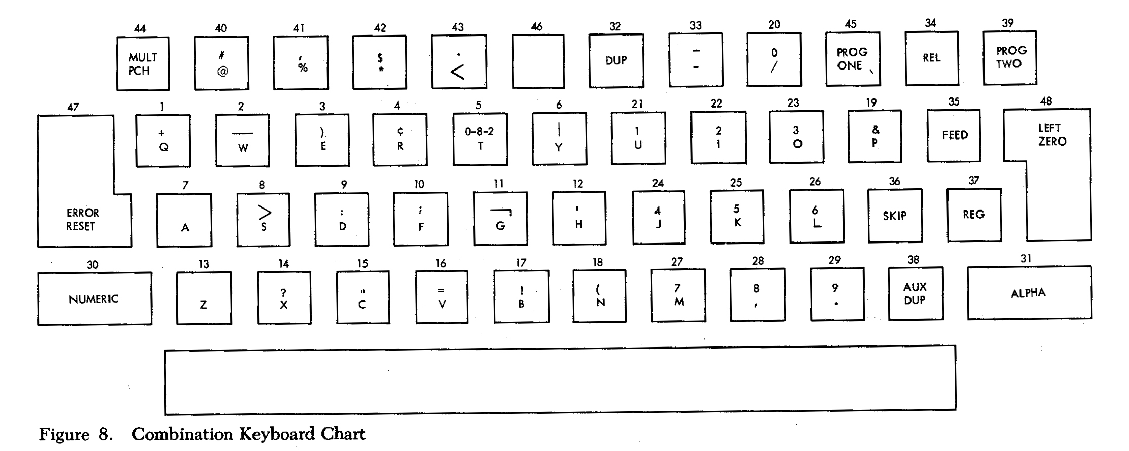
  • There are several distinct areas of special function keys.
  • One of the keys has 5 symbols on it, another has 4 symbols; in both cases ! is one of them!
  • Another couple keys have 3 symbols.
  • The quote key legends are curly-quotes.
  • The main typewriter section is tilted back an additional 1.5°.
There does not seem to be much technical information about CPT machines online.

The PCB has a keyed 26-pin socketed IDC header. This keyboard just has a 26-conductor ribbon cable. But that may not be original and it may have had a DB-25 like the newer model appears to. The strain relief does need a flat cable, though. Only 20 of the pins are actually connected. Tracing the circuit they are:
  • ground (5 pins).
  • +5V (2 pins).
  • some other power (2 pins).
  • output from the controller (7 pins).
  • 2 more TTL outputs.
  • 2 more TTL inputs.
Mostly, it's 74-series TTL. But the controller, 80-551276, looks to be custom MOS in a 28-pin DIP package. That's where the other voltage goes.
Cortron-80-551276.jpg
Cortron-80-551276.jpg (794.93 KiB) Viewed 3955 times
Apparently already in April 1982 these were a surplus item from Fair Radio. Here is the ad:
Cortron-keyboard-ad.png
Cortron-keyboard-ad.png (87.06 KiB) Viewed 4360 times
The copy suggests that the missing voltage is -12V, but one hesitates to just apply that and see what happens, because that could fry something.

Fortunately, 28-pin MOS with data and power connections to the specific pins sounds just like the Cortron variant of the Xerox Diablo keyboard. There the chip is called an MM5873. That is also the manufacturer's part number given in HP catalogs for their part 1820-1849, with a vendor of ITW. I don't actually know what HP keyboard that is; the 2645A that has the same switches has its own control logic.

The final confirmation that 80-551276 is MM5873 comes from kfazz's Diablo work where it can be seen in one of their photos, zoomed in here:
kfazz_20190715_183321.jpg
kfazz_20190715_183321.jpg (266.41 KiB) Viewed 4360 times
The Diablo Model 1610/1620 Maintenance Manual is amazingly detailed, even for the time and even compared to the likes of DEC, HP, and IBM. Not only does it have schematics, it even has a drawing showing the conventions for the other drawings. It includes simplfied versions of the data sheets for every chip, leaving out what would be important when designing with it, but keeping what is needed to understand the logic. One of these is for the MM5873.

With power sorted out, I built the converter. In order to work out the signal details, I wired them all up:
CPT-converter-IDC.jpg
CPT-converter-IDC.jpg (628.39 KiB) Viewed 3955 times
But it could probably be simpler. I connected the flip-flop logic that monitors key state to D0 to allow for the possibility of handling key press via interrupt. But, in the end, that made the NKRO behavior unnecessarily hard. So, treat the contiguous eight pins 4,17,5,18,6,19,7,20 as a single 8-bit byte read at once, with 7 bits of code and the high bit make vs. break. Of the two inputs to the keyboard, 22 needs to be high and 23 needs to be low. I suspect this is some sort of reset / busy setup, but didn't trace out the remaining details of the circuit. I did try leaving them at high-Z and it only worked for one and a half key presses, so some handshake was wrong.

Unlike the earlier HP effort that did the 12V power separately, this adapter board drives the boost converter off USB power. Together with the Teensy and keyboard TTL, it draws about 315mA total and QMK configures for 500, so that should be fine.

In putting together a default QMK layout, I ignored more of the existing legends than usual to give something more useful.
Last edited by MMcM on 06 Dec 2020, 21:46, edited 1 time in total.

User avatar
JP!

10 Aug 2020, 06:48

Stellar work and research as usual. Also I must say, you have the best looking of these CPT word processor keyboards. The black just looks cooler than the standard beige ones.

Bull_ttx90_System_s1.jpg
Bull_ttx90_System_s1.jpg (29.92 KiB) Viewed 4340 times

User avatar
ddrfraser1

11 Aug 2020, 01:41

Sick dude. I tell ya, those wp keebs are the best looking.

User avatar
Haquilus

11 Aug 2020, 22:39

That is one hell of a keyboard

MMcM

06 Dec 2020, 21:52

I finally got a chance to check out the newer board.
CPT-side-by-side.jpg
CPT-side-by-side.jpg (392.26 KiB) Viewed 3955 times
Under any other circumstances, it would count as huge. It's still not exactly small next to its older sibling, but definitely not as much of a monster.

The PCB is more or less identical.
Cortron-55-500582.jpg
Cortron-55-500582.jpg (515.82 KiB) Viewed 3955 times
Cortron-80-551646-rev-C.jpg
Cortron-80-551646-rev-C.jpg (870.1 KiB) Viewed 3955 times
The CMOS encoder is a slightly different part number. I can't tell any difference in behavior.
Cortron-80-551770.jpg
Cortron-80-551770.jpg (83.71 KiB) Viewed 3955 times
The same converter works, with just a different connector.
CPT-converter-DB25.jpg
CPT-converter-DB25.jpg (819.92 KiB) Viewed 3955 times
I don't know whether it actually changed from IDC or the earlier board got a replacement after being separated from its terminal.

mr_a500

06 Dec 2020, 23:48

MMcM wrote:
10 Aug 2020, 05:36
This Cortron keyboard was part of a CPT 8000 series word processor from the end of 1979.
CPT-case-black.jpg

It is more than 2 ft. long. The case is steel, so the whole weighs 9.5 lbs.
What a coincidence... just yesterday I was checking out that terminal. I've seen it before. I definitely prefer the black key version. That keyboard has to be one of the widest I've ever seen... aside from this monolith:

Monolith.jpg
... and a couple later dedicated video editing terminals.

MMcM

25 Apr 2022, 04:06

The keyboard for the Sperry-Univac UDS-2000, pictured in the Wiki, uses a similar PCB, Cortron 55-500252. It comes in three styles, typewriter, adding machine, and keypunch. The photos in the Wiki are of the adding machine style, with 0 at the bottom (replacing part of the space bar). Here is the keypunch style.
Sperry-Univac-UDS-2000-case.jpg
Sperry-Univac-UDS-2000-case.jpg (267.91 KiB) Viewed 2939 times
This example also has the previous rev of the PCB;
Cortron-80-551633-D-bottom.jpg
Cortron-80-551633-D-bottom.jpg (387.61 KiB) Viewed 2939 times
Note that among the differences around the 0 key the adding machine one has some cut traces. I do not know whether this is a further customization or part of the standard production.

Once again, the work is done by the non-programmable 80-551276 MOS encoder chip. Some 74-series logic and a 555 timer implement the actual parallel protocol.
  • The REPEAT function is handled inside the keyboard.
  • Only 5 keys on the sides send break codes: HEX, RESET, NUMERIC, ALPHA, LCA.
  • The rising STROBE signal once again comes not from the corresponding chip output but the more complex state of the circuit.
Again the cable has 25-pins in a 2x13 IDC layout with a pin blocker to which the arrow points.

With that and the needed -12V, a converter looks very much like those above.
Sperry-Univac-UDS-2000-converter.jpg
Sperry-Univac-UDS-2000-converter.jpg (397.56 KiB) Viewed 2939 times
All the even (blocker side) pins are ground. The cable is not straight-through, with some of the data pins slightly rearranged from the PCB numbering.

With 53 keys, 2 of which aren't usable by the converter, and no number row, it feels much more like a 40% than a 60%.

User avatar
MathematicalJ

28 Apr 2022, 00:14

That is a beautiful piece of kit. Those PCBs are super sexy.

retrocatgaming

29 Apr 2022, 02:57

MMcM wrote:
25 Apr 2022, 04:06
The keyboard for the Sperry-Univac UDS-2000, pictured in the Wiki, uses a similar PCB, Cortron 55-500252. It comes in three styles, typewriter, adding machine, and keypunch. The photos in the Wiki are of the adding machine style, with 0 at the bottom (replacing part of the space bar). Here is the keypunch style.
Sperry-Univac-UDS-2000-case.jpg

This example also has the previous rev of the PCB;
Cortron-80-551633-D-bottom.jpg

Note that among the differences around the 0 key the adding machine one has some cut traces. I do not know whether this is a further customization or part of the standard production.

Once again, the work is done by the non-programmable 80-551276 MOS encoder chip. Some 74-series logic and a 555 timer implement the actual parallel protocol.
  • The REPEAT function is handled inside the keyboard.
  • Only 5 keys on the sides send break codes: HEX, RESET, NUMERIC, ALPHA, LCA.
  • The rising STROBE signal once again comes not from the corresponding chip output but the more complex state of the circuit.
Again the cable has 25-pins in a 2x13 IDC layout with a pin blocker to which the arrow points.

With that and the needed -12V, a converter looks very much like those above.
Sperry-Univac-UDS-2000-converter.jpg

All the even (blocker side) pins are ground. The cable is not straight-through, with some of the data pins slightly rearranged from the PCB numbering.

With 53 keys, 2 of which aren't usable by the converter, and no number row, it feels much more like a 40% than a 60%.

Just recently found one of these! I think it’s the typewriter version because it looks a bit different from the keypunch and adding machine variants. Would be awesome to get it converted over to USB. Do you happen to have a guide on how you made your converter?
Attachments
0545008D-58D4-4AF8-BB28-51199B26E1F4.jpeg
0545008D-58D4-4AF8-BB28-51199B26E1F4.jpeg (3.04 MiB) Viewed 2782 times

MMcM

29 Apr 2022, 17:48

I admit I have never seen the typewriter style, but I believe yours is another variant of keypunch, adding | and losing { and }.

Compare with this, for instance, particularly keys 20-29.

More details on the converter here. Do take note of the limitations of such a non-destructive conversion, though.

retrocatgaming

29 Apr 2022, 18:25

MMcM wrote:
29 Apr 2022, 17:48
I admit I have never seen the typewriter style, but I believe yours is another variant of keypunch, adding | and losing { and }.

Compare with this, for instance, particularly keys 20-29.

More details on the converter here. Do take note of the limitations of such a non-destructive conversion, though.

Interesting! Perhaps there are other variants of the keypunch model besides the ones documented. Would you mind if I PM you? Just have a question about converting this board!

Post Reply

Return to “Workshop”