If you don't care about the long-winded backstory of my project, scroll down to the section labeled "Skip here for the actual question".
I'm working on a retrofit project involving a Zenith Turbosport 386. I set myself a limitation that I couldn't do anything to it that couldn't be undone in the future. Part of that has been adapting it's XT 5 pin DIN keyboard to USB. But I also wanted to be able to remap keys because some of the keys I use a lot are not easily accessible. For instance, F12 is accessed via Fn+F2. I also wanted to be able to add macros and map a windows key. I stumble across this forum and the excellent Soarer's firmware. Since there were turnkey versions of this on eBay, I decided to go that route and bought a 5 pin DIN to USB cable that had the microcontroller integrated and the firmware already flashed.
Unfortunately, that proved to be unreliable. It seemed that most times that I plugged it in, it would detect my keyboard incorrectly and many of the keys would be mapped to weird keys. I'd have to unplug and replug in the keyboard many times to get all the keys to finally work. Not ideal.
Long story slightly less long, I decided to roll my own. With a Seeed Studio Xiao and copious amounts of googling and trial and error, I have a functional keyboard that works correctly every time it's plugged in. I still have some small things to overcome, but I'm typing this on it now. It works well. That brings us to my actual question:
--Skip here for the actual question --
The keyboard has extra LED indicators for Power, Hard Drive, and Floppy Drive. There are no extra wires in the original cabling, so I have to assume that the computer sends regular PS/2 commands to the keyboard just like the other LEDs. I had hoped that they just used the next value up from where the standard LED indexes stop, but unfortunately, that didn't work. Does anyone know what they might have used? I have 2-way communication with the keyboard working. I can control the LEDs for Num Lock, Caps Lock, and Scroll Lock with no issue. I've also found that if I send 255 as the LED index value, all of the lights is flash on, then off. I think that's the keyboard resetting. So I may be causing the keyboard controller to get confused or to overflow or something. Also, some values in the 200's will lock the keyboard up until it's power cycled.
If nobody here knows, I may see if I can hook something up to the original hardware and see what it sends for the power on LED. That's all I'll be able to check though. I'm retrofitting this computer because I was unable to get the original hardware to boot. Even after purchasing 3 different units to try to troubleshoot. But it will, at least, turn on the power LED on the keyboard.
Anyone familiar with how manufacturers implemented special features on the PS/2 protocol?
-
Muirium

- µ
- Location: Edinburgh, Scotland
- Main keyboard: HHKB Type-S with Bluetooth by Hasu
- Main mouse: Apple Magic Mouse
- Favorite switch: Gotta Try 'Em All
- DT Pro Member: µ
One of these?
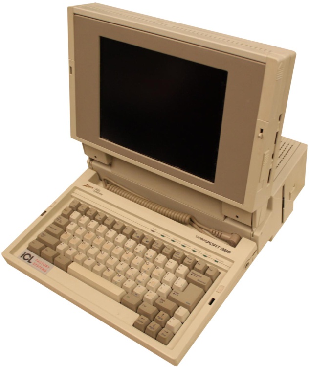
https://www.computinghistory.org.uk/det ... Sport-386/
Which protocol are you using: XT or AT? Note: I do *not* mean which shape of connector, as DIN 5 can be both.
XT is strictly monodirectional. If it's speaking XT, I suspect some signalling out-of-band entirely. And even if it's AT, you've already explored the obvious choices. Notably: both XT and AT use only 4 of the DIN socket's 5 pins, if you catch what I mean…
-
Sheepless

- Location: United Kingdom
- Main keyboard: IBM Model F122
- Main mouse: Logitech G502
- Favorite switch: IBM buckling spring
Andries Brouwer's "keyboard scancodes" document says "sequences involving eb are often used for manipulating extra LEDs", and gives these examples:
So I'd start by trying two and three byte sequences starting with eb.The Chicony keyboard needs command sequences eb 00 xy, with xy = 01 for the Moon LED and xy = 02 for the zzZ LED.
The IBM EZ Button keyboard needs command sequences eb 00 xy, with xy = 01 for the Msg LED, xy = 02 for the CD LED, xy = 04 for the Power LED, xy = 10 for the Talk LED, and xy = 20 for the Message Waiting LED.
The IBM Rapid Access keyboard needs command sequences eb 00 xy, with xy = 04 for the Suspend LED and xy = 20 for the Mute LED.
The IBM Rapid Access keyboard II needs the command sequences eb 71 and eb 70 to switch the Standby LED on and off.
The Logitech Internet Keyboard has an additional amber LED. It is turned on by sending eb, and then blinks about once a second. It is turned off again by ec.
-
Muirium
- µ
- Location: Edinburgh, Scotland
- Main keyboard: HHKB Type-S with Bluetooth by Hasu
- Main mouse: Apple Magic Mouse
- Favorite switch: Gotta Try 'Em All
- DT Pro Member: µ
I did not know this existed. Thanks for that. 
https://www.win.tue.nl/~aeb/linux/kbd/scancodes.html
Specifically:
https://www.win.tue.nl/~aeb/linux/kbd/s ... l#LEDmanip
https://www.win.tue.nl/~aeb/linux/kbd/scancodes.html
Specifically:
https://www.win.tue.nl/~aeb/linux/kbd/s ... l#LEDmanip
-
Sheepless
- Location: United Kingdom
- Main keyboard: IBM Model F122
- Main mouse: Logitech G502
- Favorite switch: IBM buckling spring
It's a treasure trove of information, if you need to interact with a pre-USB keyboard at a low level.Muirium wrote: ↑20 Dec 2023, 16:56I did not know this existed. Thanks for that.
https://www.win.tue.nl/~aeb/linux/kbd/scancodes.html
Specifically:
https://www.win.tue.nl/~aeb/linux/kbd/s ... l#LEDmanip
-
coder
- Location: St. Louis, MO
- Main keyboard: Durgot Taurus K310
- Main mouse: Anything nearby with a cord and no extra buttons
- Favorite switch: Whatever the Alps in NEC Powermate Portables are
Yep! That's what I'm working on! Here's mine in it's half-finished-but-probably-never-truly-finished form:
.
.
.
.
.
.
I've been using the computer as my work computer (I'm a software developer, it's been fun) as I developed the keyboard's firmware. It's actually quite usable now. I've remapped some keys to give myself easier access to keys I use a lot. I also hard coded a couple macros. I plan to add two way serial support so I can change key mapping, macros, layers, etc. to the keyboard without getting the Arduino compiler involved. But for now, I'm really happy with it.
.
- Ooooh the vintage purists are gonna hate me! But I've gone through great pains to make sure everything I do is 100% reversible.
- 20231220_212437.jpg (2.56 MiB) Viewed 2118 times
- I had to replace the original cable. The rubber was cracking and falling off. Lucky for me, you keyboard guys like your cables coiled, so a suitable replacement was readily available! So thanks! :D
- 20231220_212454.jpg (2.57 MiB) Viewed 2118 times
- This is the back of the original keyboard port with it's original short connector and my custom adapter cable plugged into that. My cable was made from IDE ribbon wiring and two rows of pin header superglued together to form a 2x3 array. Then one pin was cut to make 5 pins total.
- 20231220_212622.jpg (1.38 MiB) Viewed 2118 times
- The other end of my custom cable, another pin header, this time in one long 5 pin row. The brains are supplied by a Seeed Studio Xiao microcontroller running custom firmware I cobbled together from some Arduino libraries that I modified to suit my needs.
- 20231220_212742.jpg (1.34 MiB) Viewed 2118 times
- And in case anyone cares to know, the wizard behind the curtain is the guts of a Lenovo X1 Tablet Gen 3 with a Core i7 running Windows 10. Still working out the specifics of where and how it's going inside the case. There's also a port replicator to supply additional I/O. But my promise to make it 100% reversible makes exposing that I/O... "interesting".
- 20231220_210555.jpg (2.37 MiB) Viewed 2118 times
I've been using the computer as my work computer (I'm a software developer, it's been fun) as I developed the keyboard's firmware. It's actually quite usable now. I've remapped some keys to give myself easier access to keys I use a lot. I also hard coded a couple macros. I plan to add two way serial support so I can change key mapping, macros, layers, etc. to the keyboard without getting the Arduino compiler involved. But for now, I'm really happy with it.
-
coder
- Location: St. Louis, MO
- Main keyboard: Durgot Taurus K310
- Main mouse: Anything nearby with a cord and no extra buttons
- Favorite switch: Whatever the Alps in NEC Powermate Portables are
Thank you so much for the information. I hadn't come across that page yet. I did manage to find out how to control the other LEDs though! I decided to brute force it last night. I figured it was probably using the same two byte method that the other LEDs were, just with a different begging byte. All of the documented PS/2 commands are up at the upper limit of a byte, so I figured I'd need to head downward. So I programmed the caps lock key to send the two byte message, then subtract one from the first byte so on the next keypress, it could try again. I also had it write a message out to the serial port that said what number it was on. I kept the second byte static sending a "1" figuring it probably followed the same pattern as the regular LEDS.
At 0x9F (159 in decimal) I finally saw results. All of the "special" LEDS lit. Unexpectedly, I also got an alarm! lol. I wrote down the number and continued down to see if things changed. As I did, various LEDs went out and the power LED changed from yellow to flashing red, then to green, and finally to solid red. All the while, the alarm sounded.
I continued farther to see if anything else would happen. I didn't really expect it would. But I was wrong. As I reached 0x8F (143), I started the cycle of LEDs over. Just as before, they all lit, with the power light yellow. This time, however, the alarm was blissfully silent. That was, until I got to flashing red. This time though, it sounded the alarm momentarily and with a few second gap in between. Much to my delight. I went through the full cycle. All the way to 0x80 (128). Once I went below that, no changes happened. Importantly though, the power LED remained on it's last set value (constant red, in this case). There doesn't seem to be a way to turn off the power LED once it's turned on. You have to reset the keyboard.
I don't know if anyone cares, but I did figure out how the actual command works. It's not a two byte command like the regular LEDs. It's a single byte. The diagram below shows how it works:
.
.
The first 3 bits are 100 and are static. Following those are 1 bit that indicates if the constant alarm should sound. 1 for yes, 0 for no. After that are two bits that indicate the color that the power LED should be. In my example, it's set to 01, which would make the LED green. The diagram shows the values for the other colors. Following that is a single bit indicating if the HDD LED should be lit, and then finally, a bit that determines if the Floppy Drive LED should be lit.
.
I was able to control the LEDs and alarm as I pleased using this single byte command. I'll also note that the keyboard does not respond with 0xFA (ACK) when this command is sent. So there you go. It's working! You can see it in my earlier post The power light is set to come on once the keyboard is initialized now.
At 0x9F (159 in decimal) I finally saw results. All of the "special" LEDS lit. Unexpectedly, I also got an alarm! lol. I wrote down the number and continued down to see if things changed. As I did, various LEDs went out and the power LED changed from yellow to flashing red, then to green, and finally to solid red. All the while, the alarm sounded.
I continued farther to see if anything else would happen. I didn't really expect it would. But I was wrong. As I reached 0x8F (143), I started the cycle of LEDs over. Just as before, they all lit, with the power light yellow. This time, however, the alarm was blissfully silent. That was, until I got to flashing red. This time though, it sounded the alarm momentarily and with a few second gap in between. Much to my delight. I went through the full cycle. All the way to 0x80 (128). Once I went below that, no changes happened. Importantly though, the power LED remained on it's last set value (constant red, in this case). There doesn't seem to be a way to turn off the power LED once it's turned on. You have to reset the keyboard.
I don't know if anyone cares, but I did figure out how the actual command works. It's not a two byte command like the regular LEDs. It's a single byte. The diagram below shows how it works:
.
- 20231221_013035.jpg (460.69 KiB) Viewed 2091 times
The first 3 bits are 100 and are static. Following those are 1 bit that indicates if the constant alarm should sound. 1 for yes, 0 for no. After that are two bits that indicate the color that the power LED should be. In my example, it's set to 01, which would make the LED green. The diagram shows the values for the other colors. Following that is a single bit indicating if the HDD LED should be lit, and then finally, a bit that determines if the Floppy Drive LED should be lit.
.
I was able to control the LEDs and alarm as I pleased using this single byte command. I'll also note that the keyboard does not respond with 0xFA (ACK) when this command is sent. So there you go. It's working! You can see it in my earlier post
-
coder
- Location: St. Louis, MO
- Main keyboard: Durgot Taurus K310
- Main mouse: Anything nearby with a cord and no extra buttons
- Favorite switch: Whatever the Alps in NEC Powermate Portables are
It's using AT. It has a switch to allow it to use XT, but I have no plans to change it. And yes, it was convenient that it only needed 4 of the wires as the replacement cable I bought was originally USB and only had 4 conductors inside. Serendipity. I did wire the full 5 wires that the original ribbon has on the Arduino side of things. But the extra wire is just a second ground and they're just soldered together at the Arduino.Muirium wrote: ↑20 Dec 2023, 12:02Which protocol are you using: XT or AT? Note: I do *not* mean which shape of connector, as DIN 5 can be both.
XT is strictly monodirectional. If it's speaking XT, I suspect some signalling out-of-band entirely. And even if it's AT, you've already explored the obvious choices. Notably: both XT and AT use only 4 of the DIN socket's 5 pins, if you catch what I mean…