Bringing the IBM PC XT into the 21st Century

User avatar
wcass

03 Jul 2012, 15:40

Soarer wrote:
wcass wrote:... the type of capacitor formed by the pads is polar - serving the same purpose as the diodes in conductive switches.
I don't think it's polar - it doesn't need to be. When the switch is closed, the capacitance is lowered which when strobed increases the rate of change of voltage at the sensing side, hence increasing the voltage sensed at a given time after the strobe above some threshold in the sensing circuit. Any other path to the sensing would have to go through multiple switches, but the switches in other columns have their strobe lines grounded which I guess quells the signal.
Thanks for the clarification.

Do you know the purpose of the pad and dots that are not connected to anything? or should we still call these "magic pads" and "magic dots".

Parak

03 Jul 2012, 16:49

The dots are simply there to raise the switch foot to the same level as the pads. Also notably there's two types of the switch pad placements, where the pads are mirrored. The dots are actually the only useful frame of reference for placing the pads correctly that I've found, as the center of the switch does not pass strictly between the pads.

User avatar
Soarer

03 Jul 2012, 17:08

wcass wrote:Do you know the purpose of the pad and dots that are not connected to anything? or should we still call these "magic pads" and "magic dots".
I wonder if a switch is effectively a series of three capacitors...

Code: Select all

------|a|b|
          |
--------|c|

     /  |  \
bottom top hammer
Which may be quivalent to ...

Code: Select all

-----||--||--||-----
     a   b   c
Where a is constant, and b and c both change if the switch is pressed. But then I get confused because series capacitances don't combine by adding, rather 1/(1/a+1/b+1/c), so I'm not sure how that would reproduce the observed decrease in rise time :?

edit: or is it a decay? dunno, need to confer with dfj...
Last edited by Soarer on 03 Jul 2012, 17:42, edited 1 time in total.

User avatar
wcass

03 Jul 2012, 17:30

Parak wrote:The dots are simply there to raise the switch foot to the same level as the pads. Also notably there's two types of the switch pad placements, where the pads are mirrored. The dots are actually the only useful frame of reference for placing the pads correctly that I've found, as the center of the switch does not pass strictly between the pads.
I have found that the edge of the magic pad closest to the top pad is the centerline of the switch. it is very easy to mirror a collection of items in the drafting sofware i use.

I suppose that i should post my switch-to-switch measurements tomorrow as i will have the day off.

Parak

03 Jul 2012, 19:57

Here are the kicad libs that I did - I think they're as exact as I could get them barring some glaring overlooked error. It still needs to be validated either via etching or a small pcb. There are 4 footprints, reversed and regular, and their versions where they have no mask - meaning pads are fully covered by the pcb laquer. The F has a layer of resin over the pads that protects them, so this is intended to simulate that a little, but again, either version has yet to be tested.
libs.zip
(1.08 KiB) Downloaded 201 times

User avatar
Ratfink

03 Jul 2012, 20:43

I must say, I find this to be a very interesting idea. When I had an XT keyboard open fully (I still wish I hadn't pried off the spacebar (broke one of the feet getting it back together, but glued it back together), but it was a learning experience), I noticed it looked very modular, and I thought it might be neat to try giving one a different layout eventually. However, I like many things about the original layout, like Esc and Ctrl being within easy reach. I guess the layout will still be customizable to an extent with this mod.

Side note: Has anyone else noticed that the Teensy can be mounted in the space for that rubber block on the original cable, and that with a bit of grinding with a dremel tool, the USB connector can then be made accessible from the outside? A detachable cable for this might be really nice.

User avatar
wcass

03 Jul 2012, 21:06

Parak wrote:Here are the kicad libs that I did - I think they're as exact as I could get them barring some glaring overlooked error. It still needs to be validated either via etching or a small pcb. There are 4 footprints, reversed and regular, and their versions where they have no mask - meaning pads are fully covered by the pcb laquer. The F has a layer of resin over the pads that protects them, so this is intended to simulate that a little, but again, either version has yet to be tested.
libs.zip
Woohoo! First file submition!
I have two sheets of .031 copper clad. has anyone ever done DIY etching before? if so, please step up!

User avatar
Ratfink

03 Jul 2012, 21:46

I've etched PCBs before, but only single-sided boards. I'm guessing that for a double sided board, the iron-on method I used wouldn't work very well, as things would tend to get misaligned. For all I know, though, there's some obvious trick that I'm just not thinking of. Maybe a CNC mill would work better.

JBert

03 Jul 2012, 22:24

Couldn't you drill two holes through the unetched board to have alignment markers? Adding two extra black dots to the print films shouldn't be too hard...

User avatar
wcass

05 Jul 2012, 18:05

I will be doing a poll to decide the name in the next few days. If you don’t see a name that you like on this list, please submit it soon!

• Model F NG
• Model FU
• FoeniX
• neXT Model F
• Model F Deskthority Edition
• Model F XTended
• Model F XTreme
• XT+
• XT Pro
• NXT
• modFX

It is legally ambiguous whether or not we could incorporate “IBM” in the name. One might think this is analogous to an automobile restoration/customization. The keyboard would still be about 90% original. Do we have any IP attorneys out there that could advise on this?

After the name is chosen, we will settle on one of the layout choices. If you don’t like any of the key layouts previously posted, please submit one – or just describe it to me and I will do a mock-up.

On another note, I used Parak’s KiCAD libraries (slightly modified) to design a single switch test module. I will start building that this weekend.

Also, I am in communications with a company that does CNC routing of soft materials. I will be getting quotes for our project here. Please let me know if I should ask for replacement foam for the original AT and 122.

bazemk1979

05 Jul 2012, 23:14

- Model F XT pro

User avatar
wcass

06 Jul 2012, 05:54

I've been thinking about the name a lot recently mostly because it is at the top of the todo list.

Upon advice of counsel, I don't think we can include any reference to IBM. Also, there is a whole line of keyboard and pointing devices with names that include XTreme, so that one is out too.

I think I need to remove "Model F" from all submissions so far. "Model F" is a switch type (capacitive buckling spring). So the new keyboard will still be a "Model F" regardless what name we choose and that can be prefixed or postfixed as you please; Model F XT, Model F AT, Model F 122. That leaves us with ...

• FoeniX
• neXT
• NXT
• XT+
• XT Pro
• XTant

That last one is my new favorite.

extant [ɛkˈstænt ˈɛkstənt] adj
1. still in existence; surviving
2. Archaic standing out
[from Latin exstāns standing out, from exstāre, from stāre to stand]

I printed out the switch and then compared it to the PCB - line-up by shining a light through it to check size and position. This led to more tweaking of measured values. I finished the KiCAD design and will try to make 6 one-key boards this weekend.
KiCAD switch test.JPG
KiCAD switch test.JPG (89.14 KiB) Viewed 7742 times

User avatar
didja

06 Jul 2012, 05:57

XTant sounds pretty cool and like the meaning.

andrewjoy

06 Jul 2012, 13:38

IBM FoeniX

Sounds good to me

now I just need to find an XT :). I cannot stop buying model fs I just love them :)

User avatar
wcass

06 Jul 2012, 17:34

The "Name the Keyboard" poll is now open. You can select up to two names and the poll will run till the 16th.
http://deskthority.net/keyboards-f2/nam ... t3194.html

Thanks

User avatar
off

06 Jul 2012, 18:10

Not having a Model F incoming any time soon, but I'm curious: you seem set on using the standard typewriter-stagger, instead of a matrix or symmetrical stagger.. Is it that you don't like those, or that it would probably require buying more keycaps, or that it would be 'harder to market', or?

Great initiative anyhow; am digging the 1.25/1.5u arrow/nav cluster and two-wide bar on the left version!

User avatar
wcass

06 Jul 2012, 18:47

off wrote:Not having a Model F incoming any time soon, but I'm curious: you seem set on using the standard typewriter-stagger, instead of a matrix or symmetrical stagger.. Is it that you don't like those, or that it would probably require buying more keycaps, or that it would be 'harder to market', or?

Great initiative anyhow; am digging the 1.25/1.5u arrow/nav cluster and two-wide bar on the left version!
I have nothing against matrix or symmetrical stagger. If you have an idea you would like to share, please describe it to me and i will do a mock up. I will probably do a poll in 2 weeks to deside on layout.

But even if matrix or symmetrical stagger are not chosen for this build, I am hoping that someone will take up that gauntlet and continue developing new keyboards with Model F switches. The purpose of this project is to prove that you can re-use the Model F switch in a layout that the IBM keyboard designers did not invision 30 years ago. I want to see Unicomp (or other company) start producing the F barrels and hammers and I want to see a "new-from-ground-up" model F controller.

User avatar
Icarium

06 Jul 2012, 19:01

If we manage to make a working PCB I'm sure many mods will follow. I checked out the electronics last night and it is probably possible to replace most of the controller and add additional switches.

Multiple

06 Jul 2012, 19:30

A name describing what you've modded sounds reasonable, but that's just me.

Parak

06 Jul 2012, 20:51

In theory you don't need a drawn out ground trace surrounding every strobe line and trace. Filling in a ground plane on the entire pcb should be equivalent as long as it properly surrounds the lines (disclaimer: untested, obviously).

User avatar
wcass

06 Jul 2012, 21:55

Parak wrote:In theory you don't need a drawn out ground trace surrounding every strobe line and trace. Filling in a ground plane on the entire pcb should be equivalent as long as it properly surrounds the lines (disclaimer: untested, obviously).
I will try this with one of the test switches.

User avatar
Ratfink

06 Jul 2012, 22:13

I think it would be very neat for this mod to also add LEDs to the case of the keyboard. Though that wouldn't be trivial (milling the case to recess the label would be tricky), the LEDs are one of the things I miss most on the XT keyboard.

User avatar
dorkvader

07 Jul 2012, 08:36

Ratfink wrote:I think it would be very neat for this mod to also add LEDs to the case of the keyboard. Though that wouldn't be trivial (milling the case to recess the label would be tricky), the LEDs are one of the things I miss most on the XT keyboard.
You can just drill holes in the case filco TKL style, and place the LED's on a sub-board underneath (or grue them to the bottom of the case.

I think even if people don't install them, having the LED's would be useful. I believe soarer's teensy firmware supports this, so it shouldn't be hard.

I also would like to see matrix or symmetric stagger. Perhaps we can vote on the topic later, once it's part of the design process, but It'd be good to consider them as an option.

User avatar
wcass

07 Jul 2012, 13:39

Adding LEDs is to be an optional part and it will not require drilling holes in the case. I am currently using what i call my Terminal SSK. The caps lock LED is under the caps lock key and the light spills out around the key. It is not as "in your face" as direct lighting but still very noticeable. This picture really doesn't do it justice as the human eye is better at discerning light difference than my camera.
tssk_drawer.JPG
tssk_drawer.JPG (132.7 KiB) Viewed 7669 times

User avatar
wcass

08 Jul 2012, 17:26

DIY PCB

This was my first time making a PCB at home. I thought I would share. If you plan on doing something like this for the first time, first read all of the How-To pages on the net and watch all of the videos on YouTube.

I used pages from a People magazine. I found 3 pages that mostly white, two of which were mostly monochromatic on the other side. I also selected two additional pages to use as tests. The pages were already 10.5 inches tall, so I cut the pages to 7.25 inches wide to make them “Executive” size. The first test page jammed, but the second one went through just fine. All three of the “good” pages jammed the printer just like the first test. I used the back cover as it was thicker and it passed through the printer just fine but bubbled slightly. A second attempt to print on a magazine cover produced a lot of bubbles, so now I believe that the outside covers of some magazines are covered with something that makes them unsuitable for toner transfer. I found more pages and just kept trying until I got both sides printed – and yeah, I had to clear about 8 more jams.

Most of the training material recommends using Scotch Brite by name. I used a brand new Scotch Brite pad but it didn’t seem to polish the copper at all no matter how hard I rubbed. I ended up using an extra-fine grit sanding block and stopped when the copper was shiny. I cleaned with alcohol, positioned the first magazine page, and started to iron. I ironed for about 5 minutes, flipped the PCB over, positioned the second magazine page, and ironed for another 5 minutes. I rinsed with water and pealed the paper off. Like a lot of printers, mine leaves stripes in some of the fills. I had to touch up these and a few other spots with a Sharpie.
top_toner.JPG
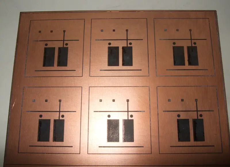
top_toner.JPG (102.38 KiB) Viewed 7633 times
bot_toner.JPG
bot_toner.JPG (101.32 KiB) Viewed 7633 times
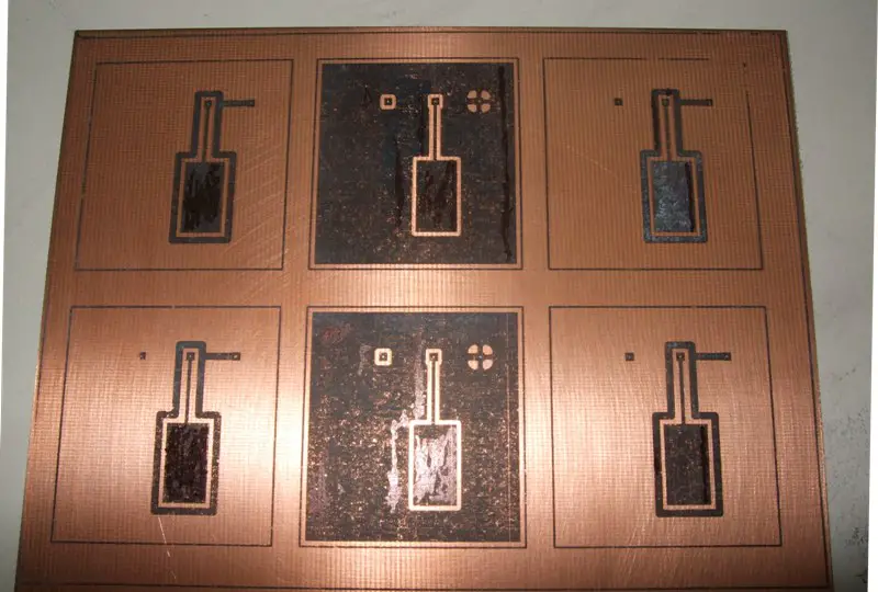
I chose to etch with hydrogen peroxide and hydrogen chloride because I had both on hand. Mixed in a 2:1 it took about 5 minutes to etch. I rubbed the copper with a small piece of sponge during the process.
top_etched.JPG
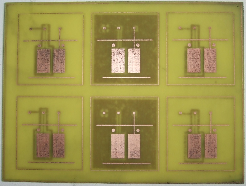
top_etched.JPG (116.11 KiB) Viewed 7633 times
bot_etched.JPG
bot_etched.JPG (138.92 KiB) Viewed 7633 times
top_clean.JPG
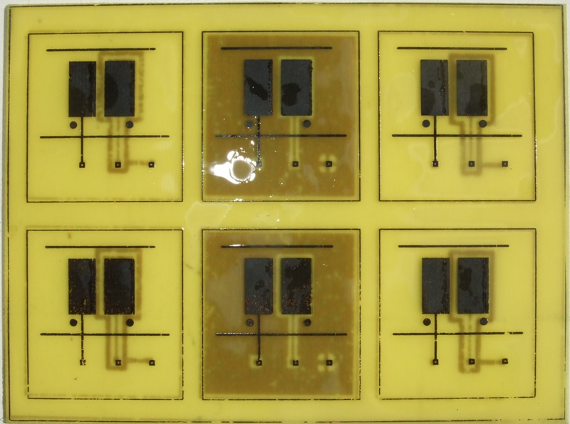
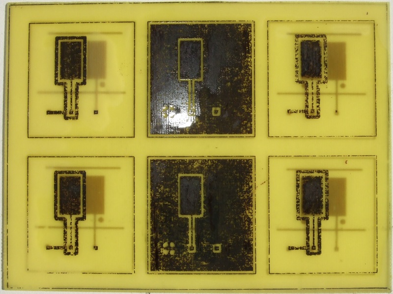
top_clean.JPG (104.76 KiB) Viewed 7633 times
bot_clean.JPG
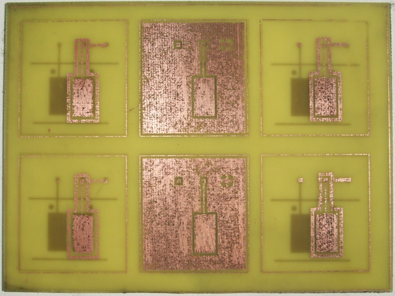
bot_clean.JPG (131.97 KiB) Viewed 7633 times
x-ray.JPG
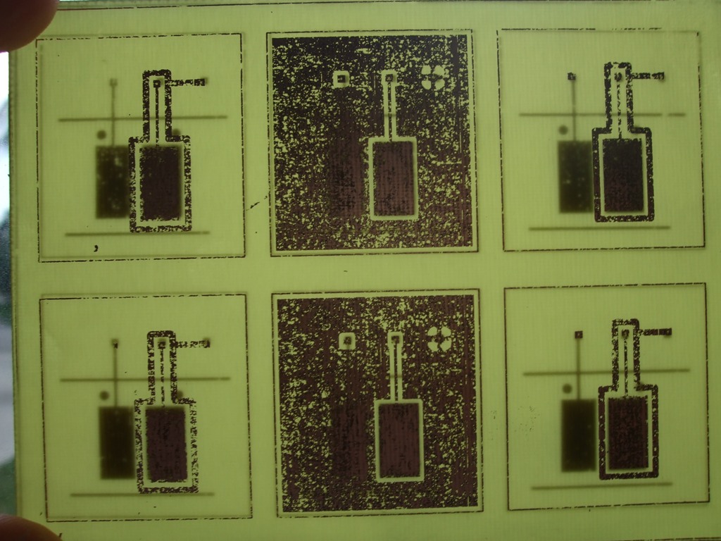
x-ray.JPG (186.71 KiB) Viewed 7633 times
I am not happy with the end result. The two sides did line up pretty nicely, but far too much of the toner flaked off leaving pitted fills and broken traces. But I will still wire these up to see if they trigger the controller. If they work then it tells us that the controller will handle a signal far from perfect, and if not, it is something worth knowing.

I have a Brother laser printer at home and have heard that these have a different fuser temperature (and toner formulation) than other laser printers. Perhaps the sanding block was too abrasive or I didn’t abrade enough. I have plenty of blank copper clad remaining, so please comment if you have any suggestions on improving my process.

User avatar
Ratfink

08 Jul 2012, 18:08

From the little bit of etching I did, I found that the Scotch Brite works best with acetone. When you're done with that, wipe the whole thing with an acetone-moistened paper towel, and the board should be very clean and shiny. Rinsing it with water afterwards might be a good idea.

User avatar
wcass

08 Jul 2012, 21:16

5 out of 6 passed conductivity test on the top side, but all failed conductivity test on the back side, so i will not be wiring these up.

Thanks, Ratfink, i will try your suggestion. At work i have HP, Xerox, and Ricoh printers and have some glossy paper that should jam less.

bazemk1979

09 Jul 2012, 15:04

the more im watching this mod the more clueless i become.... hope newbies like me can tackle this thing if this mod turns out to be sucsesfull mod.

User avatar
wcass

09 Jul 2012, 17:13

The kit will be very simple and you will have step-by-step instructions.

What i am doing is designing, building, and testing the new parts. These will be professionally manufactured for the kits, so the quality will be much higher.

bazemk1979

09 Jul 2012, 19:47

thanks, I already have second NIB XT waithing on me to purchase it, box little distressed but still have the seals on the styrofoam non removed or cut out :-)

Post Reply

Return to “Workshop”