Amazing! I'll be signing up shortlychzel wrote:$169 is the cost of 10 PCBs, add to that shipping and expenses, and you get $21 per PCB.
Let's create the FSSK/FEXT = DONE !!!!
-
scottc

- ☃
- Location: Remote locations in Europe
- Main keyboard: GH60-HASRO 62g Nixies, HHKB Pro1 HS, Novatouch
- Main mouse: Steelseries Rival 300
- Favorite switch: Nixdorf 'Soft Touch' MX Black
- DT Pro Member: -
I'm sorry idollar but I've had to withdraw myself from the prototype testing list. I couldn't fit my SSK in my luggage from home so I'll be without it for a few months and thus won't be any help for prototyping.
-
Techno Trousers

- 100,000,000 actuations
- Location: California
- Main keyboard: IBM Model F-122
- Main mouse: Mionix Naos
- Favorite switch: Capacitive Buckling Spring (Model F)
- DT Pro Member: 0159
I'd vote for starting with the FEXM as well. We need to get a few more folks interested in testing that--it could ultimately prove more popular than the FSSK, if the word gets out. M-101s are abundant and affordable, so it would be a great way to have an F feeling keyboard without breaking the bank.
Could I trouble you to price for U.S. shipping as well? I know it will cost more. If there's enough interest from here in the U.S. I could be a reship point as well.
Could I trouble you to price for U.S. shipping as well? I know it will cost more. If there's enough interest from here in the U.S. I could be a reship point as well.
-
idollar

- i$
- Location: Germany (Frankfurt area)
- Main keyboard: IBM F or M
- Favorite switch: BS
- DT Pro Member: -
We can order 10,15,20 from the site that I have posted.neverused wrote: ↑Please forgive my ignorance, I see $169 and 21$ in the post above, may I ask which is the final per pcb cost? If it is $21 then I will be sure to add my name to the spreadsheet as soon as I can get a proper computer and not my phone.
Thank you,
neverused
Currently we are exactly 10.
$ 169 / (10 - 2) = $ 21 per PCB
The 2 that I have subtracted are the ones that I will keep and first test.
There is currently an offer of $50 minus.
There is some risk with this order. I have checked the PCB 1000 times and I will print it and check it again. But it may not work. This is why I have proposed to do a mini group buy, to share the risk.
I am proposing that the interested people contribute at procuring time with $21. If the prototype work, there will be a need to add some money to ship again from my location. All at cost. The return of my work are the two PCBs that I have mentioned above.
I will not hide my intention to make all this work public. So one could also wait for a tested PCB before ordering. The people that will join in this initial phase will do it to contribute to the risk sharing with me, to ensure that all the others benefit latter from a tested design.
Note that additional to the need to test the PCBs, the resulting keyboard will not have a top-metal-plane. I do not know how will this impact the noise PCB.
Ordering 15 are the same unitary amount.
I hope that this post clarifies. I am trying to be as honest as I can.
Last edited by idollar on 03 Jan 2016, 20:35, edited 1 time in total.
-
idollar
- i$
- Location: Germany (Frankfurt area)
- Main keyboard: IBM F or M
- Favorite switch: BS
- DT Pro Member: -
This has an easy solution: two future group buys, one in Europe and a second in the USA. Additional ones as needed.Techno Trousers wrote: ↑I'd vote for starting with the FEXM as well. We need to get a few more folks interested in testing that--it could ultimately prove more popular than the FSSK, if the word gets out. M-101s are abundant and affordable, so it would be a great way to have an F feeling keyboard without breaking the bank.
Let me think about it.
It means additional time from my side and my holidays are over.
Also, the PCB will be bigger and therefore more expensive.
Could I trouble you to price for U.S. shipping as well? I know it will cost more. If there's enough interest from here in the U.S. I could be a reship point as well.
Remember that you will need some F flippers also !!!
I would anyhow appreciate non-European people contributing to the risk mitigation. As I said, I will make no money with this. the fair thing would be that the USA guys contribute with some $$s to the prototyping phase also.
I will add a column for this in the Google Spreadsheet.
----------------
Reminder
----------------
I have created the following spreadsheet to collect the interest and contributions in this project.
Click here
Please write down your interest/preferences.
-
chzel

- Location: Athens, Greece
- Main keyboard: Phantom
- Main mouse: Mionix Avior 7000
- Favorite switch: Beamspring, BS, Vintage Blacks.
- DT Pro Member: 0086
My reasoning behind proposing the FEXM as the first PCB is that by testing the full size would get us closer to a known good design to get the FSSK right with the first try.
To be honest though, I'd really prefer the FSSK first.
To be honest though, I'd really prefer the FSSK first.
Idollar raises a really good point here. Be warned that this is a prototype phase, ie potentially lost money. We might only get a '"Thank you, but we failed this time, onto the next prototype." instead of a PCB.idollar wrote: ↑ There is some risk with this order. I have checked the PCB 1000 times and I will print it and check it again. But it may not work. This is why I have proposed to do a mini group buy, to share the risk.
-
idollar
- i$
- Location: Germany (Frankfurt area)
- Main keyboard: IBM F or M
- Favorite switch: BS
- DT Pro Member: -
No problem. Thanks anyhowscottc wrote: ↑I'm sorry idollar but I've had to withdraw myself from the prototype testing list. I couldn't fit my SSK in my luggage from home so I'll be without it for a few months and thus won't be any help for prototyping.
-
idollar
- i$
- Location: Germany (Frankfurt area)
- Main keyboard: IBM F or M
- Favorite switch: BS
- DT Pro Member: -
This or a non-working prototype if you pay the extra shippingchzel wrote: ↑ Idollar raises a really good point here. Be warned that this is a prototype phase, ie potentially lost money. We might only get a '"Thank you, but we failed this time, onto the next prototype." instead of a PCB.
I am simply testing the deskthority culture that I mentioned before
I could sell you the prototypes at $50 or whatever. I will not do it. But if you will benefit from this work you may want to help.
It is up to you guys.
But, yes, lets make it 100% clear:
Be warned that this is a prototype phase, ie potentially lost money. We might only get a '"Thank you, but we failed this time, onto the next prototype." instead of a PCB.
-
hammelgammler

- Vintage
- Location: Germany
- Main keyboard: IBM Model F Unsaver
- Main mouse: G-Wolves Skoll
- Favorite switch: Buckling Spring (Model F)
- DT Pro Member: -
Would it be possible to buy a few PCB's more? I may want another one, so I can build two FSSK (I have two bolt-modded SSK's, so that's kind of nice).
A friend of mine would like to buy one too I think.
Or do you want to do just 10 PCB's to make sure the PCB works?
Edit: Oh and yeah, I know it's just a prototype.
Edit2: I just saw that scott cancelled his order for one protoype, so if I take two we are back to 10 PCB's.
Nevertheless it would be good to know if 11 would be possible for a friend of mine.
But I thought about it. IF the protoypes are working, is the next GB another "only PCB" run, so that you would need to solder the xwhatsit controller in yourself, or would it be a run with the xwhatsit in the integrated into the PCB?
Because I have some xwhatsit left, and wouldn't really need a PCB with it integrated.
-
idollar
- i$
- Location: Germany (Frankfurt area)
- Main keyboard: IBM F or M
- Favorite switch: BS
- DT Pro Member: -
The site that I selected, the same one that wcass used for his PCB, allows to order 10 or 15. There is no option offered in the middle.hammelgammler wrote: ↑ Edit2: I just saw that scott cancelled his order for one protoype, so if I take two we are back to 10 PCB's.
Nevertheless it would be good to know if 11 would be possible for a friend of mine.
I do not know. It depends on the test that we will do. There is little space for the controller in the PCB. We need to see.But I thought about it. IF the protoypes are working, is the next GB another "only PCB" run, so that you would need to solder the xwhatsit controller in yourself, or would it be a run with the xwhatsit in the integrated into the PCB?
-
idollar
- i$
- Location: Germany (Frankfurt area)
- Main keyboard: IBM F or M
- Favorite switch: BS
- DT Pro Member: -
This requires flippers and a xwhatsit controller.neverused wrote: ↑This will require an xwhatsit controller correct? Will the redesigned version be tested at the same time?
I cannot guarantee a redesign of the PCB now.
We are talking about testing the idea that I had some time ago. Just this.
The future will tell.
For the time being this is about contributing with 20 euros to the project, with the option to get a working PCB for this money plus the shipping of the PCB from Europe.
-
wcass

- Location: Columbus, OH, USA
- Main keyboard: ibm model m
- Main mouse: kensington expert mouse
- Favorite switch: buckeling spring
- DT Pro Member: 0185
What thickness PCB are you planning on using?
I didn't see any rivet holes in your final design.
Left Alt looks like it is not connected top-side.
I didn't see any rivet holes in your final design.
Left Alt looks like it is not connected top-side.
-
idollar
- i$
- Location: Germany (Frankfurt area)
- Main keyboard: IBM F or M
- Favorite switch: BS
- DT Pro Member: -
Thanks !!!
1) I plan to print the pcb before placing the order to ensure that they are in the correct place.
2) I plan to drill the holes when I receive the PCB, using the back plate as template. This will ensure that they are exactly in the right place.
They are painted in the drawing below
EDIT: what you see is a screen-dump.
There is no flipper on top. It is just one of the space barrels.
0.8mm.wcass wrote: ↑What thickness PCB are you planning on using?
I have considered them in the design. but they are not painted in the version that I have posted for two reasons:I didn't see any rivet holes in your final design.
1) I plan to print the pcb before placing the order to ensure that they are in the correct place.
2) I plan to drill the holes when I receive the PCB, using the back plate as template. This will ensure that they are exactly in the right place.
They are painted in the drawing below
If you are talking about this (in red)Left Alt looks like it is not connected top-side.
EDIT: what you see is a screen-dump.
- answer.jpg (64.1 KiB) Viewed 5648 times
-
idollar
- i$
- Location: Germany (Frankfurt area)
- Main keyboard: IBM F or M
- Favorite switch: BS
- DT Pro Member: -
Regarding the picture above, the rows-columns puzzle did not allow to give the non-used barrel a bottom column.
So instead of deleting it, I just left it unused.
Column 3 could have another row, it only has 7 out of 8. But the unused one is in the third row (green 6). It will mean to redesign all of it to gain nothing as the barrel will be empty.
So instead of deleting it, I just left it unused.
Column 3 could have another row, it only has 7 out of 8. But the unused one is in the third row (green 6). It will mean to redesign all of it to gain nothing as the barrel will be empty.
-
wcass
- Location: Columbus, OH, USA
- Main keyboard: ibm model m
- Main mouse: kensington expert mouse
- Favorite switch: buckeling spring
- DT Pro Member: 0185
Let the PCB fab do the rivet holes. The fab will drill the holes before the traces are plated so that there is no chance that the nearby traces will break due to cut or vibration.

-
chzel
- Location: Athens, Greece
- Main keyboard: Phantom
- Main mouse: Mionix Avior 7000
- Favorite switch: Beamspring, BS, Vintage Blacks.
- DT Pro Member: 0086
If exact placement is an issue, make them a bit oversized, I believe the pressure of the sandwich will keep them in place.
Also, maybe a thinner PCB (0.6mm?) would be better? I worry that 0.8mm will stress the barrel plate too much. We are dealing with potentially brittle plastic, not the metal plate of a Model F.
Also, maybe a thinner PCB (0.6mm?) would be better? I worry that 0.8mm will stress the barrel plate too much. We are dealing with potentially brittle plastic, not the metal plate of a Model F.
-
idollar
- i$
- Location: Germany (Frankfurt area)
- Main keyboard: IBM F or M
- Favorite switch: BS
- DT Pro Member: -
The problem is the precision of the design. I am not 100% sure that they are exactly in their place.wcass wrote: ↑Let the PCB fab do the rivet holes. The fab will drill the holes before the traces are plated so that there is no chance that the nearby traces will break due to cut or vibration.
Perhaps I can fine tune the position with a printed version, but I still have a problem with the calibration of the printer.
I note your comment/advice. I will think about it.
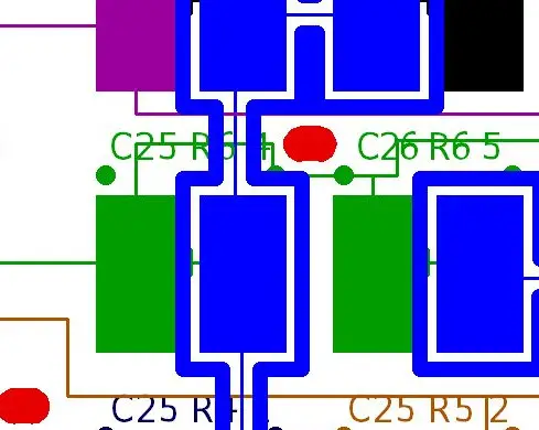
I actually just realized on the following conflict ! Shit !
- answer3.jpg (67.45 KiB) Viewed 5671 times
Knowing myself, I will do it again.
-
idollar
- i$
- Location: Germany (Frankfurt area)
- Main keyboard: IBM F or M
- Favorite switch: BS
- DT Pro Member: -
Another comment to think. Yes, it seems like a sensible thing to do.chzel wrote: ↑If exact placement is an issue, make them a bit oversized, I believe the pressure of the sandwich will keep them in place.
Also, maybe a thinner PCB (0.6mm?) would be better? I worry that 0.8mm will stress the barrel plate too much. We are dealing with potentially brittle plastic, not the metal plate of a Model F.
Thanks !
-
idollar
- i$
- Location: Germany (Frankfurt area)
- Main keyboard: IBM F or M
- Favorite switch: BS
- DT Pro Member: -
I will post tomorrow a new version with the following corrections:
* L-ALT missing connection
* Hole conflicting with the right bottom traces
* Connector / Ground comment
I will print the pcb in paper and check again the position of the holes
I will also think about the 0.6 mm PCB
Thanks for all the comments. I am enjoying the team work.
* L-ALT missing connection
* Hole conflicting with the right bottom traces
* Connector / Ground comment
I will print the pcb in paper and check again the position of the holes
I will also think about the 0.6 mm PCB
Thanks for all the comments. I am enjoying the team work.
-
wcass
- Location: Columbus, OH, USA
- Main keyboard: ibm model m
- Main mouse: kensington expert mouse
- Favorite switch: buckeling spring
- DT Pro Member: 0185
Home printers are not known for their dimensional accuracy. Use the expensive printer at a specialty shop for your final check.
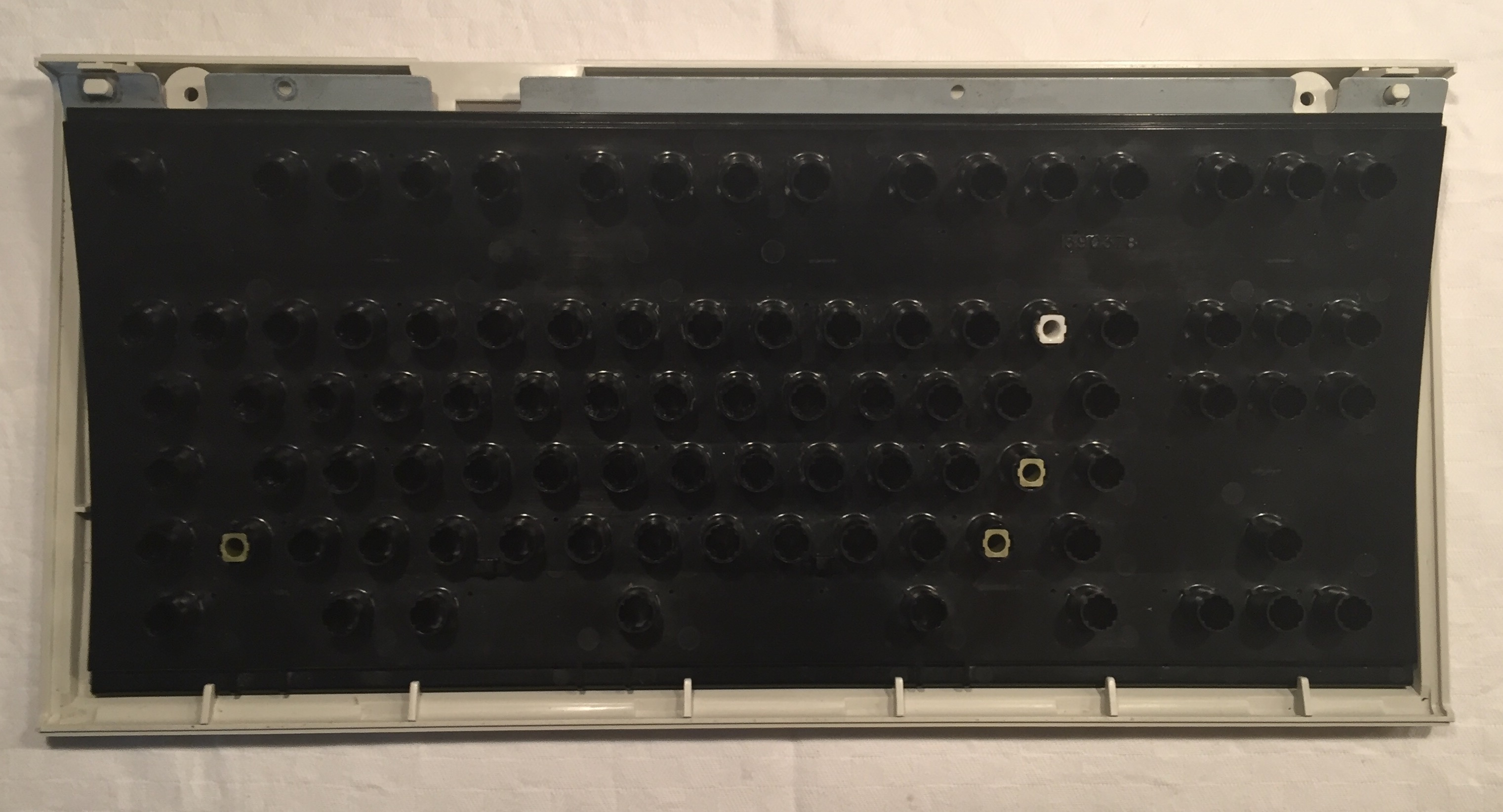
Use the holes on the membranes as a guide on how they should be on the PCB. The hole near the semicolon is uniformly round and small; all of the others are wider. That hole near the semicolon anchors the PCB position left/right/front/back. Other holes on the home row are wider but close to the same height allowing some wiggle room left and right, but not front/back. Off of the home row, holes need to be taller to compensate for mounting the PCB into a curve.
To check hole/pad alignment; use a well worn "top" membrane. You will see that each flipper makes 3 marks; two from the "ears" and one for the "beak". The "ears" need to be on top of the two dots above each key. Try to NOT route any top traces length-wise too near the dots or the "ears" might make it register as a down key.
Consider using the two holes at the top of the back plate (no membrane there) to ground the back plate vs leaving it to "float". The connection for the controller, will there be lumps of wire and solder sandwiched between PCB and back plate? I think i would use FFC and 3 connectors or Z conductive tape - depending on available space.
http://www.digikey.com/product-detail/e ... ND/1002980
http://www.digikey.com/product-detail/e ... ND/4427130
-
idollar
- i$
- Location: Germany (Frankfurt area)
- Main keyboard: IBM F or M
- Favorite switch: BS
- DT Pro Member: -
I plan to use a professional printer with a "painted ruler" along the complete printout, both dimensions, to control the calibration.wcass wrote: ↑Home printers are not known for their dimensional accuracy. Use the expensive printer at a specialty shop for your final check.
I remember the small hole that you have mentioned. I did not think that I could use this as a calibration unit. I will.Use the holes on the membranes as a guide on how they should be on the PCB. The hole near the semicolon is uniformly round and small; all of the others are wider. That hole near the semicolon anchors the PCB position left/right/front/back. Other holes on the home row are wider but close to the same height allowing some wiggle room left and right, but not front/back. Off of the home row, holes need to be taller to compensate for mounting the PCB into a curve.
My membrane is well wornTo check hole/pad alignment; use a well worn "top" membrane. You will see that each flipper makes 3 marks; two from the "ears" and one for the "beak". The "ears" need to be on top of the two dots above each key. Try to NOT route any top traces length-wise too near the dots or the "ears" might make it register as a down key.
The real problem is to avoid routing close to the ears. I have tried but the traces won't fit.
The holes that I have painted are over-dimensioned. I used a conservative approach. I used an Unicomp replacement membrane that I have, which has been checked to be compatible with the original M. The holes in the membrane are much bigger than the originals. The paper check that we will do today may help to reduce them, and perhaps improve the routing over the "ears".
I was also afraid of having two top traces too close. After porting the design to Diptrace, I realised that it can be done.
Also, I am keeping the top traces outside the bottom perimeter between ground lines at the same time that the crossing is still perpendicular. Additional, one has to find the right combination of rows and columns, which makes the design even more interesting
All those contains are difficult to maintain. I do not know how may times I have changed the row/columns allocations. And each time, one have to mirror the top contact and re-draw the bottom layer. A nightmare. In one of these processes I missed the L-ALT contact that you mentioned, probably using the "line square" function. This is why I appreciate so much another set of eyes looking at the PCB.
I planned to cable the ground of the xwhatsit controller to the back plate, as in the original setup. This will link the ground of the PCB to the back plate through the controller.Consider using the two holes at the top of the back plate (no membrane there) to ground the back plate vs leaving it to "float".
I also planned to check with the paper copy if there is an option to ground the PCB directly as you said.
I was already aligned with you
The connector worries me a lot. It must be mounted on top of the back plate. Thus the soldering may be short-circuited with the metal contact with the back plate. There is not option to leave the connection floating. My solution was to use the original membrane under the PCB. On the one hand, it will raise the plate and help with the isolation (isolation tape), on the other it will soft the sandwich contact that otherwise will be just rigid.The connection for the controller, will there be lumps of wire and solder sandwiched between PCB and back plate? I think i would use FFC and 3 connectors or Z conductive tape - depending on available space.
http://www.digikey.com/product-detail/e ... ND/1002980
http://www.digikey.com/product-detail/e ... ND/4427130
We will see the result, again this afternoon with the printout.
Thanks a lot for all your very useful advice/comments. I keep on thanking you in my posts. It is well deserved
-
idollar
- i$
- Location: Germany (Frankfurt area)
- Main keyboard: IBM F or M
- Favorite switch: BS
- DT Pro Member: -
all,
Attached the version of today for checking and, if no errors found, production.
The changes include what was agreed yesterday, holes, and mounting holes in the case (they were missing).
Here the Gerber files:
Here the Diptrace file:
And following the Deltacad file:
EDIT- updated version 0.41 tested holes and quote requeted.
I am eager to read your comments, errors, corrections ... whatever.
----------------
Reminder
----------------
I have created the following spreadsheet to collect the interest and contributions in this project.
Click here
Please write down your interest/preferences.
Attached the version of today for checking and, if no errors found, production.
The changes include what was agreed yesterday, holes, and mounting holes in the case (they were missing).
- FSSK - Diptrace v41 - both.jpg (980.51 KiB) Viewed 5500 times
- FSSK - Diptrace v41 - bottom.jpg (816.4 KiB) Viewed 5500 times
- FSSK - Diptrace v41 - top.jpg (673.24 KiB) Viewed 5500 times
Here the Diptrace file:
And following the Deltacad file:
EDIT- updated version 0.41 tested holes and quote requeted.
I am eager to read your comments, errors, corrections ... whatever.
----------------
Reminder
----------------
I have created the following spreadsheet to collect the interest and contributions in this project.
Click here
Please write down your interest/preferences.
-
idollar
- i$
- Location: Germany (Frankfurt area)
- Main keyboard: IBM F or M
- Favorite switch: BS
- DT Pro Member: -
This is the order that I have put on to get a firm quote.
Lets see ...
Code: Select all
Order Detail

10 units.
Length :	377 mm	Width :	171 mm	Quantity :	10
Layers :	2 layers	Thickness :	0.4 mm	Surface Finish :	Immersion gold
Finished Copper :	1 oz Cu	Solder Mask :	Green	Silkscreen :	White
CreateTime :	1/5/2016 5:14:49 AM	Delivery Type :	3-4 days	Shipping Date :	2016-01-08
Manufacturing :

Total: US $213.00