Custom "75%+1" layout with "Danger Zone" Caps & Dyed Gateron MX Tops

User avatar
richfiles

07 Nov 2016, 12:06

Keyboard75_ParacordBlueYellow.jpg
Keyboard75_ParacordBlueYellow.jpg (484.86 KiB) Viewed 7200 times
So, quick update... Good news and bad news...

The good news, is it sounds like i've gotten in on a plate group buy and will finally be getting the number pad plates made. I should be paying for those soon, I would think. I also found some nice blue paracord with a yellow pattern that I think will work very nicely to sleeve a USB cable! With the number pad looking like it's going to finally be on it's way, I've decided I like Fallout novelty caps, and will probably stick a few on the number pad, treating those keys as additional function keys. I includes a photo of some of the caps I have, temporarily placed in my main keyboard function row, just for the photo.
Keyboard76_OutOfTheVaultMegatonDrop_TestFit.jpg
Keyboard76_OutOfTheVaultMegatonDrop_TestFit.jpg (455.91 KiB) Viewed 7200 times
Keyboard75_1_PlatesDesign.png
Keyboard75_1_PlatesDesign.png (26.44 KiB) Viewed 7200 times
The bad news, is between getting back into construction on my Kerbal Space Program controller, and being busy at work, I've not sat down AT ALL to figure out the programming aspect of this. Seriously... It's been sitting untouched since my last post. I had questions about the firmware, and never got answers, not here, not at DA, not on the TMK tutorial thread... No responses. Being at a roadblock, right when work picked up killed all forward momentum on this project. regaining forward momentum on my other project has left this keyboard sitting.

I really wanna get this finished. I'm SO CLOSE!!! It's just software!

My goals are:

• Figure out the firmware so I can actually use it.
• Figure out how to read a port expander over I2C to read additional keys.
• Figure out how to "skip" the I2C read code when one of the Teensy inputs is low, but perform it when that input is high.

That's what I need to do yet. I can create a simple dummy setup with the port expander to do testing, till my number pad plate arrives. Wiring it will be super straight forward, thanks to the wood pieces already being made. I'll only need to screw the plate on, pop in the switches, install SIP pins and LEDs, and wire the small matrix for the key switches and for the LEDs. One wire of the port expander will go to a transistor driver to run the LEDs, and 12 of the port expander wires will feed the 6 rows and 6 columns of the switch matrix. It'll be a very straight forward build.

I guess there's no point in posting anything further on the software... all my questions remain the same, and are in the last post. I just gotta trudge through it, and maybe see if I can't make it work. I dunno... Software is definitely not my forte... Where designing and building hardware is my hobby and joy, software is like homework, or a job... One I barely am understanding. :?

ArchDill

15 Nov 2016, 05:54

That board is really rad!

User avatar
LeandreN

20 Nov 2016, 02:04

Hey. Just wanted to say that your text posts are really fun to read and the process is cool to follow. Keep it up!

User avatar
TuxKey
LLAP

20 Nov 2016, 17:21

i absolutely love this layout....drool

Finally the two bottom rows are default size.
No crap with a different size spacebar or shift keys..
And all the function keys added on top..

This would make a dream programmable keyboard..i think input club should have a look at this design.
i love both my FC660M mx-clear and FC660C Topre ..But this layout blows everything out of the water.

My compliments to the chef :ugeek:

User avatar
richfiles

21 Nov 2016, 03:53

Thanks for the kind words everyone. I do appreciate it!
I figure once I get the number pad plate in, I'll likely get my second wind.

Also, it'll be winter in Minnesota... I'll have nothing better to do! :mrgreen:

Regarding the layout, I've mentioned it before, but I wanted something that was still space efficient, but also made very few sacrifices in capability and that would still use standard key caps. This particular layout can use any keycap set that works for any standard full-size layout or an 87 key TKL set plus room for one artesian cap.

User avatar
richfiles

20 Dec 2016, 03:16

Keyboard76_NumPadTestFit.jpg
Keyboard76_NumPadTestFit.jpg (288.14 KiB) Viewed 7056 times
So, I gotta drop a big thanks to LeandreN for once again coming through and getting me the plate I needed to finish this project! Number pad plate came in today.

No idea when I'll get it finished, hopefully soon. I counted up my dyed switch tops... I have 30, needed 34. Grr... I gotta mix up a batch of dye for FOUR switch housings! I'm bummed I can't find transparent Plate Mount MX Stabilizers. Sorry, I don't care for Costar, and I don't have a PCB, so the Zeal transparent ones really aren't an option either. For now, I gotta settle with black ones...

Anyway, I have the trim parts already cut out (I did this WAY back when I did the original ones for the main keyboard.
Keyboard76_NumPadTestSSplit.jpg
Keyboard76_NumPadTestSSplit.jpg (335.86 KiB) Viewed 7056 times

User avatar
Plasmodium

20 Dec 2016, 23:42

Really nice to see this coming along! Did you ever get any further with the software?

User avatar
richfiles

21 Dec 2016, 06:50

Honestly... It's been a combination of work, and trying to recover from having spent all day at work. I think the second wind (software wise) will come from seeing absolute completion of the hardware. Then I can sit down and figure it out... I hope! I really don't know C all that well, so i'll be learning as I go.

User avatar
richfiles

22 Dec 2016, 07:54

Keyboard76_FadedDye.jpg
Keyboard76_FadedDye.jpg (153.03 KiB) Viewed 7014 times
It seems my dye might have been a bit... old. It came out more purple than blue. I attribute the color shift to it being LITERALLY a year and 2 months old. Fortunately, I only need four more keys (though I dyed six). I think if key caps are off, it'll stand out, but with key caps on, and if I place them in the center, it probably won't really be noticeable, so I'll give them a pass.
Keyboard76_SwitchesLEDs.jpg
Keyboard76_SwitchesLEDs.jpg (381.68 KiB) Viewed 7014 times
Got the switches dyed, installed, lubed, with SIP sockets inside and LEDs plugged in... That's as far as I've gotten.
The four switches that I just dyed are in the middle. They do look slightly more purple than blue, but it's only slight. I'm more than okay with it.
Keyboard76_NumSwitchAssy1.jpg
Keyboard76_NumSwitchAssy1.jpg (515.42 KiB) Viewed 7014 times
And a pic of the assembly process... I think, if I could go back, I'd have put the numbers on the left, and the extra functions to the right. I just mimicked the typical layout of a full keyboard, but by doing so, I placed my number pad further away from the main keyboard than I needed to. Oh well. Can't change it, so it'll stay as it is. At least Enter will be easy to find by feel.

User avatar
LeandreN

22 Dec 2016, 13:24

This looks fantastic.

Glad you like the plates.

User avatar
richfiles

23 Dec 2016, 06:41

Keyboard76_NP_DZtestFitJoin.jpg
Keyboard76_NP_DZtestFitJoin.jpg (335.57 KiB) Viewed 7019 times
Just threw the number pad keys, and a bunch of various Fallout and mod keys, but yeah, I wanted to see how she looks!
Keyboard76_NP_DZtestFit.jpg
Keyboard76_NP_DZtestFit.jpg (284.74 KiB) Viewed 7019 times
She's a real beaut, isn't she! :mrgreen:
Keyboard76_NP_DZtestFitSplit.jpg
Keyboard76_NP_DZtestFitSplit.jpg (331.79 KiB) Viewed 7019 times
I can't WAIT to have this magnetic split functioning!
Last edited by richfiles on 28 Dec 2016, 01:45, edited 2 times in total.

User avatar
richfiles

28 Dec 2016, 01:41

Keyboard76_NP_DZ_Split.jpg
Keyboard76_NP_DZ_Split.jpg (309.82 KiB) Viewed 6968 times
I worked on this over the Christmas holiday break. You can see the final trim and layout assembly. I might change up the misc keys from time to time, as I get other more interesting key caps. That's why I have a 6x6 number pad! Plenty of room for creative keys! :mrgreen:
Keyboard76_NP_DZ_Join.jpg
Keyboard76_NP_DZ_Join.jpg (419.39 KiB) Viewed 6968 times
The wrist rest is actually just wide enough to type comfortably, and still rest the left side of my right palm on it to reach the number pad, but I plan to make a wide wrist rest and a mini wrist rest in addition to the one I already have. I'll have a spot under my desk to stash the long one and the mini one, so i can bring out the one I want to use. I've also considered just attaching the wrist rests to the keyboard segments. Not really sure on that one yet. We'll see as I use the keyboard and get a feel for things.

I still have to finish some wiring in the number pad, and then do the programming. That's ALL! :D

I'll post more pics soon. ;)

User avatar
richfiles

14 Apr 2017, 09:11

So, I disappeared for a bit... My motherboard died. With only a tablet to rely on, I've not done much here. The good news is, I was able to get my motherboard repaired. The bad... Gigabyte was slow with the whole RMA process. :evil:

I got back on my Kerbal Space Program instrument panel/controller build again, so I've made no progress on the keyboard. It doesn't at all have to do with 4 separate projects vying for space on my work bench, all at once... (Innocently whistles) :roll:

Anyway, I definitely NEED to figure out this whole software thing. I have my first three day weekend in a long time coming up... And I'll undoubtedly waste it, or do hardware instead... That's what I'm craving! LOL :lol:

Maybe I can sit down again and just try... Even if i have to download some "bum code", just to see how it derps up.

Who knows? Maybe it'll actually work?! Beats me... I never did get an answer to any of my software questions. Maybe I need to start a new thread specific to that question. Too tired to do that now... I still have to get up for work one more time before my long weekend.

I feel bad for me, cause I have this lovely keyboard that looks absolutely stunning, but doesn't DO anything, and I feel a little bad cause people thought this project was "days away from completion" a full YEAR ago! Between work and other projects, delays in getting my number pad plate, MORE work delays, injuries (thanks work...), and above all else, my lack of software experience... This is taking painfully long to finish! :shock:
Last edited by richfiles on 07 May 2017, 22:44, edited 1 time in total.

User avatar
shreebles
Finally 60%

14 Apr 2017, 15:28

I say don't beat yourself up over it... it looks amazing and if you get the time and energy to finish one day that's great! It doesn't have to be tomorrow...

I cut a Model M assembly/plate/barrel plate and didn't follow through with cutting the membrane until at least 6 months later... for me it's important for such projects that there is no deadline so you can continue whenever you feel like it. :)

User avatar
Phenix
-p

14 Apr 2017, 17:53

shreebles wrote:I say don't beat yourself up over it... it looks amazing and if you get the time and energy to finish one day that's great! It doesn't have to be tomorrow...

I cut a Model M assembly/plate/barrel plate and didn't follow through with cutting the membrane until at least 6 months later... for me it's important for such projects that there is no deadline so you can continue whenever you feel like it. :)
I tought you dont need the membrane, as you are at your FSSK..

@OP
it is totally fine if you take your time - dont rush, dont pressure yourself.

User avatar
shreebles
Finally 60%

14 Apr 2017, 22:35

Phenix wrote: I tought you dont need the membrane, as you are at your FSSK..
Yeah, I was waiting for a controller that will most likely arrive in the next few days...
So this project sat around for months with no use when I could just have made it another SSK assembly in ISO by cutting the membrane. I had no ISO SSK for a while as I sold two of my three SSKs.

User avatar
richfiles

15 Apr 2017, 19:17

It's noon, and I'm about to go to bed! LOL... Stupid Zelda game on my three day weekend! XD
To be fair, I've spent two full years on my Kerbal Space Program controller, and It's still a good ways away from completion. It's just driving me nuts that my keyboard is effectively done, and nothing more than a dumb question about the firmware has snagged my progress.
Last edited by richfiles on 07 May 2017, 21:50, edited 1 time in total.

User avatar
scottc

15 Apr 2017, 20:53

richfiles wrote: It's noon, and I'm about to go to bed! LOL... Stupid Zelda game on my three day weekend! XD
Oh man... I'm so glad I'm not the only one! I've already wasted all of yesterday and most of today on it and I can't stop...

User avatar
seebart
Offtopicthority Instigator

15 Apr 2017, 22:00

Unbenannt.PNG
Unbenannt.PNG (202.01 KiB) Viewed 6839 times

User avatar
richfiles

07 May 2017, 21:49

Haha! I'm STILL playing that addictive game! Over half a dozen Silver Lynels, 3 Hinox, a Stone Talus, 8 Shrines, and a couple Koroks were laid to waste yesterday! :lol:

Since I couldn't get software specific help for my firmware question a year ago, I'm gonna copy-paste my old question to a new thread... Hopefully a specifically titled thread will have a better chance of an answer, than a question buried in a build thread. I'll copy the answer I get back here once I have an answer. That should go up shortly.

User avatar
Phenix
-p

08 May 2017, 00:14

richfiles wrote:Haha! I'm STILL playing that addictive game! Over half a dozen Silver Lynels, 3 Hinox, a Stone Talus, 8 Shrines, and a couple Koroks were laid to waste yesterday! :lol:

Since I couldn't get software specific help for my firmware question a year ago, I'm gonna copy-paste my old question to a new thread... Hopefully a specifically titled thread will have a better chance of an answer, than a question buried in a build thread. I'll copy the answer I get back here once I have an answer. That should go up shortly.
WHICH Zelda game?
I need something to /waste/ use my time
:lol:

User avatar
richfiles

08 May 2017, 01:33

Phenix wrote:
richfiles wrote:Haha! I'm STILL playing that addictive game! Over half a dozen Silver Lynels, 3 Hinox, a Stone Talus, 8 Shrines, and a couple Koroks were laid to waste yesterday! :lol:
WHICH Zelda game?
I need something to /waste/ use my time
:lol:
The newest one, of course! The Legend of Zelda: Breath of the Wild, on the Switch.
(Also available for the Wii U, if you have ever seen one. LOL) :lol: :roll:

The Switch is pretty great though. I'm blown away by how OFTEN I find myself playing it! Times that I normally wouldn't think I have time to game, I find myself playing. It's beyond convenient to be able to play on the TV, or grab the system and play it as a handheld. It's not at all uncommon for me to play it while the TV is in use... I can't do that on my PS4!

Also went live with my new post, specific to the software questions I have. Initially, I just wanna get the main keyboard firmware programmed. Later, I'll finish wiring the numberpad, and focus on implementing the hot-detachable functionality.

User avatar
richfiles

16 Feb 2018, 16:01

No PCB as of yet, but I DID finally learn how to use KiCAD, so maybe someday in the future. Right now, I'm super busy with my two jobs, and I STILL need to figure out firmware. I was thinking about the following matrix configuration:

Code: Select all

    C0  C1  C2  C3  C4  C5  C6  C7  C8  C9 C10 C11 C12 C13 C14 C15 C16 C17 C18
R0  X   X   X   X   X   X   X   X   X   X   X   X   X
R1  X   X   X   X   X   X   X   X   X   X   X   X   X
R2  X   X   X   X   X   X   X   X   X   X   X   X   X
R3  X   X   X   X   X   X   X   X   X   X   X   X   X
R4  X   X   X   X   X   X   X   X   X   X   X   X   X
R5  X   X   X   X   X   X   X   X   X   X   X   X   X
R6  X   X   X   X   X   X   X   X   X   X   X   X   X
R7                                                      X   X   X   X   X   X
R8                                                      X   X   X   X   X   X
R9                                                      X   X   X   X   X   X
R10                                                     X   X   X   X   X   X
R11                                                     X   X   X   X   X   X
R12                                                     X   X   X   X   X   X
C0-12 and R0-R6 would always scan, looking for whether keys are pressed on the main keyboard.

When the matrix scan reaches R7-R12 and C13-C18, then it would check for the state of the "sense" input to determine if the number pad is present or not. If not present, it would bypass I2C communication and fill in all 36 matrix values with a null value (or whatever represents a button not being pressed). If the "sense" signal detects the presence of the number pad, then I2C commands would be sent to the port expander in the number pad to perform the remainder of the matrix scan.

Since I already have them, I'm gonna switch my LED controls to an I2C DAC (Digital to Analog Converter). It can piggyback on the I2C bus, but it also means I get set and forget LED brightness controls that will be identical on both the main and the numberpad sides of the keyboard interconnect. PWM controls would have been unreasonable on the numberpad side, since it doesn't have a proper dedicated controller. At one point, I'd considered the DAC on the numberpad side, feeding into a 555 timer chip to make a PWM signal, but then I realized I had a dumb moment, and I might as well eliminate flicker and just go with an analog value on both sides. By using identical DACs on both the main and number pad halves, I guarantee the brightness to be the same for all LEDs

Now if only I had enough grasp of any firmwares or of C in general to actually make it happen...
Last edited by richfiles on 23 May 2018, 07:33, edited 2 times in total.

User avatar
scottc

16 Feb 2018, 19:08

That seems like an inefficient matrix - you're using 18+11 = 29 pins which seems like a lot. Do you have a controller with that many pins available? For example, with just 24 pins, you can theoretically do a 12 x 12 matrix and get 144 keys on there. As well as this, there are projects like the ErgoDox, Let's Split etc. that make use of two microcontrollers connected over a TRRS cable; you could do the same here.

Just to start with the main keyboard to begin with: there are threads on DT that explain in a lot of detail how to set up firmware, given a matrix. That would be a good start.

User avatar
purdobol

16 Feb 2018, 20:31

Question time :P
Why use 2 controllers in this case at all? Unless the numpad's supposed to work independently from main keyboard, or there's shortage of pins, then I get it. But if that's not the case, than the easiest way to do this would be:
1. Create matrix with numpad included.
2. Solder the controller on the main board leaving enough pins for the numpad.
3. Solder socket of choice to the "numpad pins".
4. Plug on the numpad and no controller.

Sure it will scan the entire matrix even if numpad is not connected, but I don't see a problem here to be honest.
And it'll be way easier to get the firmware working, if you don't have prior coding experience.

User avatar
bentglasstube

16 Feb 2018, 21:18

The separate controller is because he has them connected via a magsafe connector which has too few wires to direct wire the matrix. Hence there is an i2c pin expander on the numpad side.

User avatar
purdobol

16 Feb 2018, 21:42

Ahh I get it now.

User avatar
richfiles

05 Dec 2019, 07:36

Image

Good Lord, it's been a while! So, I actually sat down and worked on the numberpad LED wiring. This project has literally sat for two years! Originally, I got motivated into working on it, only to find I had made a mistake, and it just deflated any and all motivation. That was coupled with work becoming insanely hectic. Anyway, I'm sticking with my normal routine of splitting the LEDs up into multiple banks. One transistor can't drive all of them (without going to a beefier transistor), but two could. It is honestly just as easy to just split it into three pairs of columns and go that route. One modification that I need to make to this, and the way I'll wire this as well, is that I'll have an I2C Digital to analog converter provide a DC analog output that will drive the LED drive transistors. The thought of trying to do PWM over an I2C port expander sounds like absolute madness. I honestly don't even know if it's possible. I want to make sure the keyboard never draws over 500mA, so it can be easily powered from any USB port, including a common USB 2.0 port. The LEDs are set up so they are in series pairs, drawing about 8mA a pair. Including power dissipation by the resistors, thats about 488mA, with the numberpad attached. I also have to account for the power drawn by the Teensy, the port expander, and the Caps Lock key, which all together, would exceed 500mA.

My solution will be to simply cap the peak brightness when the numberpad is attached. I'd like a 10mA buffer, 30mA to power the teensy, and maybe 10ma for the port expander chip, since all it's doing is scanning the switch matrix. I'll set the I2C DAC inside the Numberpad and inside the main keyboard to the same address, so the teensy can just send out updates periodically, and both will update to matched values. It looks like I can drop current from 8mA to 3mA by just dropping the voltage from 5 volts to 4.5. If I configure the DAC to operate within the range of 4.2-5 volts, that should give me complete brightness control from 1mA to 8mA. Heck, even a mere 8 steps, from 4.2-5 would give me full range, incrementing the output voltage by 0.1 volts per step. 4.9v on the DAC would drop LED current by only 1mA, and allow all 122 keys to be lit at once, with plenty of overhead for the Teensy, etc.

Another thing I've thought about, is a keep alive circuit. Rather than the LEDs flickering out, I think I want a few capacitors in the numberpad, fed through a resistor and diode, to keep power going in case of brief circuit interruption. If I bump the keyboard, and the magsafe connector temporarily separates, having a keep alive circuit will keep the LEDs from flickering, and if the port expender requires any initial setup, it should retain that. The idea is that a resistor limits inrush current, but allows a bank of capacitors to slowly charge up while the keypad is connected. When disconnected, the LEDs and port expander will continue to draw power from he energy stored in the capacitors. It'd probably only be enough for one or two seconds of operation, but it's just a nice consideration to prevent hiccups. The idea came to me from the model train hobby. Locomotives with digital controllers often are fitted with keep alive circuits to allow the locomotive to stay powered when there is dirty track, poor joints, or troublesome track switch points. The capacitors keep the digital controller from resetting, and keep the motor powered for a second or two, so it can power through the area where power is dropping out.

I think I'm finally finding the motivation to get back on this project again!

I may still ask for advice regarding the firmware. I still need to have backlight controls send data to an I2C DAC periodically (on update, on sense pin change, and after time interval), I still need to incorporate the I2C port expander, and above all else, I need to scan a sense pin and have the code skip the Port Expander communications, and return null values, as a conditional based on the state of that sense pin, or possibly a scan timeout.

Soldering circuit boards for work, but once that's done with, I wanna finish the matrix and the rest of the LED wiring, and start looking into how to wire up the port expander, DAC, and transistor drivers.

User avatar
richfiles

10 Dec 2019, 13:08

Image
So with this small modification, I do belive the main keyboard is 100% hardware complete!
I did disconnect the PWM output D7 from the Teensy, freeing up one I/O line. That's not important,
but it did make my previous rework of the matrix from a 7x14 to a 7x13 very unnecessary! :roll:

Image
Image
I have installed a small MCP4725 DAC (Digital to Analog Converter) board into the keyboard to control the LEDs.
It's output was threaded through the existing laced wire bundle, and fed underneath the Teensy.
It's wired to the input of the LED's transistor drivers, connecting where the Teensy's PWM D7 output once connected to.
Power and I2C connections have been made at the tiny board that attaches to the MagSafe port.

Image
I finished the general matrix and LED wiring on the number pad as well! I still need to install the LED transistor drivers,
the port expander, and a second MCP4725 DAC board. There are two options for controlling the LEDs with this setup.
If the DAC boards can receive commands without response, then i can set both boards tot he same address,
and any update sent over I2C should update the output of both boards, changing LED brightness on both keyboard and num pad.
If the chips can't operate in tandem, then I can just change the num pad DAC's I2C address, and send the same data twice, to each address.

One of the nice things about these DACs, is they have an integrated EEPROM that stores the last value,
so it remembers the last brightness setting, even after power off, or number pad detachment.
This means I only have to update LEDs on a brightness change, or after attachment or detachment of the num pad.
The fact that it's a steady analog value also eliminates PWM flicker entirely. The DACs are 12-bits, which is overkill,
but I had them on hand, and they will still work for the application.

After the last hardware is soldered in, it's ALL software from here. I have very little experience there, so advice and help are welcomed.

User avatar
richfiles

22 May 2020, 15:01

The absolute irony of my absolute failure to put in the time to figure out the unique coding situation to resolve the hot-swapability of this keyboard, and the ridiculous amount of time that has passed since procrastinating on finding a solution to the problem, has left me with an unexpected hardware development...
img-3082-2.jpg
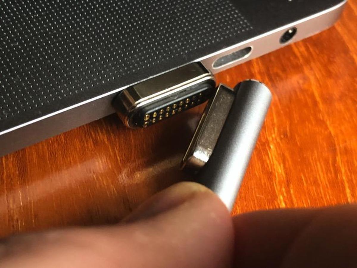
img-3082-2.jpg (111.47 KiB) Viewed 5169 times
In the time that has passed, 20 pin "magsafe style" USB C connectors have been developed, and are now being mass produced. These feature a very dense 20 pin magnetic connector... Honestly... I could essentially "brute force" this entire keyboard, strictly in hardware, if I were to purchase one of these and wire it up to the matrix, LED driver, and power. I might still need the port expander, but it would interestingly enough, end up situated in the main keyboard, and not in the number pad. There would be no risk of hot-swap lockup of the firmware, because the I2C would always remain connected to the port expander. Only the matrix, which is normally open anyway, would ever be disconnected, and the power and LED driver lines are non significant. The power just is or is not connected to the numberpad, and the LED driver output is strictly a passive output. It has no feedback at all. This, while a less elegant a solution, does still suit my style of building well, in that I am, and always have been, a hardware type, not a software type. I may be forced to redo the trim featuring the magnets and magsafe style connector, if I'm unable to pop the old ones out. They were epoxied into place, and may never want to actually come out. I will most definitely be slightly irritated, if I have to redo those parts, as the oak I used was very annoying to work with. We'll see...

If I undo my recent alteration, and Switch the LED control back to PWM on Pin D12, and I eliminate I2C all together, I can reclaim pins D5 and D6, and if I eliminate D24 as a numberpad sense wire, that gives me three unused pins that I can assign as new rows R8, R9, and R10 in the matrix. If I feed Columns C1-C12, and the three new rows, R8-R10, that takes 12+3 pins (15), to do a 3x12 matrix, which would cover the entire 6x6 numberpad (I'd do 2x6 groups of keys as 1 row, and 12 columns, electrically). I'd need two pins for power, plus the LED PWM, adding three more used pins to the total count. That leaves 18 pins used, with 2 unused. If I make the + and - power the same pins as the standard + and - USB connections used on that connector, then even if a USB cable is inadvertently attached to the numberpad, it will actually do nothing (it would actually power the LED driver, but the PWM signal would be off). With no communication, the USB would not negotiate fast charging modes, and thus not increase power above standard USB voltages, so again, the numberpad should be safe. For simplicity, I think the numberpad should mate to a USB cable's mag connector, since it'll be almost entirely passive, and thus have the least risk involved. That, at least, mitigates any risk of damage due to error, for using any manner of standard connector. I do belive I did a similar thing with the old MagSafe connector I used previously, where the main keyboard had the cable connector, and the numberpad had the device connector. As for finding what pins are default USB power (5 volts) on the new style 20-pin magnetic USB-C connector... Well, I'll just have to measure. Finding ground is easy. I just check continuity to the shield. It's also almost certainly gonna be one of the big corner pins... Bigger pins are typically used for power delivery. After I find ground, I just measure the other pins to find 5 volts. Simple!

I think I'm gonna order a few of these from China... They'll probably take a good month to show up. I legit wanted to pick one up for my phone. I do not know yet if I even have room to mount these, nor do I know how much larger they are than the 5 pin connectors (they are definitely larger). I want to search tomorrow to see if I can find the connectors standalone, but I suspect I won't. I'll likely be forced to disassemble a USB-C adapter, extract the connector, and solder some 18 wires to 20 of the pins. Should be fun!

I really should just plan on making a new pair of trim pieces. Like I said, I'll have probably a month to wait for the parts to show up off the slow boat.
1-adet-20-pin-manyetik-USB-C-adapt-r-tipi-C-konnekt-r-PD-100W-h.jpg_q50-2.jpg
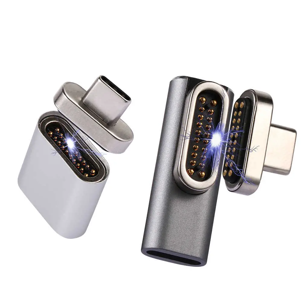
1-adet-20-pin-manyetik-USB-C-adapt-r-tipi-C-konnekt-r-PD-100W-h.jpg_q50-2.jpg (70.98 KiB) Viewed 5169 times

Post Reply

Return to “Keyboards”