Why a tenkeyless Maltron? (Because people who ask why break nothing because they don't get anything done)
Actually, I just type a lot of plain text plus a few programming symbols, so the central key area was generally useless for me. And it meant fewer keys to put diodes in, fewer key modules to buy, fewer keys to buy, fewer things to go wrong, smaller number of controller I/O pins, etc. (And I like the look.)
When I ordered the shells, I had them go ahead and glue in the runners that align the bottom plate because I figured they'd have a better chance of getting them to align right than I would. Some thinks it impedes access to the function row, but that area is tight no matter what. I also had them leave the USB and LED holes un-punched.

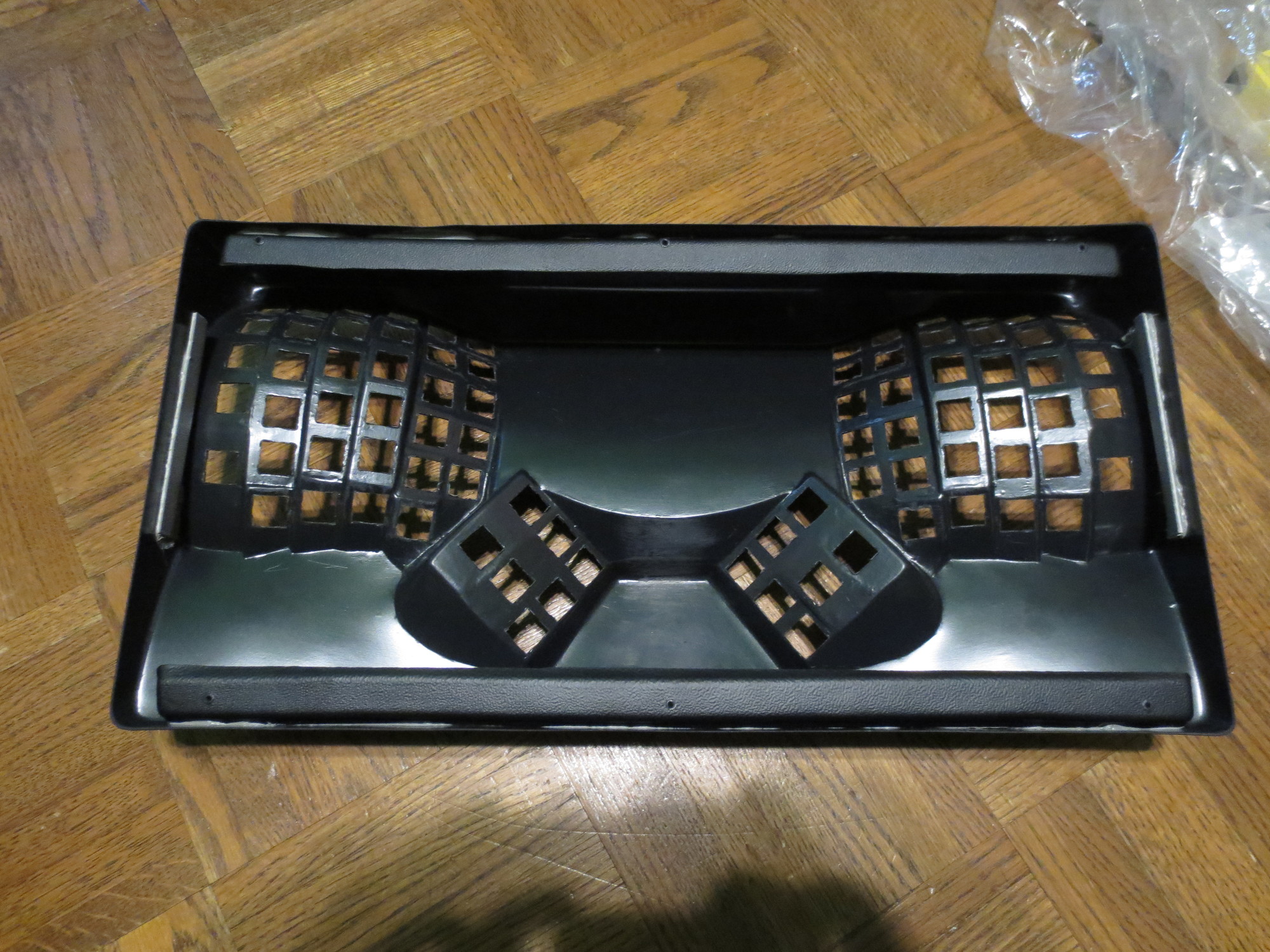
- view of case from top
- IMG_1649.JPG (702.7 KiB) Viewed 4920 times
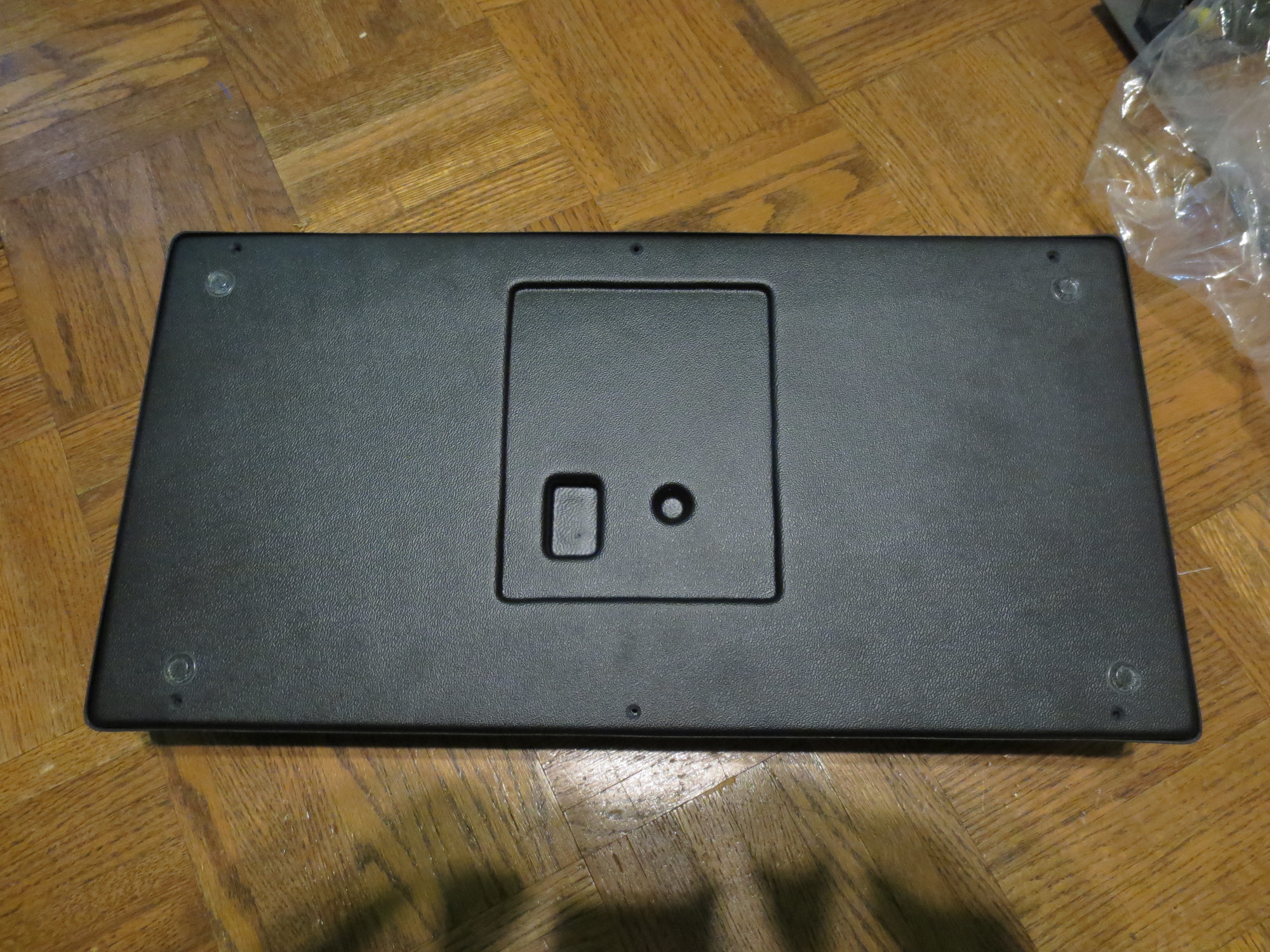
- view of case from bottom
- IMG_1650.JPG (873.23 KiB) Viewed 4920 times
- view of bottom plate
- IMG_1648.JPG (690.8 KiB) Viewed 4920 times
I z-bent a length of .5" aluminum bar, drilled it to attach the PCB, and sanded + gouged the inside of the case to get a good adhesion and attached it with JB Kwik / Kwikweld.
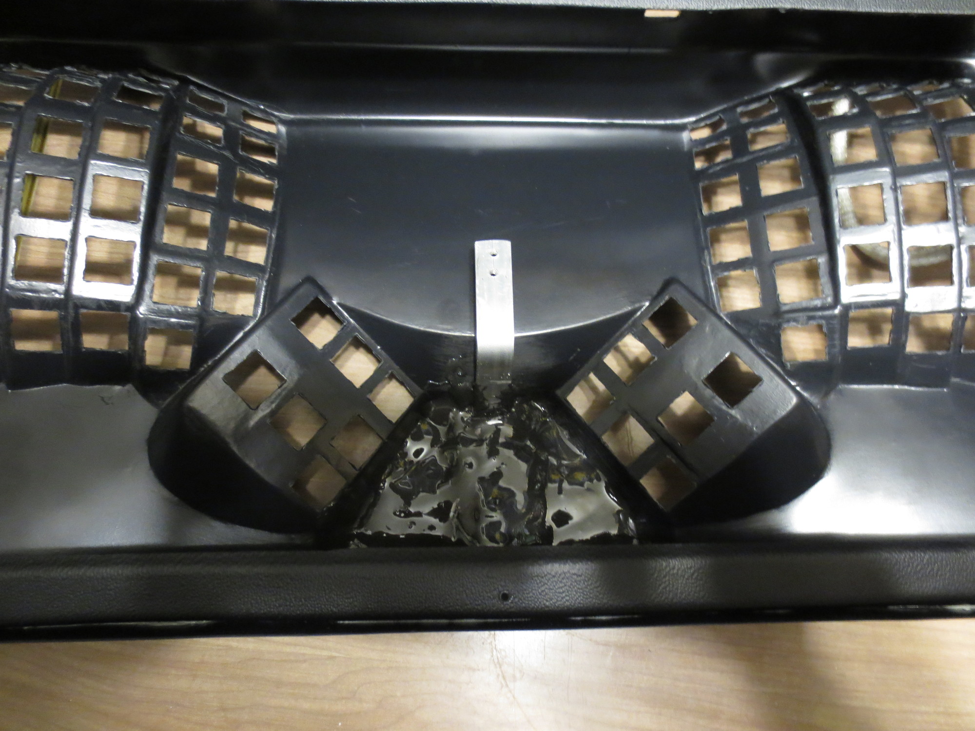
- JB weld
- IMG_1658.JPG (519.92 KiB) Viewed 4920 times
Then, after measuring against the PCB, I cut and drilled the USB hole.
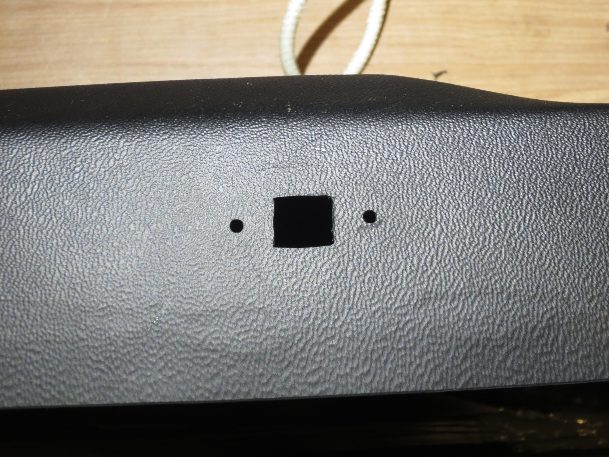
- USB hole
- IMG_1661.JPG (795.17 KiB) Viewed 4920 times
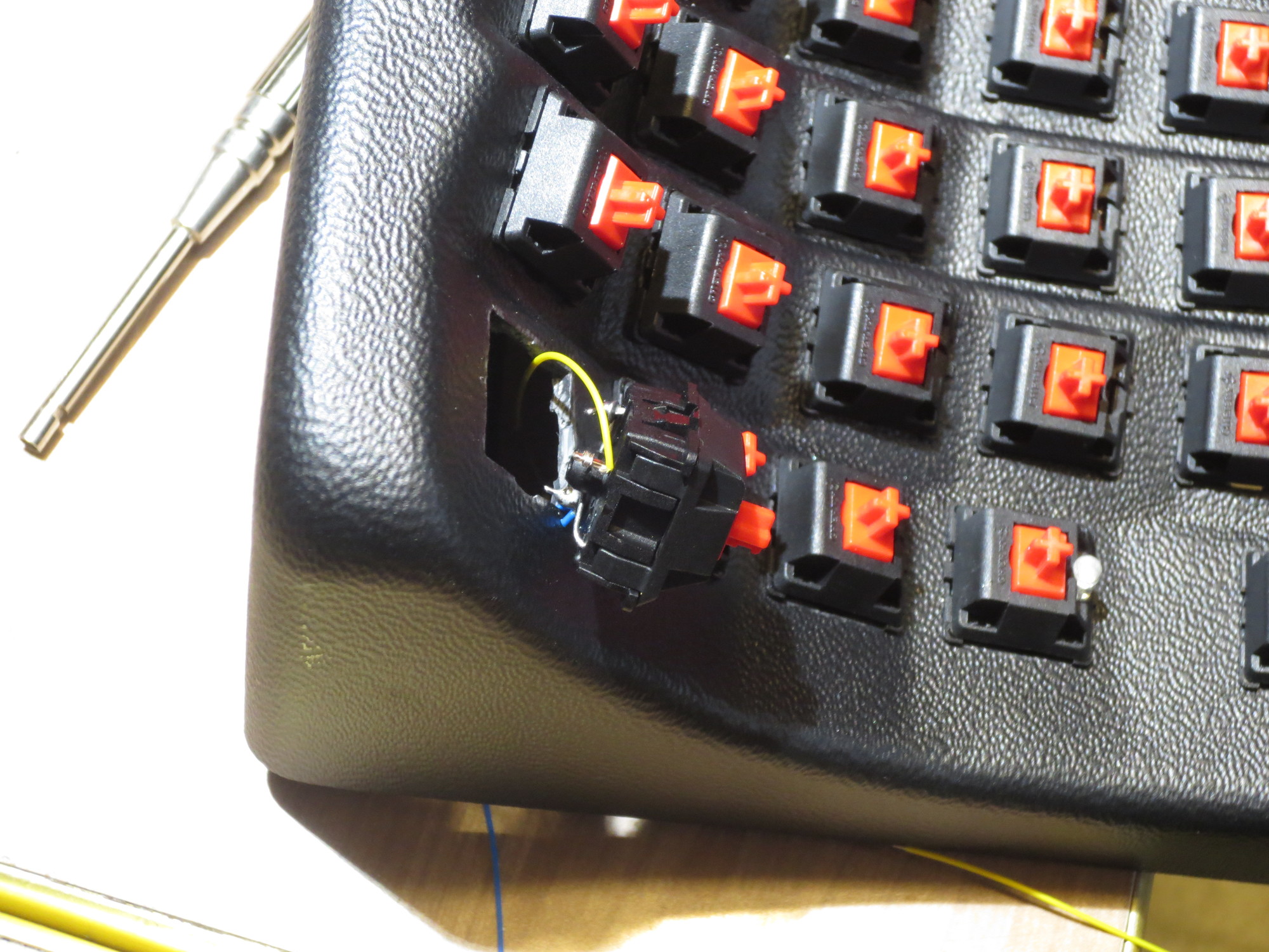
(using Cherry MX reds, obviously) I cracked open 82 switches and install diodes. For parts of the installation I was using a wire-wrap tool to give the wire a tight connection to the post, but one pin on the cherry module is too thin to withstand the twist, so I routed the diode to that pin and soldered it and used the stronger pin to attached the column wires.
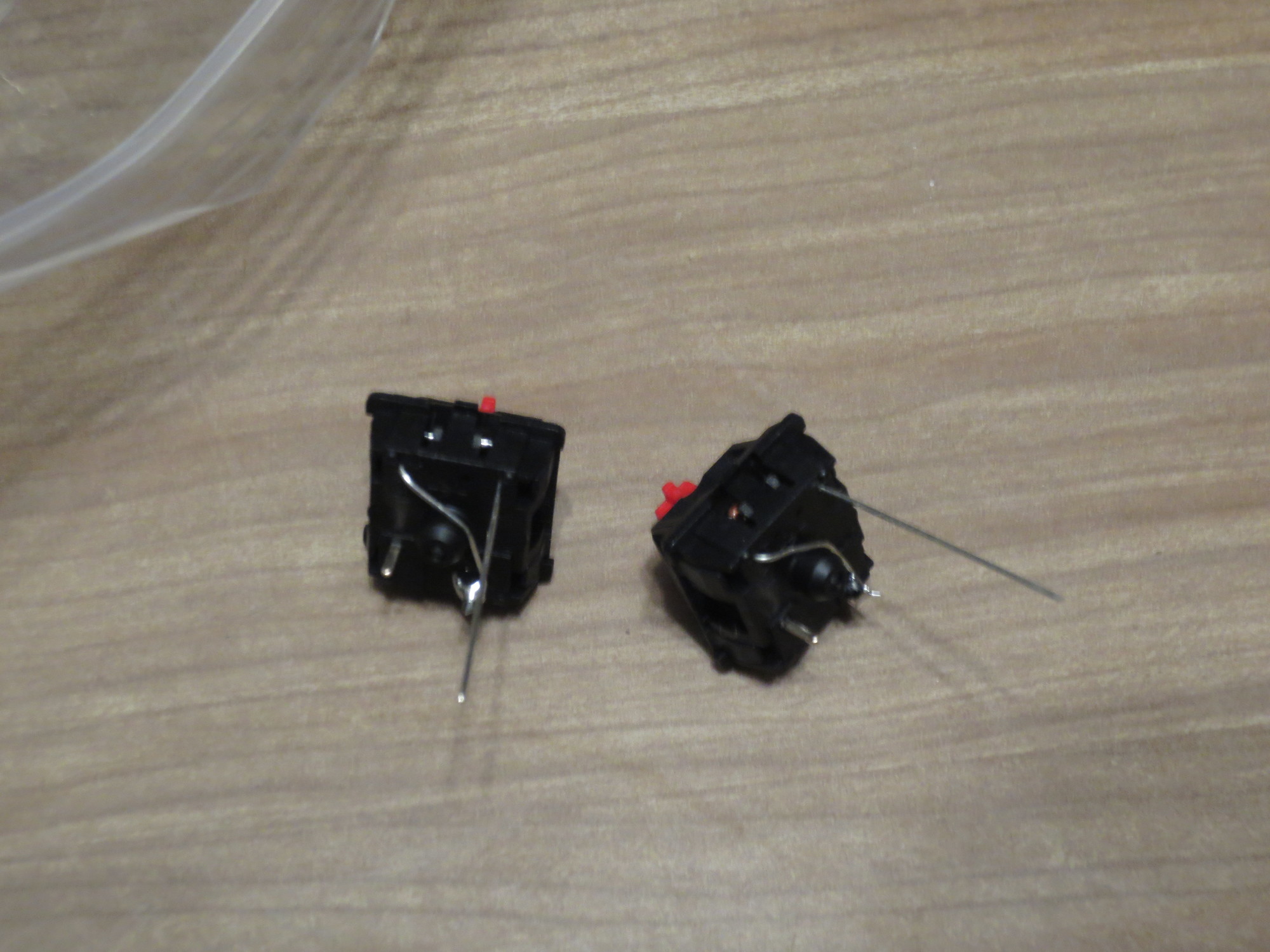
- modules + diodes
- IMG_1659.JPG (409.5 KiB) Viewed 4920 times
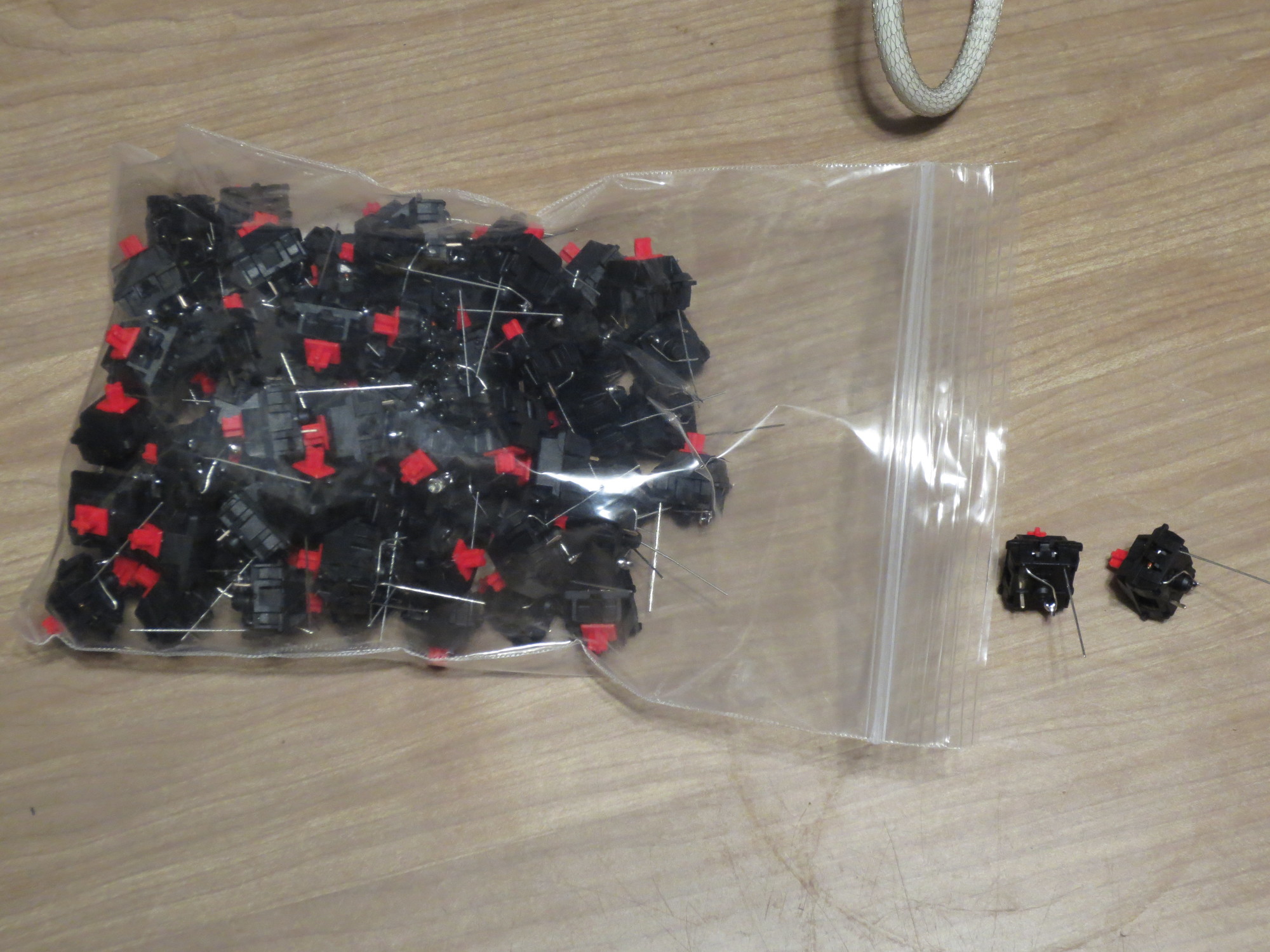
- bag of dioded modules
- IMG_1660.JPG (522.91 KiB) Viewed 4920 times
I started with the function row, and instead of working from the back, threaded the wire through the holes, soldered it and placed the switch. At the end I realized i should've done this row last, because I had to pop them back out to attach and feed through the column wires. For the first couple of switches I burned the insulation off with the soldering iron, but didn't like the results. So I started feeding lengths through an OK machines ST 100 stripper (straight down through the blades at intervals) and pulled the wire out and broke the rest of the insulation with my nails and pulled a gap in it. The insulation on this 28AWG wire-wrap wire worked nicely that way.
- stripped wire
- IMG_1677.JPG (962.65 KiB) Viewed 4920 times

- sewing
- IMG_1663.JPG (800.27 KiB) Viewed 4920 times
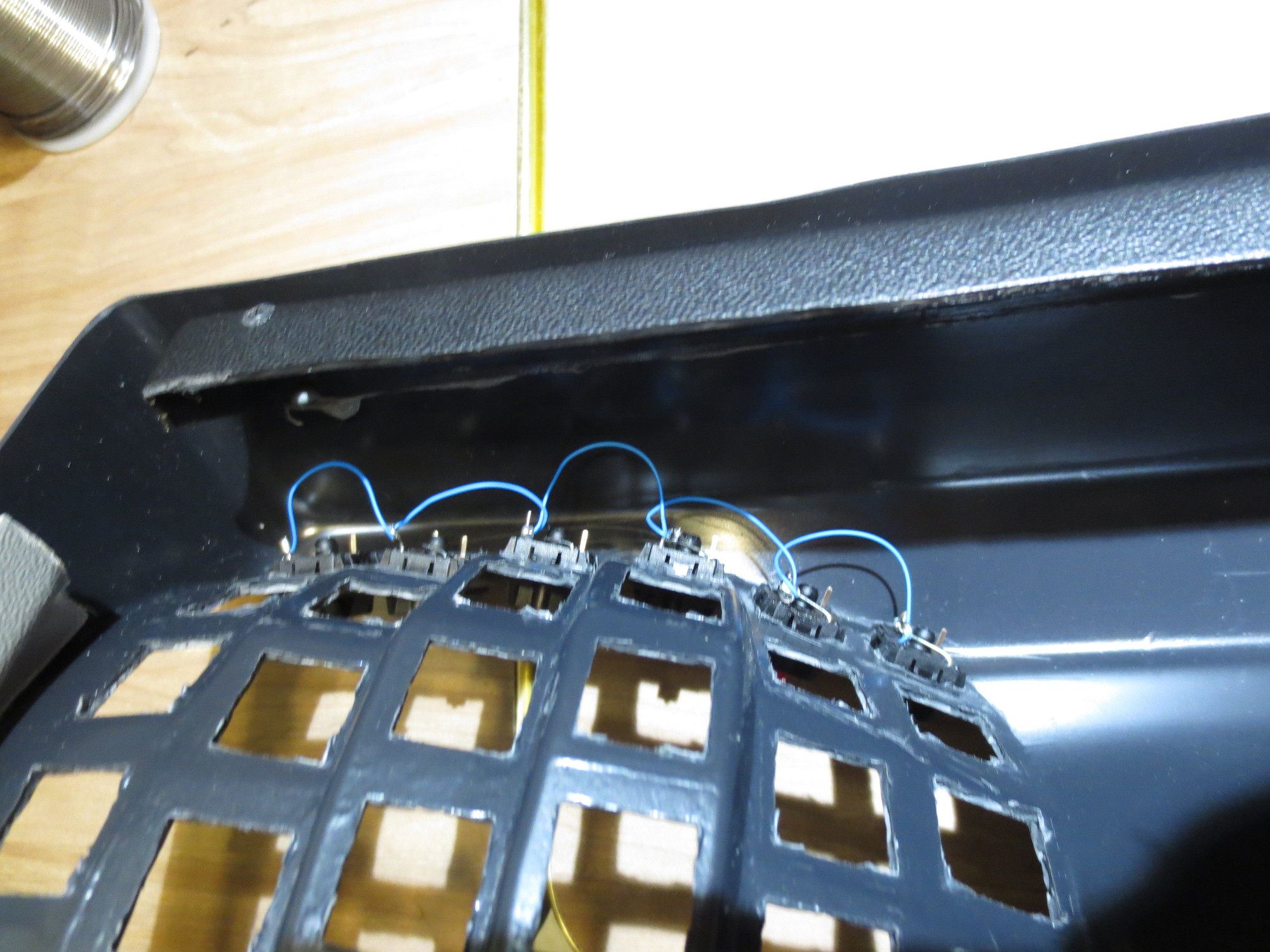
- f-row backside
- IMG_1666.JPG (465.48 KiB) Viewed 4920 times
- popped module
- IMG_1675.JPG (591.51 KiB) Viewed 4920 times
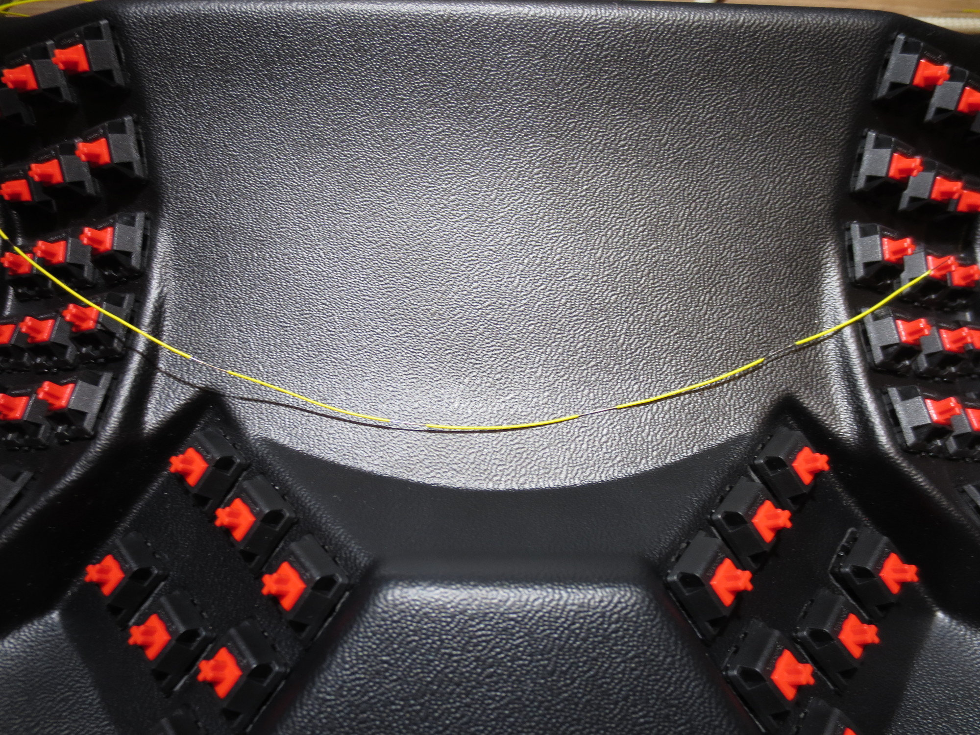
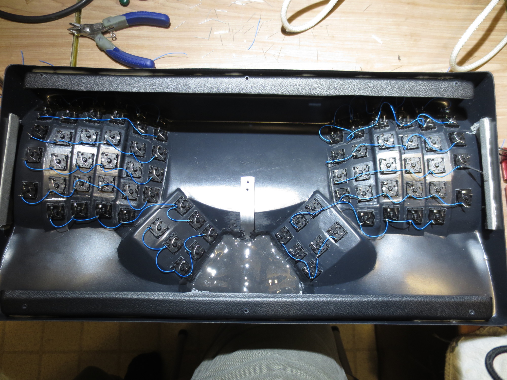
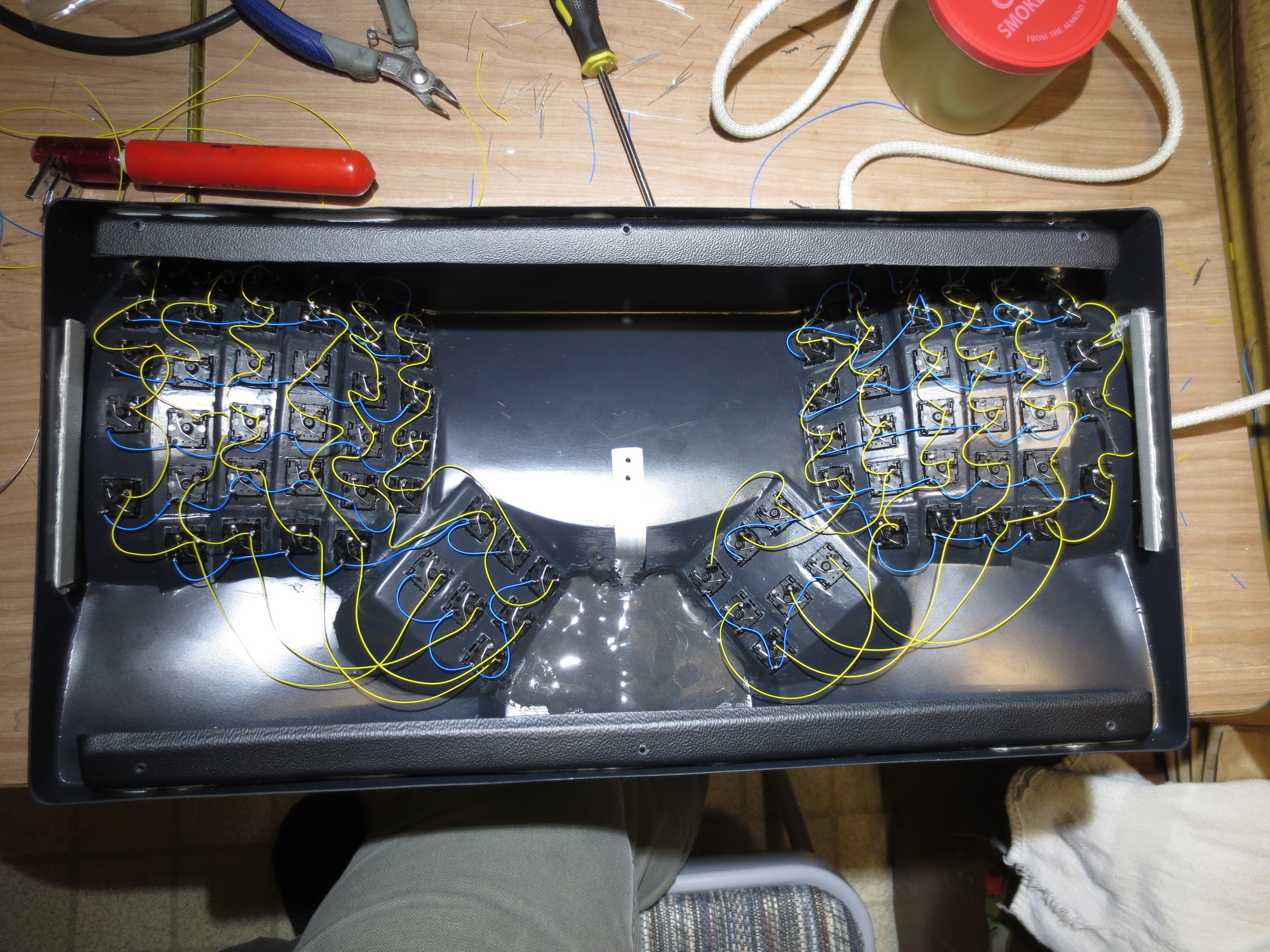
Then it's just a matter of working through all the column and rows.
- rows
- IMG_1669.JPG (754.26 KiB) Viewed 4920 times
- cols
- IMG_1678.JPG (847.11 KiB) Viewed 4920 times
Then wiring up a cross-connect to the rows on each side, and attacking ribbon cables and connectors for the columns, rows, and a capslock LED. Instead of drilling a hole, I fitted the LED in the switch. To get both the LED and diode in, I put heat-shrink tubing on the LED's leads, which meant I had to re-drill the hole in the module.
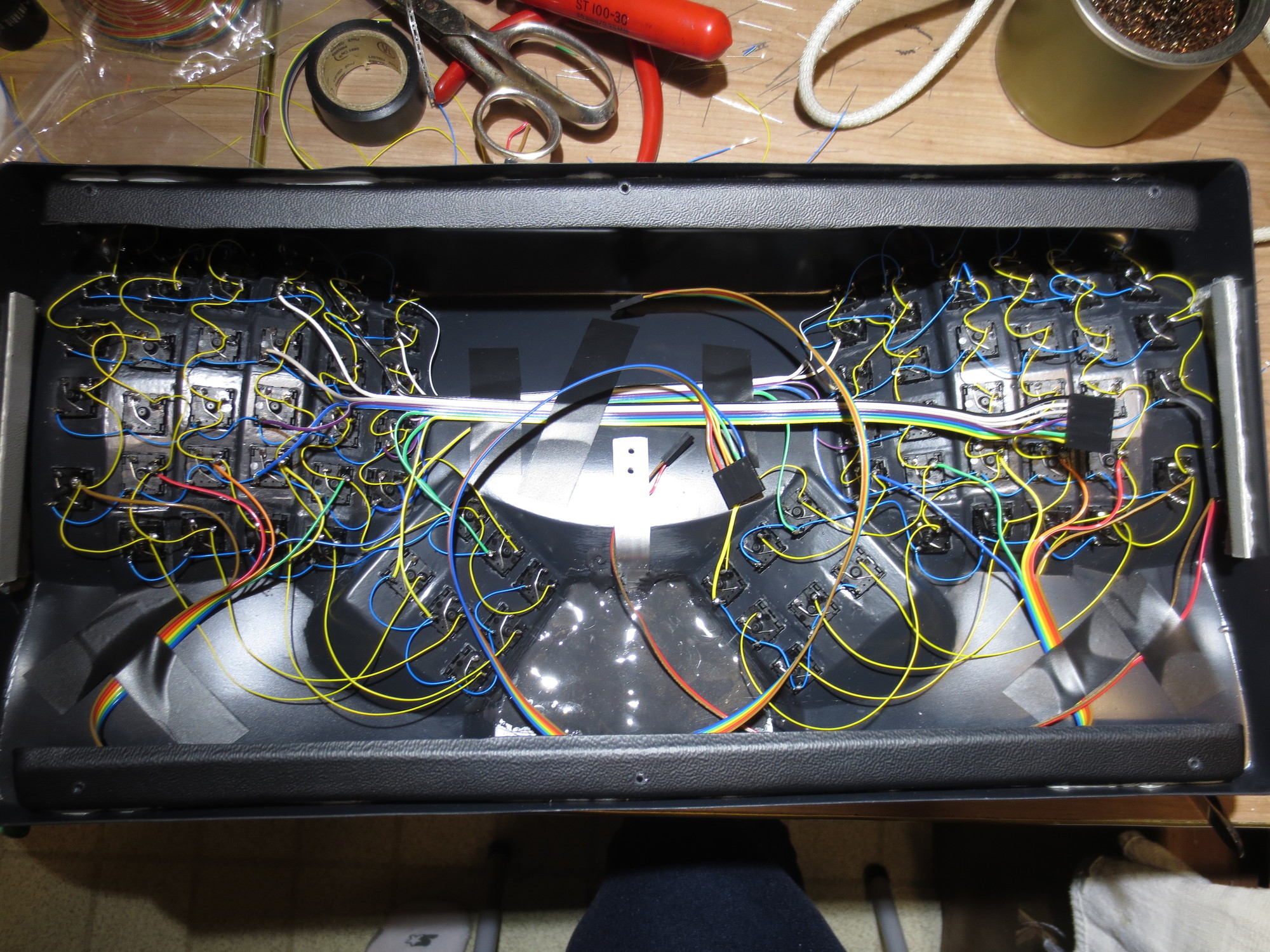
- cabling
- IMG_1684.JPG (816.9 KiB) Viewed 4920 times
TO BE CONTINUED...

