Flashing bootloaders on AVR
This page contains some general information about flashing AVR chips, with keyboard enthusiasts in mind. It is meant to help with "bricked" keyboards, i.e. when the keyboard won't even enter the bootloader mode. If you can put your "bricked" keyboard into the bootloader mode somehow, then you should follow a firmware flashing guide for your particular keyboard.
The guide is quite general, and it is only meant to explain the basics (so that you can google more specifically). The particulars depend on your PCB/chip, available AVR ISP programmer and PC.
Contents
Flashing ATMEL chips on keyboards with a programmer: A general guide
So, you've somehow bricked the ATMEL chip on your keyboard and the bootloader doesn't work anymore. You want to reflash the bootloader.
Mind you, this (completely bricking a keyboard) is kind of hard to do, but I guess it happens.
Now, the task is to (try to) reflash the bootloader to the chip. (This also applies if you want to change the bootloader to another, e.g. GON's to DFU.)
To start with some background, ATMEL chips are traditionally programmed with an AVR ISP Programmer, a device which can talk to the AVR chip even if it's empty or has a non-working garbage for a firmware. (Bootloaders are just a special pieces of firmware sitting in the AVR chip's flash, so they can get corrupted, even though there are quite some guards within the chip against that.)
So the general diagram is:
PC {--1--} AVR ISP Programmer {--2--} AVR chip (e.g. in a keyboard)
Now I'll give some comments about various pieces in the above diagram.
PC
Whatever PC would work, but the situation is (as usual) much simpler on Linux or macOS than on Windows.
The end goal is to have a piece of software that can talk to the ISP Programmer, and drivers that allow it talk to the Programmer (this is only an issue on Windows; Lin/X work out-of-the-box). The usual one to use is avrdude. On linuxes, it is usually available through your package manager; on macOS it is installable through homebrew {and brew tap jpommerening/avr}. On Windowses, either google for an avrdude.exe, or get the Arduino GUI, avrdude comes with it (a big download for a 200kB binary).
Now drivers on Windows - that will depend on the Programmer that you'll use. In what I'll be writing about, we'll use an Arduino, which will appear as a serial port on your PC, so you'll need an .inf file for that. It comes with the Arduino GUI, and you can follow the instructions there.
AVR ISP Programmer
That's the device that will sit between your ATMEL chip and PC. There's really a plethora of options; but for a one-time rescue effort an Arduino is an option. Dedicated Programmers generally come already "working", i.e. you would just plug them into PC, connect to your ATMEL chip, and use avrdude to program the ATMEL chip.
However if we'll be using an Arduino, we need to program the Arduino so that it will behave like a Programmer. The easiest way to achieve that is to run the Arduino GUI, select "File > Examples > ArduinoISP", compile and program the sketch into your Arduino. That's all good, but there may be a couple of snags that you encounter when you try using it; most notably you'll need a 10uF capacitor between RESET and GND on Uno (see here); and you'll need to edit the sketch a bit for a Leonardo or a Teensy; and finally the pins on the arduino where your ATMEL chip should be are different than Uno's (for these two see here). Using Teensy is most painless, you can use the diagrams here to figure out which pins to use.
About {--2--}
How to connect the programmer to your ATMEL chip? You'll need 6 wires. One for GND, one for VCC (to power up the ATMEL chip) and 4 for communication. Three of those are the "SPI" pins, called usually MISO, MOSI, SCK. These will be connected accordingly, i.e. MOSI on your programmer will go to MOSI on the target chip, etc. The last connection is some pin (usually SS or CS or Chip Select, but this can vary) on the programmer should be connected to RESET on the target chip.
Now you'll need to figure out which pins are these on both of your devices. Here are some links.
Programmers pins
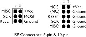
- if you have a proper programmer, it will most likely have either 2x3 or 2x5 connector like this.
- for Arduino Uno, use this - it's pins 10-13.
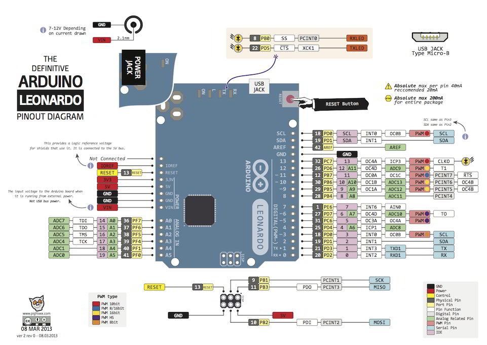
- for Arduino Leonardo, use this - note that the SPI pins are on the 2x3 connector, not on the main headers.
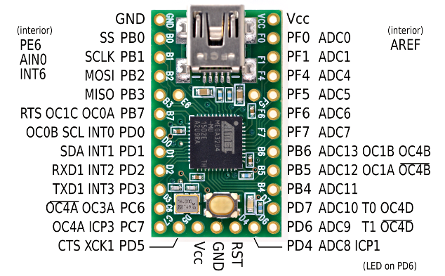
- for Teensy, use this.
Target ATMEL chip pins
This will really depend on your chip/keyboard. If the keyboard designer was reasonably nice, you can find the (by now hopefully) familiar 2x3 ISP header somewhere on your PCB. If it's not there, you might end up soldering wires to MCU pins...
Anyway, to check that the connections are correct, you should read you MCU type on the chip (usually atmega32u4, atmega32a or atmega32u2), google "{your-mcu-type} pinout" images, locate the SPI and RESET pins and check that they're connected where you think they're connected on the PCB.
Okay, we've got all connected, what now?
Well, now you can use avrdude to program the target chip. How, you ask?
I guess before moving on, here's a BEWARE: by programming the chip via avrdude and a programmer, you'll most likely erase the bootloader. avrdude performs the whole flash erase operation by default (this includes the bootloader!) before doing any writes. This is possible to disable using -D option, but ... just be warned.
The usual course of action would be to use avrdude to program the bootloader (and the fuses if they're wrong), and then program the actual firmware the usual way, using the freshly burned bootloader. (Note "fuses" in the AVR lingo just mean a couple of special "configuration" bytes that affect the chip's behaviour; they can be only changed using a programmer.)
So, as a first step, just see if the programmer can talk to the chip:
avrdude -c {programmer} -P {serial-port} -p {chip-name}
Where {programmer} is your programmer's nickname (get a list of the possibilities with avrdude -c help; ArduinoISP is arduino) and {chip-name} is the chip's nickname (again, get a list with avrdude -c arduino -p help; atmega32u and atmega32a are the common ones). Finally, for the programmers that use serial port (e.g. arduinoISP), {serial-port} is that (usually comX on windows and /dev/ttySTUFF on normal systems).
You also may need to add -b {baud-rate}, just try 19200, 38400, 57600, 115200 for the baud rates, one of them should work.
If there's a problem, you'll definitely notice from the output. If it goes well, it should say Device signature ... and Fuses OK. An error usually means that the communication isn't happening properly.
Now the syntax to read and write the target chip's flash is quite weird. So, as a start, to read the whole flash, use the above avrdude command and append -U flash:r:firmware.hex:i to get a hex file, or -U flash:r:firmware.bin:r to get a binary file (this one is easier to inspect than the hex if needed).
What bootloader to write?
There's usually quite a few bootloaders that you could use; but this would be for another document. So just briefly - atmega32u4-based keyboards generally seem to use the DFU bootloader, and that one's possible compile yourself either from ATMEL's sources, or from the LUFA library.
For the atmega32a-based keyboards, you should first try to get the one that your PCB came with - and this generally means asking the person who made it for one. They are all based on the same code bootloadHID, but the point is that keyboard makers seems to do some modifications to it, namely the condition when to enter the bootloader, and maybe add some visual signal that the bootloader is running.
(To fill in some general info on AVR bootloaders, here's how things work: The upper part of the flash memory on AVR chips ("the end") can contain some bootloader code. When an ATMEL chip powers up or resets, it checks its fuses, and if they say that it should start with a bootloader (rather than normal firmware at the beginning of the flash), it starts executing the code near the end of the flash memory - where the bootloader should reside. Now the bootloader somehow determines whether it should jump back to the "application code" at the beginning of the flash, or whether it should continue running.)
About the fuses
These should really not require any modifications. Note that it's possible to almost "brick" the chip by setting "wrong" fuses (yeah, it's almost always possible to recover, but it may require more equipment and maybe soldering).
If you are curious about them, the AVR8 chips usually have 3 fuses (called "low", "high" and "extended"), each of them is a byte. You can find out by running avrdude (with the correct -p and -c); it should say Fuses OK (E:{byte} H:{byte} L:{byte}). These bytes are fuses.
Here is a great database of what various bits in the fuse bytes actually stand for. Google.